
K-WANG
+086-15305925923
Service expert in industrial control field!


Product
Article
NameDescriptionContent
Adequate Inventory, Timely Service
pursuit of excellence


Ship control system
Equipment control system
Power monitoring system
Brand
Product parameters
- Telephone:+86-15305925923
- contacts:Mr.Wang
- Email:wang@kongjiangauto.com
Description
The Relay Output Module provides eight individual
galvanically isolated, electromechanical relay outputs.
Four of the outputs are Form-C, and the other four are
Form-A. Outputs are not fused in the Relay module.
Install a fuse for each output at the field device that is
appropriate for the load and the wire used.
Honeywell Analog Input Hi level (16ch)900A16-0101
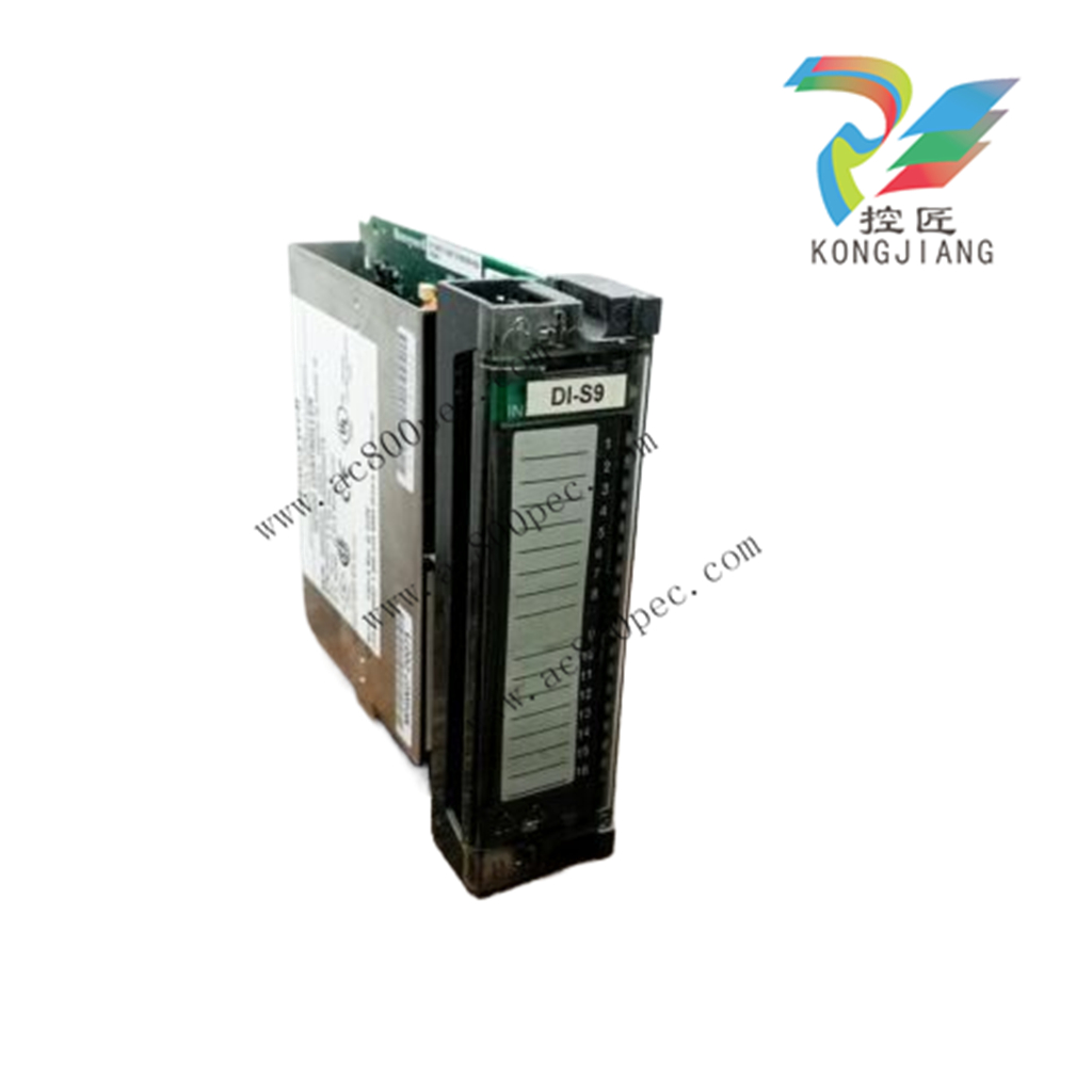
Relay Output Module (900H01-xxxx)
The Relay Output Module provides eight individual
galvanically isolated, electromechanical relay outputs.
Four of the outputs are Form-C, and the other four are
Form-A. Outputs are not fused in the Relay module.
Install a fuse for each output at the field device that is
appropriate for the load and the wire used.
There is a green LED state indicator for each channel on
the module to indicate when a digital output is ON.
A green blinking status LED on the module indicates
when the module is being scanned. An amber blinking
status LED indicates when channels are forced and a red
status LED when module diagnostics exist.
8 Relays per module 4 form A, 4 form C
Output Device Electromechanical relay
Voltage 120/240 VAC, 30 VDC
Current Rating 4A @ 240VAC or 30VDC resistive load
0.5 A @ 240VAC or 30VDC incandescent lamp load
Galvanic Isolation Relay Output Contact to Relay Output Contact
Relay Output Contact to Logic
Max. Leakage Current 1 mA @ 350 VDC
De-rating Max. outputs at max. load – none
Max. modules per rack - none
OFF to ON response time* 11 ms max
ON to OFF response time* 8 ms max
Power Supply Loading 5V; 110mA max
24V; 100mA max
Expected life (min.
operations)
Mechanical at 180 cpm: 5 x 10E7
Electrical: 10E5
*excluding controllers scan time and excluding transmission time from module to backplane
Life expectancy curves (1a1b type)
Digital Output Module – DC Type (900H02-xxxx)
The DC Digital Output module provides 16 outputs
separated in to 2 groups of 8 channels each that are
powered externally. Each group has a pair of screw
terminals for +V and COM connections. The outputs are
low side switching (current sinking) type. Overload
protection is built into each output; when tripped the
power must be recycled to reset the module.
There is a green LED state indicator for each channel on
the module to indicate when a digital output is ON.
A green blinking status LED on the module indicates
when the module is being scanned. An amber blinking
status LED indicates when channels are forced and a red
status LED when module diagnostics exist..
Outputs per module 16 (current sinking, low side)
Galvanic Isolation 2 groups of 8 outputs
Operating Voltage 6.5 to 32 VDC (5.0 to 6.5 V @
<0.5A per channel)
Output Type Intelligent power switch (IPS)
Peak Voltage 34 VDC
AC Frequency N/A
ON Voltage Drop 0.3VDC @ I A load
Overload Protection Electronic high current and high
temperature limiting, resets after
cycling field power
Maximum Load
Current
1 A per point, 8A max. per
module, resistive load
0.5 A per point incandescent
lamp load (5 mH max)
Maximum Leakage
Current
0.15mA @ 32 VDC
Maximum Inrush
Current
4 A for 10 ms
Minimum Load 0.0 mA
OFF to ON response
time*
6 ms
ON to OFF response
time*
6 ms
Fuses Electronic limiting
Power Supply
Loading
5V; 340mA
24V; 0mA
*excluding controllers scan time and excluding transmission time from module to backplane
Purchase history
| User name | Member Level | Quantity | Specification | Purchase Date |
|---|
Total 0 Record
Related products
Customer Reviews
Satisfaction :
5 Stars
No evaluation information


- other
- LTI Drives
- ADLINK
- Beckhoff
- Other Brands
- AMAT
- Iba
- PEPPERL+FUCHS
- Aerotech
- WATLOW
- MAN
- ADVANCED
- Abaco
- YOKOGAWA
- KOLLMORGEN
- MEGGITT
- kong-sberg
- METSO
- Motorola
- NI
- OEMAX
- RELIANCE
- scanlab
- schneider
- uniop
- Vibro-Meter
- Honeywell
- Rolls-Royce
- MOOG
- GE
- B&R
- Woodward
- Yaskawa
- xYCOM
- Siemens
- Emerson
- HIMA
- Bently
- ZYGO
- FOXBORO
- OMACO
- PROSOFT
- ENTERASYS
- TRICONEX
- Parker
- Lenze
- KEBA
- Alstom
- CTI
- ABB
- A-B
142

-
 ADLINK PCI-9112/cPCI-9112 multifunctional acquisition card
 -
 ADLINK PCI-8102 Two Axis Pulse Motion Control Card
 -
 ADLINK PCI-9812/PCI-9810 synchronous 4-channel high-speed acquisition card
 -
 ADLINK PCI-7200/cPCI-7200 high-speed digital I/O board
 -
 ADLINK MXE-1000 series fanless embedded machine
 -
 ADLINK IMB-T10 Mini ITX Industrial Motherboard
 -
 ADLINK HSL Distributed High Speed I/O System
 -
 ADLINK PXI/DAQ/DAQe-2500 series multifunctional analog output DAQ card
 -
 ADLINK PXI/DAQ/DAQe-2200 series multifunctional data acquisition card
 -
 ADLINK ETX-AT ETX Core Computer Module
 -
 ADLINK ACL-7225 ISA 16 channel relay output+16 channel isolated digital input card
 -
 ADLINK DAQ-2000 series synchronous acquisition card
 -
 ADLINK NuPRO-E330 PICMG 1.3 full-length industrial motherboard (SHB)
 -
 ADLINK ACL-8112 series multifunctional ISA acquisition card
 -
 ADLINK USB-2405 24 bit dynamic signal acquisition module
 -
 ADLINK PXIS-3320 15 slot 6U PXI chassis
 -
 ADLINK PCIe GIE7x series acquisition card
 -
 ADLINK PCIe-7856/PCIe-7853 Distributed Motion and IO Main Controller PCIe Acquisition Card
 -
 ADLINK PCI-6308 series isolated analog output board
 -
 ADLINK PCI-7432 Isolated Digital I/O Acquisition Card
 -
 ADLINK NuPRO-E72 PICMG 1.3 Full length Industrial SHB Single Board Computer
 -
 ADLINK MXE-5400 series fanless embedded industrial computer
 -
 ADLINK M-322 Industrial ATX Motherboard
 -
 ADLINK IMB-M43H Industrial ATX Motherboard
 -
 ADLINK IMB-M42H Industrial ATX Motherboard
 -
 ADLINK i915GV-INA ATX motherboard
 -
 ADLINK ETX-NR667 Embedded ETX Standard Computer Module
 -
 ADLINK ETX-BT (PATA to SATA version) User Manual
 -
 ADLINK CM1-BT1 PC/104 Single Board Computer
 -
![ADLINK cPCI-8217 [R] 3U CompactPCI VGA/LCD Display Module](https://aosspic10001.websiteonline.cn/hkw632bc8/image/image_aJXQRn.png) ADLINK cPCI-8217 [R] 3U CompactPCI VGA/LCD Display Module
ADLINK cPCI-8217 [R] 3U CompactPCI VGA/LCD Display Module -
 ADLINK AmITX-SL-G Mini ITX Embedded Motherboard
 -
 ADLINK AmITX-AL-I ultra-thin Mini ITX industrial motherboard
 -
 ADLINK NuPRO-E315 Full length PICMG 1.3 Industrial SHB Single Board Computer
 -
 ADLINK NuPRO-842 Full length PICMG 1.0 PCI/ISA Industrial Single Board Computer
 -
 ADLINK NuPRO-900A PICMG 1.2 ePCI-X Dual Xeon Industrial System Motherboard (SHB)
 -
 ADLINK cPCI-6910 series 6U CompactPCI single board computer
 -
 ADLINK cPCI-6860A 6U CompactPCI dual core single board computer with cPCI-R6860A rear adapter board
 -
 ADLINK cPCI-8168 6U CompactPCI Eight Axis Motion Control Card
 -
 ADLINK NuPRO-E340 PICMG 1.3 Industrial SHB motherboard
 -
 ADLINK NuPRO-A40H Full length PICMG1.0 Industrial Single Board Computer (SBC)
 -
 ADLINK NuPRO-852 Full length PICMG1.0 Industrial Single Board Computer
 -
 ADLINK NuPRO-841 Full length Industrial SBC
 -
 ADLINK NuPRO-590/591/592 series Socket7 full-length industrial SBC
 -
 ADLINK MXE-5500 series fanless embedded industrial computer
 -
 ADLINK MXE-200/200i Fanless Embedded Machine
 -
 ADLINK cPCI-6770 series CompactPCI CPU board
 -
 ADLINK NuPRO-A301 standard PICMG 1.0 full-length industrial SBC single board computer
 -
 ADLINK NuPRO-965 PICMG 1.3 SHB Express Full length Industrial Motherboard
 -
 ADLINK NuPRO-935A Full length PICMG1.0 Industrial Single Board Computer
 -
 ADLINK NuPRO-865 Full length Single Board Computer
 -
 ADLINK NuPRO-840 DV/LV Full Length PICMG Industrial Single Board Computer
 -
 ADLINK NuPRO-770 series full-length industrial single board computer
 -
 ADLINK NuPRO-595 series half length Socket 7 industrial motherboard
 -
 ADLINK cPCI-6840 series 6U CompactPCI single board computer
 -
 Foxboro 43AP series pneumatic indicator controller (PSS 3-1B3 A)
 -
 ADLINK cPCI-3720 Series 3U Low Power CompactPCI Single Board Computer
 -
 ADLINK NuPRO-E47, PICMG 1.3 full-length industrial SHB system motherboard
 -
 ADLINK NuPRO-E43 PICMG 1.3 full-length system motherboard
 -
 ADLINK NuPRO-780 series full-length industrial CPU board
 -
 ADLINK cPCI-6965 series 6U CPCI single board computer
 -
 ADLINK USB/LPCI/LPCIe-3488A GPIB interface card
 -
 Rittal SK 3241.700 Blue e+Fan Filter Unit
 -
 ADLINK cPCI-8168 6U CompactPCI 8-Axis Motion Control Card
 -
 ADLINK PCIe PXIe-8638 PCIe to PXIe Bus Expansion Kit
 -
 ADLINK PCIe GIE7x series acquisition card
 -
 ADLINK PCIe-7396 96 96 channel TTL digital IO card
 -
 ADLINK PCI/MPC/PXI-8164 Three in One Motion Control Card
 -
 ADLINK PCI-8154 Four Axis Pulse Motion Control Card
 -
 ADLINK PCI-8134 Four Axis Servo/Stepper Motion Control Card
 -
 ADLINK NuPRO-E42 PICMG1.3 full-length SHB motherboard
 -
 ADLINK MXC-6600 series high-performance fanless extended industrial computer
 -
 ADLINK MXC-6000 series embedded industrial control computer
 -
 ADLINK MXC-2300 series fanless expandable embedded industrial computer
 -
 ADLINK MCM-204 Independent Ethernet DAQ User Manual
 -
 ADLINK MCM-100/102 Edge IoT Platform for Machine Condition Monitoring User’s Manual
 -
 ADLINK MXC-6400 series sixth generation Core Fanless Scalable Industrial Control Computer
 -
 ADLINK Matrix Full Series Fanless Embedded Industrial Control Computers
 -
 ADLINK GIE64+4-channel PoE Gigabit Vision Capture Card
 -
 Honeywell UMS Security System Troubleshooting Guide
 -
 Honeywell Expert Series-C I/O Module
 -
 ADLINK EOS-1200 Embedded Vision Host
 -
 ADLINK DLAP-5200 series high-performance fanless AI industrial computer
 -
 ADLINK DLAP-4000 series embedded industrial control computer
 -
 ADLINK Matrix MXC-2000 Series Fanless Industrial Control Computer Specification
 -
 ADLINK DAQ -/DAQE -/PXI-2000 Series Multi functional Synchronous Acquisition Card
 -
 ADLINK cPCI-6520 6U CompactPCI Single Board Computer
 -
 ADLINK CM1-86DX3 PC/104 Single Board Computer
 -
 Honeywell DC1000 series PID temperature controller
 -
 ALSTOM MiCOM C264 Modular Substation Controller
 -
 EMERSON AMS 2140 Mechanical Health Analyzer
 -
 ADLINK NuPRO-E320 PICMG1.3 Full length Industrial Motherboard
 -
 ADLINK NuPRO-800 Series Full length Industrial SBC User Manual
 -
 ADLINK NuPRO-598 Industrial Single Board Computer
 -
 ADLINK MXC-6300 Fanless Embedded Industrial Control Computer
 -
 ADLINK Express-BASE7 User Manual
 -
 ADLINK DLAP-211 Series Fanless Edge AI Platform Specification Manual
 -
 ADLINK PCI/LPCI/LPCIe/cPCI-723X series 32 channel isolated digital I/O card
 -
 ADLINK cPCI-6965 series 6U CompactPCI single board computer
 -
 ADLINK NuDAQ 7200 series high-speed digital I/O board
 -
 Linghua ADLINK DLAP Deep Learning Acceleration Platform Product Manual
 -
 DEIF TCM-2 thyristor control module
 -
 Installation Manual for DEIF MVR-200 Series Medium Voltage Protection Device
 -
 DEIF MDR-2 multifunctional differential relay
 -
 DEIF AOM-1 Analog Output Module
 -
 DEIF AGI 400 series industrial/marine touch screen
 -
 Installation Manual for DEIF BRW-1 Marine Wing Bridge Instrument
 -
 DEIF AGC200 Quick Start Guide
 -
 DEIF AGC Multi line 2 Generator Set ControllerProduct basic information
 -
 ABB SPA-ZC 400 Ethernet Gateway Installation and Debugging Manual
 -
 ABB REM 543/545 motor generator protection device
 -
 DEIF PPU 300 controller
 -
 DEIF Delomatic 4 Offshore/Ocean Platform Dedicated Generator Power Management System DM-4
 -
 DEIF Delomatic Modular Generator Set Integrated System
 -
 DEIF AGC-4 Mk II Generator Set Controller
 -
 DEIF AGC-4 diesel generator set integrated controller
 -
 DEIF Multi line 2 Series PPU Unit Power Management (PPM) Operation Manual
 -
 DEIF Multi line 2 V2.4X Installation Manual
 -
 Beckwith M-6280 Digital Capacitor Bank Controller
 -
 Beckwith M-3311 Transformer Protection Relay
 -
 Beckwith M-3311A Transformer Integrated Protection Device
 -
 Beckwith M-3310 Transformer Integrated Protection Device Specification
 -
 Beckwith M-0359 Syncrocloser Check Plus Application Guide for Synchronous Calibration Relay
 -
 Beckwith M-0293A On Load Tap changer Controller Application Guide
 -
 DEIF GPU-3 Synchronous/Asynchronous Generator Integrated Microcomputer Protection Controller
 -
 Installation Instructions for DEIF PPM-3
 -
 Beckwith M-3520 distributed power grid connected comprehensive protection device
 -
 Beckwith M-3430 generator comprehensive protection device
 -
 Beckwith M-2293B adapter panel

K-JIANG

Add: Jimei North Road, Jimei District, Xiamen, Fujian, China
Tell:+86-15305925923