
K-WANG
+086-15305925923
Service expert in industrial control field!


Product
Article
NameDescriptionContent
Adequate Inventory, Timely Service
pursuit of excellence


Ship control system
Equipment control system
Power monitoring system
Brand
Product parameters
- Telephone:+86-15305925923
- contacts:Mr.Wang
- Email:wang@kongjiangauto.com
Description
Limit 10, 4 channel Analog Output modules per I/O rack.
Limit 4 PFQ modules per I/O rack.
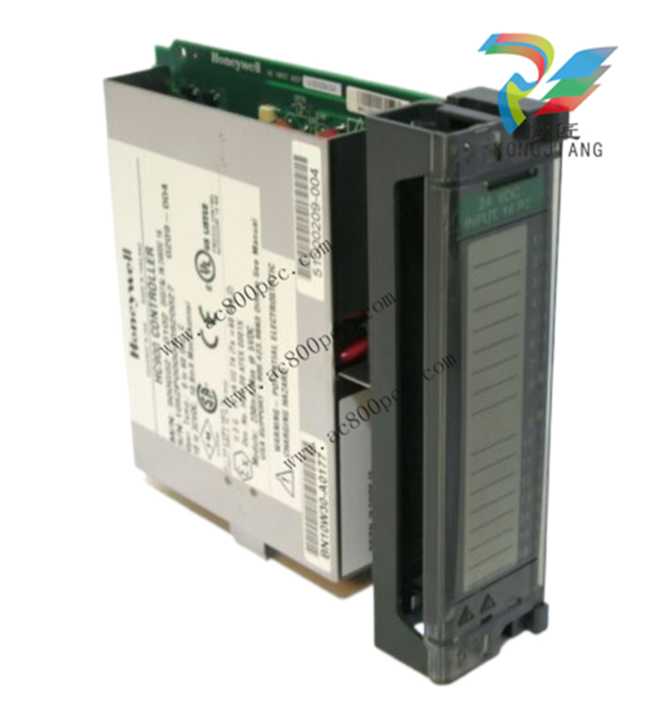
Honeywell Analog Input Remote Terminal Panel (RTP) Note 6 (NOT FOR SIL2 SYSTEMS) 900RTA-L001
*Limit 10, 4 channel Analog Output modules per I/O rack.
*Limit 4 PFQ modules per I/O rack.
Total mA @ 5V =
Total mA @ 24V=
Complete columns A, D and E above.
1. Is column D total mA @ 5V less than 2000mA? Yes/No
2. Is column E total mA @ 24V less than 900mA? Yes/No
3. If the answers to 1 and 2 are YES, go to 4. If the answer to 1 or 2 is NO, use power supply 900P01-0001.
4. Multiple column D total by 5.1
5. Multiple column E total by 24.5
6. Sum results of 4 and 5. ( )
7. Divide results of 6 by 1000 ( )
8. Is the result of 7 less than 28? Yes/No
If the answer to 8 is Yes, use power supply 900P02-0001
If the answer to 8 is No, use power supply 900P01-0001
DC Power Supply
The P24 DC power supply is for use with +24V input power applications. The wattage rating is the same as
the P01, 60W.
Rack Orientation and Mounting
Racks must be mounted as indicated in illustrations throughout this manual, so as to provide for vertical
airflow through the racks. That is, racks must never be mounted vertically, and must never be mounted
with the backplane horizontal (for example, flat on a horizontal panel or tabletop). Environmental
specifications apply only to the normal mounting configuration.
Rack dimensions, including overall dimensions and patterns for drilling holes for mounting, are given in
Figure 24 and Figure 25. Vertical spacing of racks, which is required for rack ventilation and for routing
wires, is shown in Figure 26.
Figure 24 – Rack Dimensions
Remote Termination Panels
If your controller will be mounted in a separate panel with intermediate terminations between field wiring
and controller wiring, consider using RTPs to replace the intermediate terminations. Pre-wired cable
assemblies for the RTPs eliminate the need for separate wiring terminations between the controller and the
intermediate terminal boards. For details see page 217.
Environment
The HC900 Controller must be mounted in suitable equipment enclosures. That is, all components such as
the Controller rack, I/O Racks, and the 900CS Control Station manufactured by Honeywell must be
mounted in approved furniture designed for industrial applications.
Consideration should be given to the installation so that the potential for the build-up of static electricity is
minimized or eliminated.
See Environmental Conditions and Approvals on page 210.
Heat Rise De-rating
The HC900 is rated to operate at 60o C. However, for maximum reliability, the following guidelines should
be observed for applications above 52o C.
1. Locate lower-power modules (Analog Input, Contact Input, etc) beside the Controller/Scanner Module,
and keep higher-power modules (AC Output, AC Input, etc) away from it. For power consumption of
each module, see Table 4.
2. For 240 Vac applications and temperatures above 56o C, or 264Vac, 52o C, de-rate the number of ON
inputs per AC input module. (See AC Input de-rating data, see Figure 27.)
3. Limit the number of Analog Output modules to a maximum of 10 per rack. (see Figure 28)
Table 4 – Power Applied, by Module Type
Module HC900 Hardware
Power (Watts)
Field Power
(Watts)
Total Power
(Watts)
Controller C30 and C30S 6.0 0.0 6.0
Controller C50 and C50S 6.0 0.0 6.0
Controller C70 and C70S 7.1 0.0 7.1
Controller C75 and C75S 7.8 0.0 7.8
Redundancy switch module (RSM) 0.1 0.0 0.1
Power Status Module (PSM) 0.1 0.0 0.1
Scanner 1 Port (S50/S50S) 3.9 0.0 3.9
Scanner 2 Port (S75/S75S) 5.0 0.0 5.0
Analog Input (Universal) 0.8 0.0 0.8
Analog Input (High level) 1.6 0.0 1.6
Analog Output (4 points) 5.1 0.0 5.1
Analog Output (8 pts. internal 24V) 9.4 0.0 9.4
Analog Output (8 pts. external 24V) 1.1 8.3 9.4
Analog Output (16 pts. internal 24V) 18.3 0.0 18.3
Analog Output (16 pts. external 24V) 1.7 16.6 18.3
Contact Input 1.6 0.0 1.6
Relay Output 3.0 0.0 3.0
16 pt DC In (@ 24V) 0.7 2.6 3.3
16 pt DC In (@ 32V) 0.7 5.1 5.7
32 pt DC In (@ 24V) 1.1 3.1 4.2
32 pt DC In (@ 32V) 1.1 5.1 6.2
16 pt DC Out 1.7 1.2 2.9
32 pt DC Out 1.2 1.8 3.0
AC In (@120V) 0.7 1.9 2.6
AC In (@240V) 0.7 7.7 8.3
AC/DC In 0.7 7.7 8.3
AC Out 1.1 12.0 13.1
PFQ 6.7 0.1 6.8
Cable/Wiring Distance Planning
For all installations observe the following guidelines.
Maximum length of RS-232 cabling (Controller to PC) is 50 feet (15.2 meters).
Maximum length of RS-485 cabling is 2000 feet (609.6 meters).
For Ethernet connections, cable length must be less than 100m. For greater than 100m a switch is
required. The use of Ethernet cables in excess of 100 meters and/or devices other than recommended
Switches will cause transmission delays on the I/O link which could have adverse affects on Controller
performance.
You can also use fiber optic cable for connections between the controller and a remote rack. Please refer
to HC900 specification document (51-52-03-31) for more details.
With redundant CPUs, when using 2 or more I/O racks an Ethernet switch is required between each CPU
and the I/O racks. Use Honeywell-approved switches only. (see page 215)
Maximum of 2 switches between each CPU’s I/O port and all I/O racks.
Cable lengths specified in this manual are absolute. When planning for routing of cables and wires, be
certain to include vertical and horizontal routing within cabinets, raceways, and conduits.
It is advantageous to minimize length of I/O wiring. However, it is also a good idea to locate racks (and
wiring) away from adverse environmental conditions such as sources of RFI, EMI, and away from areas
with high levels of moisture, dust, and corrosive materials.
Purchase history
| User name | Member Level | Quantity | Specification | Purchase Date |
|---|
Total 0 Record
Related products
Customer Reviews
Satisfaction :
5 Stars
No evaluation information


- other
- LTI Drives
- ADLINK
- Beckhoff
- Other Brands
- AMAT
- Iba
- PEPPERL+FUCHS
- Aerotech
- WATLOW
- MAN
- ADVANCED
- Abaco
- YOKOGAWA
- KOLLMORGEN
- MEGGITT
- kong-sberg
- METSO
- Motorola
- NI
- OEMAX
- RELIANCE
- scanlab
- schneider
- uniop
- Vibro-Meter
- Honeywell
- Rolls-Royce
- MOOG
- GE
- B&R
- Woodward
- Yaskawa
- xYCOM
- Siemens
- Emerson
- HIMA
- Bently
- ZYGO
- FOXBORO
- OMACO
- PROSOFT
- ENTERASYS
- TRICONEX
- Parker
- Lenze
- KEBA
- Alstom
- CTI
- ABB
- A-B
142

-
 ADLINK ACL-7225 ISA 16 channel relay output+16 channel isolated digital input card
 -
 ADLINK DAQ-2000 series synchronous acquisition card
 -
 ADLINK NuPRO-E330 PICMG 1.3 full-length industrial motherboard (SHB)
 -
 ADLINK ACL-8112 series multifunctional ISA acquisition card
 -
 ADLINK USB-2405 24 bit dynamic signal acquisition module
 -
 ADLINK PXIS-3320 15 slot 6U PXI chassis
 -
 ADLINK PCIe GIE7x series acquisition card
 -
 ADLINK PCIe-7856/PCIe-7853 Distributed Motion and IO Main Controller PCIe Acquisition Card
 -
 ADLINK PCI-6308 series isolated analog output board
 -
 ADLINK PCI-7432 Isolated Digital I/O Acquisition Card
 -
 ADLINK NuPRO-E72 PICMG 1.3 Full length Industrial SHB Single Board Computer
 -
 ADLINK MXE-5400 series fanless embedded industrial computer
 -
 ADLINK M-322 Industrial ATX Motherboard
 -
 ADLINK IMB-M43H Industrial ATX Motherboard
 -
 ADLINK IMB-M42H Industrial ATX Motherboard
 -
 ADLINK i915GV-INA ATX motherboard
 -
 ADLINK ETX-NR667 Embedded ETX Standard Computer Module
 -
 ADLINK ETX-BT (PATA to SATA version) User Manual
 -
 ADLINK CM1-BT1 PC/104 Single Board Computer
 -
![ADLINK cPCI-8217 [R] 3U CompactPCI VGA/LCD Display Module](https://aosspic10001.websiteonline.cn/hkw632bc8/image/image_aJXQRn.png) ADLINK cPCI-8217 [R] 3U CompactPCI VGA/LCD Display Module
ADLINK cPCI-8217 [R] 3U CompactPCI VGA/LCD Display Module -
 ADLINK AmITX-SL-G Mini ITX Embedded Motherboard
 -
 ADLINK AmITX-AL-I ultra-thin Mini ITX industrial motherboard
 -
 ADLINK NuPRO-E315 Full length PICMG 1.3 Industrial SHB Single Board Computer
 -
 ADLINK NuPRO-842 Full length PICMG 1.0 PCI/ISA Industrial Single Board Computer
 -
 ADLINK NuPRO-900A PICMG 1.2 ePCI-X Dual Xeon Industrial System Motherboard (SHB)
 -
 ADLINK cPCI-6910 series 6U CompactPCI single board computer
 -
 ADLINK cPCI-6860A 6U CompactPCI dual core single board computer with cPCI-R6860A rear adapter board
 -
 ADLINK cPCI-8168 6U CompactPCI Eight Axis Motion Control Card
 -
 ADLINK NuPRO-E340 PICMG 1.3 Industrial SHB motherboard
 -
 ADLINK NuPRO-A40H Full length PICMG1.0 Industrial Single Board Computer (SBC)
 -
 ADLINK NuPRO-852 Full length PICMG1.0 Industrial Single Board Computer
 -
 ADLINK NuPRO-841 Full length Industrial SBC
 -
 ADLINK NuPRO-590/591/592 series Socket7 full-length industrial SBC
 -
 ADLINK MXE-5500 series fanless embedded industrial computer
 -
 ADLINK MXE-200/200i Fanless Embedded Machine
 -
 ADLINK cPCI-6770 series CompactPCI CPU board
 -
 ADLINK NuPRO-A301 standard PICMG 1.0 full-length industrial SBC single board computer
 -
 ADLINK NuPRO-965 PICMG 1.3 SHB Express Full length Industrial Motherboard
 -
 ADLINK NuPRO-935A Full length PICMG1.0 Industrial Single Board Computer
 -
 ADLINK NuPRO-865 Full length Single Board Computer
 -
 ADLINK NuPRO-840 DV/LV Full Length PICMG Industrial Single Board Computer
 -
 ADLINK NuPRO-770 series full-length industrial single board computer
 -
 ADLINK NuPRO-595 series half length Socket 7 industrial motherboard
 -
 ADLINK cPCI-6840 series 6U CompactPCI single board computer
 -
 Foxboro 43AP series pneumatic indicator controller (PSS 3-1B3 A)
 -
 ADLINK cPCI-3720 Series 3U Low Power CompactPCI Single Board Computer
 -
 ADLINK NuPRO-E47, PICMG 1.3 full-length industrial SHB system motherboard
 -
 ADLINK NuPRO-E43 PICMG 1.3 full-length system motherboard
 -
 ADLINK NuPRO-780 series full-length industrial CPU board
 -
 ADLINK cPCI-6965 series 6U CPCI single board computer
 -
 ADLINK USB/LPCI/LPCIe-3488A GPIB interface card
 -
 Rittal SK 3241.700 Blue e+Fan Filter Unit
 -
 ADLINK cPCI-8168 6U CompactPCI 8-Axis Motion Control Card
 -
 ADLINK PCIe PXIe-8638 PCIe to PXIe Bus Expansion Kit
 -
 ADLINK PCIe GIE7x series acquisition card
 -
 ADLINK PCIe-7396 96 96 channel TTL digital IO card
 -
 ADLINK PCI/MPC/PXI-8164 Three in One Motion Control Card
 -
 ADLINK PCI-8154 Four Axis Pulse Motion Control Card
 -
 ADLINK PCI-8134 Four Axis Servo/Stepper Motion Control Card
 -
 ADLINK NuPRO-E42 PICMG1.3 full-length SHB motherboard
 -
 ADLINK MXC-6600 series high-performance fanless extended industrial computer
 -
 ADLINK MXC-6000 series embedded industrial control computer
 -
 ADLINK MXC-2300 series fanless expandable embedded industrial computer
 -
 ADLINK MCM-204 Independent Ethernet DAQ User Manual
 -
 ADLINK MCM-100/102 Edge IoT Platform for Machine Condition Monitoring User’s Manual
 -
 ADLINK MXC-6400 series sixth generation Core Fanless Scalable Industrial Control Computer
 -
 ADLINK Matrix Full Series Fanless Embedded Industrial Control Computers
 -
 ADLINK GIE64+4-channel PoE Gigabit Vision Capture Card
 -
 Honeywell UMS Security System Troubleshooting Guide
 -
 Honeywell Expert Series-C I/O Module
 -
 ADLINK EOS-1200 Embedded Vision Host
 -
 ADLINK DLAP-5200 series high-performance fanless AI industrial computer
 -
 ADLINK DLAP-4000 series embedded industrial control computer
 -
 ADLINK Matrix MXC-2000 Series Fanless Industrial Control Computer Specification
 -
 ADLINK DAQ -/DAQE -/PXI-2000 Series Multi functional Synchronous Acquisition Card
 -
 ADLINK cPCI-6520 6U CompactPCI Single Board Computer
 -
 ADLINK CM1-86DX3 PC/104 Single Board Computer
 -
 Honeywell DC1000 series PID temperature controller
 -
 ALSTOM MiCOM C264 Modular Substation Controller
 -
 EMERSON AMS 2140 Mechanical Health Analyzer
 -
 ADLINK NuPRO-E320 PICMG1.3 Full length Industrial Motherboard
 -
 ADLINK NuPRO-800 Series Full length Industrial SBC User Manual
 -
 ADLINK NuPRO-598 Industrial Single Board Computer
 -
 ADLINK MXC-6300 Fanless Embedded Industrial Control Computer
 -
 ADLINK Express-BASE7 User Manual
 -
 ADLINK DLAP-211 Series Fanless Edge AI Platform Specification Manual
 -
 ADLINK PCI/LPCI/LPCIe/cPCI-723X series 32 channel isolated digital I/O card
 -
 ADLINK cPCI-6965 series 6U CompactPCI single board computer
 -
 ADLINK NuDAQ 7200 series high-speed digital I/O board
 -
 Linghua ADLINK DLAP Deep Learning Acceleration Platform Product Manual
 -
 DEIF TCM-2 thyristor control module
 -
 Installation Manual for DEIF MVR-200 Series Medium Voltage Protection Device
 -
 DEIF MDR-2 multifunctional differential relay
 -
 DEIF AOM-1 Analog Output Module
 -
 DEIF AGI 400 series industrial/marine touch screen
 -
 Installation Manual for DEIF BRW-1 Marine Wing Bridge Instrument
 -
 DEIF AGC200 Quick Start Guide
 -
 DEIF AGC Multi line 2 Generator Set ControllerProduct basic information
 -
 ABB SPA-ZC 400 Ethernet Gateway Installation and Debugging Manual
 -
 ABB REM 543/545 motor generator protection device
 -
 DEIF PPU 300 controller
 -
 DEIF Delomatic 4 Offshore/Ocean Platform Dedicated Generator Power Management System DM-4
 -
 DEIF Delomatic Modular Generator Set Integrated System
 -
 DEIF AGC-4 Mk II Generator Set Controller
 -
 DEIF AGC-4 diesel generator set integrated controller
 -
 DEIF Multi line 2 Series PPU Unit Power Management (PPM) Operation Manual
 -
 DEIF Multi line 2 V2.4X Installation Manual
 -
 Beckwith M-6280 Digital Capacitor Bank Controller
 -
 Beckwith M-3311 Transformer Protection Relay
 -
 Beckwith M-3311A Transformer Integrated Protection Device
 -
 Beckwith M-3310 Transformer Integrated Protection Device Specification
 -
 Beckwith M-0359 Syncrocloser Check Plus Application Guide for Synchronous Calibration Relay
 -
 Beckwith M-0293A On Load Tap changer Controller Application Guide
 -
 DEIF GPU-3 Synchronous/Asynchronous Generator Integrated Microcomputer Protection Controller
 -
 Installation Instructions for DEIF PPM-3
 -
 Beckwith M-3520 distributed power grid connected comprehensive protection device
 -
 Beckwith M-3430 generator comprehensive protection device
 -
 Beckwith M-2293B adapter panel
 -
 Beckwith M-2001C digital on load voltage regulator controller
 -
 Beckwith M-2001B Digital On Load Voltage Regulating Controller
 -
 Beckwith M-0388/M-0389 synchronous verification relay
 -
 Beckwith M-0193B synchronous closing device
 -
 Beckwith M-0115A Transformer Parallel Balancing Module
 -
 Beckwith M-0067E on load tap changer controller
 -
 Beckwith M-4272 Digital Motor Bus Switching System
 -
 Beckwith M-3311A Transformer Integrated Protection Device
 -
 Beckwith M-3425A Generator Integrated Protection Device Manual
 -
 Basler BE1-27/BE1-59/BE1-27/59 undervoltage/overvoltage relay

K-JIANG

Add: Jimei North Road, Jimei District, Xiamen, Fujian, China
Tell:+86-15305925923