
K-WANG
+086-15305925923
Service expert in industrial control field!


Product
Article
NameDescriptionContent
Adequate Inventory, Timely Service
pursuit of excellence


Ship control system
Equipment control system
Power monitoring system
Brand
Product parameters
- Telephone:+86-15305925923
- contacts:Mr.Wang
- Email:wang@kongjiangauto.com
Description
How to make Ethernet cables
Ethernet cable (shielded Cat 5) contains 4 twisted pairs of wires and a drain wire. Each pair consists of a
solid color wire and a color wire with a white stripe.
1. Hold the cable ends and RJ45 connectors side by side as shown
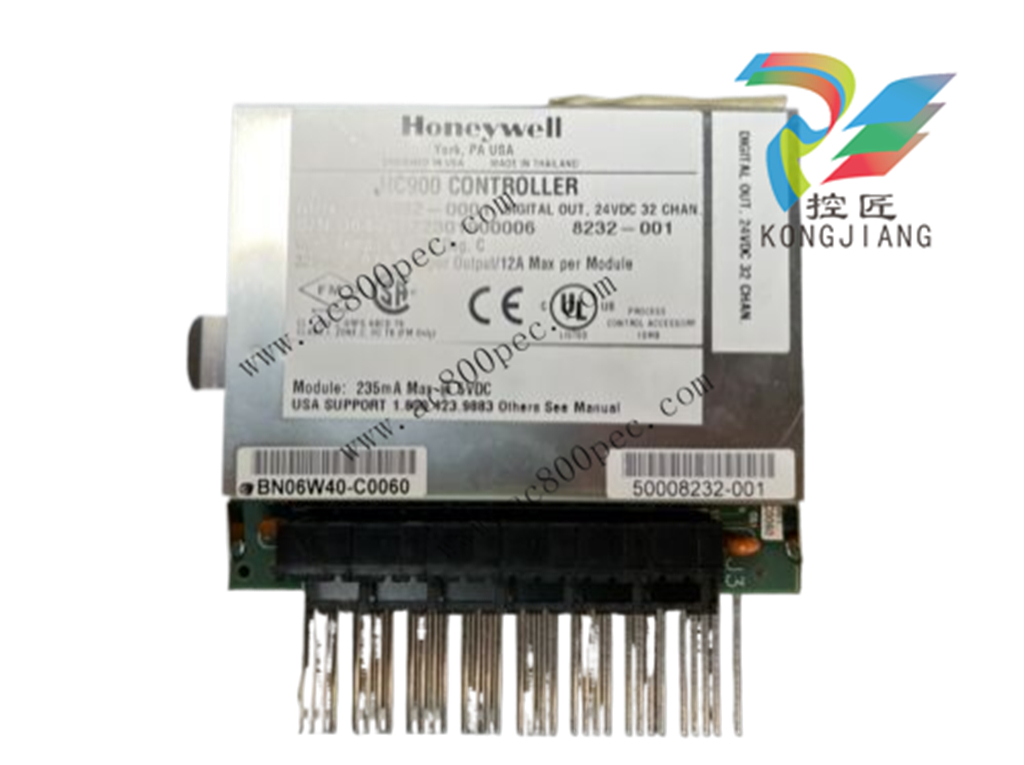
Honeywell Relay Output Remote Terminal Panel (RTP) Note 6 (NOT FOR SIL2 SYSTEMS) 900RTR-H001
2. For straight through cable, arrange wires as shown in the following table. Wires go “straight through”,no crossovers.
Straight-through cable assembly
Cable left end
Left to right
Wire color/pin number
10Base-T / 100Base-T
Signal Description
Cable right end
Left to right
Wire color/pin number
white/orange/1 Tx + white/orange/1
Orange/2 Tx - Orange/2
white/green/3 Rx + white/green/3
Blue/4 Unused Blue/4
white/blue/5 Unused white/blue/5
Green/6 Rx - Green/6
white/brown/7 Unused white/brown/7
Brown/8 Unused Brown/8
3. Crimp an RJ45 connector to each cable end. To ensure reliability do not untwist the pairs any more than
necessary to complete the crimp connection. Use care to ensure that the cable drain wire is securely
connected to the shield of the RJ45 connector when the cable is crimped. Reference the
manufacturer’s instructions.
Electrical Considerations
All racks should be mounted in an appropriate metal enclosure. A diagram that shows recommended
wiring practice for the cabinet enclosure is given in Figure 29 – Cabinet Wiring, Single Chassis, and Figure
30 – Cabinet Wiring, Multiple Chassis. When Redundant power supplies are used in Redundant controller
racks or I/O racks, separate line power sources are recommended to provide the highest level of redundancy
and system operation.
Deviations from the installation conditions specified in this manual may invalidate this product’s
conformity with Low Voltage and EMC.
Hazardous voltages exist in the equipment enclosure.
Identify and avoid contact with voltage sources.
Failure to comply with these instructions could result in death or serious injury.
Controller Grounding
PROTECTIVE BONDING (grounding) of this controller and the enclosure in which it is installed shall be
in accordance with National Electrical Code (ANSI/NFPA 70) and with local electrical codes.
Figure 29 – Cabinet Wiring, Single Chassis
For P01 power supply use 3.0A, slow-blow for 115VAC operation; 2.5A, slow-blow for 230VAC
operation. For P02 power supply, use 2.5A, slow-blow for 115VAC operation; 2.0A, slow-blow for
230VAC operation. For P24 power supply use 7.0A slow-blow.
Figure 31 – Redundant power supplies each with external fuse and switch
CE Conformity
Electrical noise produces undesirable effects in measurements and control circuits.
Digital equipment is especially sensitive to the effects of electrical noise. You should use the following
methods to reduce these effects:
Supplementary bonding of the controller enclosure to a local ground, using a No. 12 (4 mm2
) copper
conductor, is recommended. This may help minimize electrical noise and transients that may adversely
affect the system.
Separate external wiring – group connecting wires into bundles (see Table 5) and route the individual
bundles through separate conduits or metal trays.
Use shielded twisted pair cables for all Analog I/O, Process Variable, RTD, Thermocouple, dc millivolt,
low level signal, 4-20 mA, Digital I/O, and computer interface circuits. Ground shields as described in
the section I/O Module Installation and Wiring page 77.
Use suppression devices for additional noise protection. You may want to add suppression devices at the
external source. Appropriate suppression devices are commercially available.
Refer to document 51-52-05-01 How to Apply Digital Instrumentation in Severe Electrical Noise
Environments for additional installation guidance.
Grouping Wires for Routing
Wires that carry relatively high electrical energy can produce unwanted noise in wires that transmit signals
of relatively low energy, particularly when they are placed parallel in long wiring runs. Collect and bundle
wires of similar type, and route the bundle separate from bundles of other types. Table 6 provides
suggested guidelines for grouping wires.
Table 5 – Guidelines for Grouping Wires
Wire Group Wire Functions
High voltage
(>50 Vdc/Vac)
AC Line power wiring
Earth ground wiring
Control relay output wiring
Line voltage alarm wiring
Signal
(<15 Vdc)
Analog signal wire, such as:
Input signal wire (thermocouple, 4 mA to 20 mA, etc.)
4-20 mA output signal wiring
Slidewire feedback circuit wiring
Communications
Low voltage
(<50 Vdc/Vac)
Low voltage alarm relay output wiring
Low voltage wiring to solid state type control circuits
Master Control Relay
A Master Control Relay (MCR) structure is a safety mechanism for shutting down the process control
system in emergency conditions. This mechanism, which is hard-wired (provided and installed by the
User) can include several Emergency Stop switches., strategically located near process equipment. An
example of an MCR structure is given in Figure 32.
Operating any of the Emergency-Stop switches opens the holding path for the MCR. When the MCR
de-energizes, the MCR contact opens, disconnecting all AC power that is supplied to AC Input Modules
and to AC Output Modules. Notice that AC power is disconnected only from the AC input/output modules.
Power is still available to Power Supplies at the Controller Rack and at each I/O expansion rack. The
Controller Module and the Scanner Modules in the racks continue to execute diagnostics and other
programs.
The Master Control Relay does not remove power from the Controller rack or from any of the I/O
expansion racks.
Before performing service tasks such as installation of terminal connections or fuse
replacement, use the appropriate switch(s) to disconnect power from the power supply at each
module.
Ensure that wiring design precludes over-riding of the MCR by operator actions.
Failure to comply with these instructions could result in death or serious injury.
Class 1, Division 2 Installations
DO NOT REMOVE OR REPLACE MODULES WHILE CIRCUIT IS LIVE UNLESS
THE AREA IS KNOWN NOT TO CONTAIN FLAMMABLE VAPORS.
Purchase history
| User name | Member Level | Quantity | Specification | Purchase Date |
|---|
Total 0 Record
Related products
Customer Reviews
Satisfaction :
5 Stars
No evaluation information


- other
- LTI Drives
- ADLINK
- Beckhoff
- Other Brands
- AMAT
- Iba
- PEPPERL+FUCHS
- Aerotech
- WATLOW
- MAN
- ADVANCED
- Abaco
- YOKOGAWA
- KOLLMORGEN
- MEGGITT
- kong-sberg
- METSO
- Motorola
- NI
- OEMAX
- RELIANCE
- scanlab
- schneider
- uniop
- Vibro-Meter
- Honeywell
- Rolls-Royce
- MOOG
- GE
- B&R
- Woodward
- Yaskawa
- xYCOM
- Siemens
- Emerson
- HIMA
- Bently
- ZYGO
- FOXBORO
- OMACO
- PROSOFT
- ENTERASYS
- TRICONEX
- Parker
- Lenze
- KEBA
- Alstom
- CTI
- ABB
- A-B
142

-
 ADLINK PCI-9112/cPCI-9112 multifunctional acquisition card
 -
 ADLINK PCI-8102 Two Axis Pulse Motion Control Card
 -
 ADLINK PCI-9812/PCI-9810 synchronous 4-channel high-speed acquisition card
 -
 ADLINK PCI-7200/cPCI-7200 high-speed digital I/O board
 -
 ADLINK MXE-1000 series fanless embedded machine
 -
 ADLINK IMB-T10 Mini ITX Industrial Motherboard
 -
 ADLINK HSL Distributed High Speed I/O System
 -
 ADLINK PXI/DAQ/DAQe-2500 series multifunctional analog output DAQ card
 -
 ADLINK PXI/DAQ/DAQe-2200 series multifunctional data acquisition card
 -
 ADLINK ETX-AT ETX Core Computer Module
 -
 ADLINK ACL-7225 ISA 16 channel relay output+16 channel isolated digital input card
 -
 ADLINK DAQ-2000 series synchronous acquisition card
 -
 ADLINK NuPRO-E330 PICMG 1.3 full-length industrial motherboard (SHB)
 -
 ADLINK ACL-8112 series multifunctional ISA acquisition card
 -
 ADLINK USB-2405 24 bit dynamic signal acquisition module
 -
 ADLINK PXIS-3320 15 slot 6U PXI chassis
 -
 ADLINK PCIe GIE7x series acquisition card
 -
 ADLINK PCIe-7856/PCIe-7853 Distributed Motion and IO Main Controller PCIe Acquisition Card
 -
 ADLINK PCI-6308 series isolated analog output board
 -
 ADLINK PCI-7432 Isolated Digital I/O Acquisition Card
 -
 ADLINK NuPRO-E72 PICMG 1.3 Full length Industrial SHB Single Board Computer
 -
 ADLINK MXE-5400 series fanless embedded industrial computer
 -
 ADLINK M-322 Industrial ATX Motherboard
 -
 ADLINK IMB-M43H Industrial ATX Motherboard
 -
 ADLINK IMB-M42H Industrial ATX Motherboard
 -
 ADLINK i915GV-INA ATX motherboard
 -
 ADLINK ETX-NR667 Embedded ETX Standard Computer Module
 -
 ADLINK ETX-BT (PATA to SATA version) User Manual
 -
 ADLINK CM1-BT1 PC/104 Single Board Computer
 -
![ADLINK cPCI-8217 [R] 3U CompactPCI VGA/LCD Display Module](https://aosspic10001.websiteonline.cn/hkw632bc8/image/image_aJXQRn.png) ADLINK cPCI-8217 [R] 3U CompactPCI VGA/LCD Display Module
ADLINK cPCI-8217 [R] 3U CompactPCI VGA/LCD Display Module -
 ADLINK AmITX-SL-G Mini ITX Embedded Motherboard
 -
 ADLINK AmITX-AL-I ultra-thin Mini ITX industrial motherboard
 -
 ADLINK NuPRO-E315 Full length PICMG 1.3 Industrial SHB Single Board Computer
 -
 ADLINK NuPRO-842 Full length PICMG 1.0 PCI/ISA Industrial Single Board Computer
 -
 ADLINK NuPRO-900A PICMG 1.2 ePCI-X Dual Xeon Industrial System Motherboard (SHB)
 -
 ADLINK cPCI-6910 series 6U CompactPCI single board computer
 -
 ADLINK cPCI-6860A 6U CompactPCI dual core single board computer with cPCI-R6860A rear adapter board
 -
 ADLINK cPCI-8168 6U CompactPCI Eight Axis Motion Control Card
 -
 ADLINK NuPRO-E340 PICMG 1.3 Industrial SHB motherboard
 -
 ADLINK NuPRO-A40H Full length PICMG1.0 Industrial Single Board Computer (SBC)
 -
 ADLINK NuPRO-852 Full length PICMG1.0 Industrial Single Board Computer
 -
 ADLINK NuPRO-841 Full length Industrial SBC
 -
 ADLINK NuPRO-590/591/592 series Socket7 full-length industrial SBC
 -
 ADLINK MXE-5500 series fanless embedded industrial computer
 -
 ADLINK MXE-200/200i Fanless Embedded Machine
 -
 ADLINK cPCI-6770 series CompactPCI CPU board
 -
 ADLINK NuPRO-A301 standard PICMG 1.0 full-length industrial SBC single board computer
 -
 ADLINK NuPRO-965 PICMG 1.3 SHB Express Full length Industrial Motherboard
 -
 ADLINK NuPRO-935A Full length PICMG1.0 Industrial Single Board Computer
 -
 ADLINK NuPRO-865 Full length Single Board Computer
 -
 ADLINK NuPRO-840 DV/LV Full Length PICMG Industrial Single Board Computer
 -
 ADLINK NuPRO-770 series full-length industrial single board computer
 -
 ADLINK NuPRO-595 series half length Socket 7 industrial motherboard
 -
 ADLINK cPCI-6840 series 6U CompactPCI single board computer
 -
 Foxboro 43AP series pneumatic indicator controller (PSS 3-1B3 A)
 -
 ADLINK cPCI-3720 Series 3U Low Power CompactPCI Single Board Computer
 -
 ADLINK NuPRO-E47, PICMG 1.3 full-length industrial SHB system motherboard
 -
 ADLINK NuPRO-E43 PICMG 1.3 full-length system motherboard
 -
 ADLINK NuPRO-780 series full-length industrial CPU board
 -
 ADLINK cPCI-6965 series 6U CPCI single board computer
 -
 ADLINK USB/LPCI/LPCIe-3488A GPIB interface card
 -
 Rittal SK 3241.700 Blue e+Fan Filter Unit
 -
 ADLINK cPCI-8168 6U CompactPCI 8-Axis Motion Control Card
 -
 ADLINK PCIe PXIe-8638 PCIe to PXIe Bus Expansion Kit
 -
 ADLINK PCIe GIE7x series acquisition card
 -
 ADLINK PCIe-7396 96 96 channel TTL digital IO card
 -
 ADLINK PCI/MPC/PXI-8164 Three in One Motion Control Card
 -
 ADLINK PCI-8154 Four Axis Pulse Motion Control Card
 -
 ADLINK PCI-8134 Four Axis Servo/Stepper Motion Control Card
 -
 ADLINK NuPRO-E42 PICMG1.3 full-length SHB motherboard
 -
 ADLINK MXC-6600 series high-performance fanless extended industrial computer
 -
 ADLINK MXC-6000 series embedded industrial control computer
 -
 ADLINK MXC-2300 series fanless expandable embedded industrial computer
 -
 ADLINK MCM-204 Independent Ethernet DAQ User Manual
 -
 ADLINK MCM-100/102 Edge IoT Platform for Machine Condition Monitoring User’s Manual
 -
 ADLINK MXC-6400 series sixth generation Core Fanless Scalable Industrial Control Computer
 -
 ADLINK Matrix Full Series Fanless Embedded Industrial Control Computers
 -
 ADLINK GIE64+4-channel PoE Gigabit Vision Capture Card
 -
 Honeywell UMS Security System Troubleshooting Guide
 -
 Honeywell Expert Series-C I/O Module
 -
 ADLINK EOS-1200 Embedded Vision Host
 -
 ADLINK DLAP-5200 series high-performance fanless AI industrial computer
 -
 ADLINK DLAP-4000 series embedded industrial control computer
 -
 ADLINK Matrix MXC-2000 Series Fanless Industrial Control Computer Specification
 -
 ADLINK DAQ -/DAQE -/PXI-2000 Series Multi functional Synchronous Acquisition Card
 -
 ADLINK cPCI-6520 6U CompactPCI Single Board Computer
 -
 ADLINK CM1-86DX3 PC/104 Single Board Computer
 -
 Honeywell DC1000 series PID temperature controller
 -
 ALSTOM MiCOM C264 Modular Substation Controller
 -
 EMERSON AMS 2140 Mechanical Health Analyzer
 -
 ADLINK NuPRO-E320 PICMG1.3 Full length Industrial Motherboard
 -
 ADLINK NuPRO-800 Series Full length Industrial SBC User Manual
 -
 ADLINK NuPRO-598 Industrial Single Board Computer
 -
 ADLINK MXC-6300 Fanless Embedded Industrial Control Computer
 -
 ADLINK Express-BASE7 User Manual
 -
 ADLINK DLAP-211 Series Fanless Edge AI Platform Specification Manual
 -
 ADLINK PCI/LPCI/LPCIe/cPCI-723X series 32 channel isolated digital I/O card
 -
 ADLINK cPCI-6965 series 6U CompactPCI single board computer
 -
 ADLINK NuDAQ 7200 series high-speed digital I/O board
 -
 Linghua ADLINK DLAP Deep Learning Acceleration Platform Product Manual
 -
 DEIF TCM-2 thyristor control module
 -
 Installation Manual for DEIF MVR-200 Series Medium Voltage Protection Device
 -
 DEIF MDR-2 multifunctional differential relay
 -
 DEIF AOM-1 Analog Output Module
 -
 DEIF AGI 400 series industrial/marine touch screen
 -
 Installation Manual for DEIF BRW-1 Marine Wing Bridge Instrument
 -
 DEIF AGC200 Quick Start Guide
 -
 DEIF AGC Multi line 2 Generator Set ControllerProduct basic information
 -
 ABB SPA-ZC 400 Ethernet Gateway Installation and Debugging Manual
 -
 ABB REM 543/545 motor generator protection device
 -
 DEIF PPU 300 controller
 -
 DEIF Delomatic 4 Offshore/Ocean Platform Dedicated Generator Power Management System DM-4
 -
 DEIF Delomatic Modular Generator Set Integrated System
 -
 DEIF AGC-4 Mk II Generator Set Controller
 -
 DEIF AGC-4 diesel generator set integrated controller
 -
 DEIF Multi line 2 Series PPU Unit Power Management (PPM) Operation Manual
 -
 DEIF Multi line 2 V2.4X Installation Manual
 -
 Beckwith M-6280 Digital Capacitor Bank Controller
 -
 Beckwith M-3311 Transformer Protection Relay
 -
 Beckwith M-3311A Transformer Integrated Protection Device
 -
 Beckwith M-3310 Transformer Integrated Protection Device Specification
 -
 Beckwith M-0359 Syncrocloser Check Plus Application Guide for Synchronous Calibration Relay
 -
 Beckwith M-0293A On Load Tap changer Controller Application Guide
 -
 DEIF GPU-3 Synchronous/Asynchronous Generator Integrated Microcomputer Protection Controller
 -
 Installation Instructions for DEIF PPM-3
 -
 Beckwith M-3520 distributed power grid connected comprehensive protection device
 -
 Beckwith M-3430 generator comprehensive protection device
 -
 Beckwith M-2293B adapter panel

K-JIANG

Add: Jimei North Road, Jimei District, Xiamen, Fujian, China
Tell:+86-15305925923