

K-WANG


- Telephone:+86-15305925923
- contacts:Mr.Wang
- Email:wang@kongjiangauto.com
This chapter provides an overview of the Helicon X3 system and a technical description of the main components that give the required knowledge about the system.The figures, drawings and text in this chapter are general and may not comply to the actual installation on the vessel. For details on the delivered equipment, see chapter 4 Delivery Specification.
Rolls-Royce Helicon X3 P&T Control System
3 Design 3.1 Lever Each thruster has its own lever. Their main functions are: • Control of pitch, RPM and azimuth direction (dependant of application) • In operation • Command transfer • Lever in command • Back-up control • Alarm The control lever has integrated buttons and indication lamps for command transfer, backup system on/off, alarm indication/buzzer and push button for reset of buzzer. The display in the base shows set command (pitch and direction) from the lever. The lever contains two redundant electronic circuits, one for the normal control system and one for the backup system
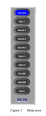
There is one command page for each thruster, in addition to one system overview page and one alarm page. The overview page shows the most essential information for all thrusters, but to activate functions or to view all available information for a thruster, the particular thrusters' page must be selected. The graphical design is based on the following principles: • All functions pages are only one click away • Large and simple buttons which are easy to read. • Same design theme for all clickable objects. • To avoid unintentional activation of functions, all function activation buttons require press on the accept button to proceed.
Indicators The indicators give feedback on various data and can be found on the bridge and in the engine control room. There are three main types of indicators: • Azimuth indicator • RPM indicator • Pitch indicator In addition a bridge order indicator may be delivered on some vessels. 3.5 Viewcon Network cabinet The network cabinet(s) contains several switches. The network cabinet(s) connects the panel PCs and the controller cabinets. Network Operator stations and electronic units are linked together in an Ethernet network. The network is single and may contain several separate switches. (CAN bus is the internal communication between levers, I/O modules and Marine Controller.)
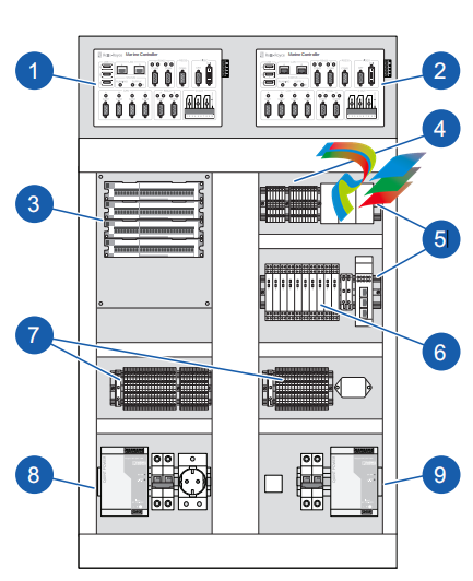
Controller cabinet Usually located on bridge or in instrument room. This cabinet distributes signals to and from the bridge and ECR. It controls all the signals from the Helicon X3 and send them to the I/O cabinet. There is one controller cabinet per propeller/thruster. Communicates with the I/O cabinet located in the thruster room. 1. Rolls-Royce Marine Controller (Normal) 2. Rolls-Royce Marine Controller (Backup) 3. I/O modules 4. Power distribution 5. Network switches and terminals 6. Signal isolation amplifiers (optional) 7. Power Distribution 8. Main power supply (AC) / fuses 9. Backup power supply (DC) / fuses 3.7 I/O Cabinet The I/O cabinet is often located in the thruster room near sensors and actuators. This cabinet distributes signals to the different propulsion/thruster units. There is one I/O unit per propeller/thruster. The I/O cabinet sends signals to the actuators on the propellers/thrusters and receives signals from the sensors. There is CAN bus communication between each I/O and controller cabinet.
1. I/O modules 2. Capacitors (optional) 3. Power distribution 4. Power distribution 5. Power / network / CANBus terminals 6. Local panel connection 7. Actuator interface card(s) (optional) 8. Relays (optional) 9. Signal isolation amplifiers (optional) 10. I/O terminals 4 Functions Tunnel Thruster Control Functions The control functions included in the Tunnel Thruster Control system: • Pitch control • Command transfer Main Propulsion Azimuth Control Functions The control functions included in the Main Propulsion Azimuth Control system: • RPM control • Azimuth control • Command transfer 4.1 Pitch Control The function of the pitch controller is to move the propeller blades in accordance to the control lever order. The actuator unit represents the interface between the remote control and the main servo system, which performs the actual positioning of the blades.
| User name | Member Level | Quantity | Specification | Purchase Date |
|---|


- LTI Drives
- other
- ADLINK
- Beckhoff
- Shinkawa
- Other Brands
- AMAT
- Iba
- PEPPERL+FUCHS
- Aerotech
- WATLOW
- MAN
- ADVANCED
- Abaco
- YOKOGAWA
- KOLLMORGEN
- MEGGITT
- kong-sberg
- METSO
- Motorola
- NI
- OEMAX
- RELIANCE
- scanlab
- schneider
- uniop
- Vibro-Meter
- Honeywell
- Rolls-Royce
- MOOG
- GE
- B&R
- Woodward
- Yaskawa
- xYCOM
- Siemens
- Emerson
- HIMA
- Bently
- ZYGO
- FOXBORO
- OMACO
- PROSOFT
- ENTERASYS
- TRICONEX
- Parker
- Lenze
- KEBA
- Alstom
- CTI
- ABB
- A-B

-
 SIGMATEK TAE 1941 Touch Display Unit
 -
 SIGMATEK TAE 151 Touch Display Unit
 -
 SIGMATEK AKM series servo motor
 -
 SIGMATEK S-DIAS Control System
 -
 SIGMATEK Human Machine Interface (HMI)
 -
 SIGMATEK DIAS Drive 310-23 servo amplifier
 -
 SIGMATEK CCP 521 C-DIAS processor module
 -
 MEGMEET L6 series electric drive
 -
 Sysmex XN-1000/XN-2000 Hematology Analyzer
 -
 Sysmex XN-L series (XN-530/XN-430/XN-330) fully automatic blood cell analyzer
 -
 Sysmex XN-9000 Series Fully Automated Blood Analysis Pipeline
 -
 LTI‑Motion ServoOne Field Bus Systems PROFIBUS and PROFINET
 -
 Micro Innovation MICRO PANEL GF1 Color Touch Human Computer Interface
 -
 Micro Innovation WINbloc Distributed Remote I/O System
 -
 Micro Innovation MICRO PANEL GS-2 Industrial Touch Visualization Operation Panel (HMI)
 -
 LTi LST/LSH series synchronous servo motor
 -
 LTi CDE/CDB3000 positioning controller
 -
 ENOTEC SILOTEC ® Installation and Operation Instructions for 8000 Silo Monitoring O ₂/CO ₑ Analyzer System
 -
 ENOTEC ENSITU ® 7000 Compact Oxygen Transmitter Probe
 -
 ENOTEC COMTEC ® Installation and Operation Instructions for 6000 ATEX GasEx Explosion proof O ₂/COE Analyzer System
 -
 ENOTEC Integrated Products
 -
 ENOTEC OXITEC ® 500E Extraction Oxygen Analyzer
 -
 KUKA KR CS Box-2 Compact Controller for Four Axis SCARA Robot
 -
 KUKA KR C5 slim-2 Robot Controller
 -
 KUKA KR C5 micro With KUKA System Software (KSS/VSS) Assembly Instructions
 -
 KUKA KR C5 micro controller
 -
 KUKA KR C5 Controller Assembly Instructions
 -
 KUKA KR C5 compactcab and KR C5 small-size cab cabinets
 -
 KUKA KR C4 smallsize-2 small robot control cabinet
 -
 KUKA KR C4 Midsize/KR C4 Midsize CK Assembly Manual
 -
 ENOTEC ® Installation and Operation Instructions for 5000/5000+Oxygen Analyzer System
 -
 KUKA KR C4 extended; KR C4 extended CK Assembly Instructions Assembly Manual
 -
 Assembly/Installation Manual for KUKA KR C4 Compact Control Cabinet
 -
 KUKA Sunrise Cabinet Med Medical Collaborative Robot Special Control Cabinet
 -
 KUKA Sunrise Cabinet Next Generation Small Control Cabinet
 -
 KUKA KR C4 Smallsize-2 family's smallest control cabinet
 -
 KUKA KR C4 midsize; KR C4 midsize CK medium-sized control cabinet
 -
 KUKA KR C4 extended is a high-power multi axis control cabinet
 -
 General installation and operation instructions for KUKA KR C4 and KR C4 CK controllers
 -
 KUKA KR C4 compact controller operation instructions
 -
 Installation and Operation Instructions for KUKA Robot Arm
 -
 KUKA TITAN-2 Ultra Ground Overloading Six Axis Robot
 -
 Assembly instructions for KUKA KR SCARA-2 CS series robotic arm body
 -
 KUKA MA KR SCARA X Installation Guide
 -
 KUKA KR FORTEC-2 Ultra Heavy duty Ground Six Axis Robot Mechanical Assembly Manual
 -
 KUKA KR FORTEC-2 new generation heavy-duty ground six axis robot
 -
 KUKA Robots KR 1000 titan; KR 1000 L750 titan With F Variants Assembly Instructions
 -
 KUKA KR 600 FORTEC heavy-duty six axis ground mounted industrial robot
 -
 KUKA KR 500 MT FORTEC Heavy duty Six Axis Industrial Robot
 -
 KUKA KR 360 FORTEC Heavy duty Six Axis Industrial Robot
 -
 KUKA Sunrise Cabinet Med Medical Edition Robot Controller User Manual
 -
 KUKA Robots KR SCARA HO Assembly Instructions
 -
 KUKA Robots KR QUANTEC-2 PA Assembly Instructions
 -
 KUKA Robots KR QUANTEC-2 K and KR QUANTEC-2 P With K-F and P-C Variants Assembly Instructions
 -
 KUKA Robots KR QUANTEC-2 HO Assembly Instructions
 -
 KUKA Robots KR QUANTEC-2 HC Assembly Instructions
 -
 KUKA KR QUANTEC-2 series heavy-duty ground mounted six axis industrial robot
 -
 KUKA KR QUANTEC PA series heavy-duty palletizing robot
 -
 KUKA KR IONTEC-2 series six axis industrial robot
 -
 KUKA KR IONTEC ultra series six axis heavy-duty industrial robot
 -
 KUKA KR IONTEC HO Robot Assembly Manual
 -
 KUKA Robots KR CYBERTECH-3 HW Assembly Instructions
 -
 KUKA Robots KR CYBERTECH-3 Assembly Instructions
 -
 KUKA Robots KR CYBERTECH-2 arc Assembly Instructions
 -
 KUKA Robots KR CYBERTECH nano-2 Assembly Instructions
 -
 KUKA KR CYBERTECH CR HO (KR 20 R1810-HO) assembly instructions
 -
 KUKA Robots KR CYBERTECH With F variant Assembly Instructions
 -
 KUKA KR CYBERTECH CR (KR 20 R1810-CR) Clean Room (CR) Version 6-Axis Industrial Robot
 -
 KUKA KR AGILUS-3 ultra series small six axis serial robot
 -
 KUKA KR 300 R2700-2 C-F Cast Ceiling Mounted 6-Axis Heavy duty Industrial Robot
 -
 KUKA KR 20 R1820-2 E Six Axis Industrial Robot
 -
 Assembly instructions for KUKA KR AGILUS-3 small six axis robot
 -
 KUKA KR AGILUS-2 New Generation Small Six Axis Robot
 -
 KUKA KR 1000 1300 titan PA; KR 1000 L950 titan PA With F Variants Assembly Instructions
 -
 KUKA KR 700 PA/KR 700 PA Arctic Installation Guide
 -
 KUKA KR 18 R1450-3 PP six axis ground mounted industrial robot
 -
 KUKA 12 SCARA Series 4-axis SCARA Horizontal Joint Robot
 -
 KUKA KR 4 R600 Small Six Axis Industrial Robot
 -
 Installation Guide for KUKA KR 3 R540 Small 6-Axis Industrial Robot
 -
 KUKA LBR iiwa CR Clean 7-Axis Lightweight Collaborative Robot
 -
 KUKA KR AGILUS sixx series six axis industrial robot operation instructions
 -
 KUKA 4-axis heavy-duty SCARA horizontal multi joint robot KR 60 R1200 Z400 CS
 -
 KUKA KR 23 SCARA-2 CS SCARA Horizontal Multi Joint Robot
 -
 KUKA KR 20 SCARA CS Robot Assembly Instructions
 -
 KUKA KR 15 DELTA-2 Assembly Manual
 -
 KUKA KR 13 SCARA-2 CS Assembly Manual
 -
 KUKA KR 3 D1200 (Standard Delta Robot) Assembly Instructions
 -
 KUKA KR 3 D1200 HM Assembly Manual
 -
 KUKA LBR Med 7 R800, LBR Med 14 R820 Medical Edition Robot
 -
 KUKA Robots LBR iiwa 7 R800, LBR iiwa 14 R820 Operating instructions
 -
 KUKA LBR iiwa CR (Clean Room Version Robot) Operating Instructions
 -
 Lauer PCStopline series text operation panel
 -
 KUKA LBR iisy (MA_LBR_iisy V5) assembly manual
 -
 KUKA LBR iisy 3 R760 Assembly Manual
 -
 KUKA LBR iico Collaborative Robot Assembly Manual
 -
 Lauer LCAstarline (LCA300/LCA320/LCA325) Text Display Screen
 -
 Lauer PCS950/PCS950c/PCS950e operation console
 -
 Lauer EPC Series Industrial Embedded Human Computer Integrated PC User Guide
 -
 Bonfiglioli Precision Planetary Gearbox TIR-STD ENG R07
 -
 Bonfiglioli ACT/ACU Cold Plate Inverter Installation Instructions
 -
 Bonfiglioli EM-RES-02 Expansion Module
 -
 Bonfiglioli EM-RES-01 Expansion Module
 -
 Bonfiglioli EM-IO-04 Expansion Module
 -
 Bonfiglioli EM-IO-03 Expansion Module
 -
 Bonfiglioli EM-IO-02 Expansion Module
 -
 Bonfiglioli Vectron EM-IO-01 Expansion Module
 -
 Bonfiglioli F series gearbox
 -
 Installation, operation, maintenance, and spare parts of Bonfiglioli HF series reducers
 -
 Installation, Operation, and Maintenance of Bonfiglioli 300-300M Series ATEX Reducer
 -
 Bonfiglioli R3 series planetary gearbox
 -
 Bonfiglioli C series inline helical gear explosion-proof reducer
 -
 Bonfiglioli EM-ENC-05 Expansion Module
 -
 Bonfiglioli EM-ENC-04 Expansion Module
 -
 Bonfiglioli EM-ENC-03 Expansion Module
 -
 Bonfiglioli EM-ENC-02 Expansion Module
 -
 Bonfiglioli CM-CAN CANopen communication module
 -
 Bonfiglioli EM-SYS System Bus Expansion Module
 -
 Bonfiglioli CM-PDP Profibus DP Communication Module
 -
 Bonfiglioli CM-232/CM-485/CM-485T Modbus Communication Manual
 -
 Bonfiglioli BMS series precision planetary servo reduction motor
 -
 Bonfiglioli ACTION series ACT210 (230V), ACT410 (400V) frequency converter operation manual
 -
 Bonfiglioli ACT series frequency converter
 -
 Bonfiglioli HDP/HDO series gear unit IOM installation, operation and maintenance instructions
 -
 Installation, operation, and maintenance of Bonfiglioli 300-300M series reducers
 -
 Bonfiglioli 300M Modular planetary gearboxe
 -
 Bonfiglioli 3/H series heavy-duty modular gearbox
 -
 Bonfiglioli KRG-KCG-KSD hydraulic coupling
 -
 Bonfiglioli Vectron BTD-BCR servo motor

K-JIANG

Add: Jimei North Road, Jimei District, Xiamen, Fujian, China
Tell:+86-15305925923