
K-WANG


- Telephone:+86-15305925923
- contacts:Mr.Wang
- Email:wang@kongjiangauto.com
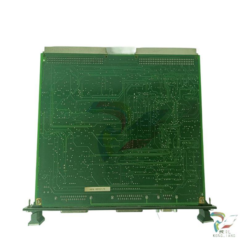
GE VMIVME-3125* Analog Input Board
GE VMIVME-3125* Analog Input Board
DESCRIPTION
The VMIVME-3125* Analog Input boards provide automatic scanning of 16 differential or 32 single-ended analog input channels. The channels are digitized with a 12-bit resolution Analog-to-Digital Converter (ADC). Each input is overvoltage protected and low-pass filtered. The board is very easy to use, no software setup is required. After powerup or system reset, the VMIVME-3125 automatically starts scanning each of its 16 or 32 input channels. Conversion data is stored automatically in a dual-port memory, making it immediately accessible from the VMEbus. The VMIVME-3125 provides on-board voltage references to perform an on-line or off-line built-in self-test. The input voltage range and gain are user-programmable with jumpers. The VMEbus base address and the access mode are fully selectable.
Features
Some of the distinguishing features of the VMIVME-3125 include:
• VMEbus 6U single height format
• 16 differential or 32 single-ended analog input channels
• One 12-bit A/D converter with built-in track-and-hold
• Automatic scanning of all inputs at 40 kHz aggregate rate
• No software initialization required to begin scanning
• Input ranges from ±50 mV to ±10 VDC
• Input overvoltage protection
• Analog inputs are low-pass filtered at 50 kHz
• Optional add on 40 Hz low-pass filter daughter board
• Discrete wire or mass terminated cables
• Input pull-down resistors prevent floating inputs
• Supports on-line and off-line Built-In-Test (BIT)
• Jumper programmable gains of x1, x10, x100
• Selectable A/D ranges of ±5 VDC, ±10 VDC and 0 to 10 VDC
• Data Accesses: D16, D08(EO), D08(O)
• Front panel LED
• 1,000 VDC isolation between analog and digital ground
• Optional 0 - 20, 4 - 20, and 5 - 25 mA current input ranges
Safety Summary
The following general safety precautions must be observed during all phases of the operation, service and repair of this product. Failure to comply with these precautions or with specific warnings elsewhere in this manual violates safety standards of design, manufacture and intended use of this product.
Ground the System
To minimize shock hazard, the chassis and system cabinet must be connected to an electrical ground. A three-conductor AC power cable should be used. The power cable must either be plugged into an approved three-contact electrical outlet or used with a three-contact to two-contact adapter with the grounding wire (green) firmly connected to an electrical ground (safety ground) at the power outlet.
Keep Away from Live Circuits
Operating personnel must not remove product covers. Component replacement and internal adjustments must be made by qualified maintenance personnel. Do not replace components with power cable connected. Under certain conditions, dangerous voltages may exist even with the power cable removed. To avoid injuries, always disconnect power and discharge circuits before touching them.
| User name | Member Level | Quantity | Specification | Purchase Date |
|---|


- other
- ADLINK
- LTI Drives
- Other Brands
- AMAT
- Iba
- PEPPERL+FUCHS
- Aerotech
- WATLOW
- MAN
- ADVANCED
- Abaco
- YOKOGAWA
- KOLLMORGEN
- MEGGITT
- kong-sberg
- METSO
- Motorola
- NI
- OEMAX
- RELIANCE
- scanlab
- schneider
- uniop
- Vibro-Meter
- Honeywell
- Rolls-Royce
- MOOG
- GE
- B&R
- Woodward
- Yaskawa
- xYCOM
- Siemens
- Emerson
- HIMA
- Bently
- ZYGO
- FOXBORO
- OMACO
- PROSOFT
- ENTERASYS
- TRICONEX
- Parker
- Lenze
- KEBA
- Alstom
- CTI
- ABB
- A-B

-
 ADLINK NuPRO-865 Full length Single Board Computer
 -
 ADLINK NuPRO-840 DV/LV Full Length PICMG Industrial Single Board Computer
 -
 ADLINK NuPRO-770 series full-length industrial single board computer
 -
 ADLINK NuPRO-595 series half length Socket 7 industrial motherboard
 -
 ADLINK cPCI-6840 series 6U CompactPCI single board computer
 -
 Foxboro 43AP series pneumatic indicator controller (PSS 3-1B3 A)
 -
 ADLINK cPCI-3720 Series 3U Low Power CompactPCI Single Board Computer
 -
 ADLINK NuPRO-E47, PICMG 1.3 full-length industrial SHB system motherboard
 -
 ADLINK NuPRO-E43 PICMG 1.3 full-length system motherboard
 -
 ADLINK NuPRO-780 series full-length industrial CPU board
 -
 ADLINK cPCI-6965 series 6U CPCI single board computer
 -
 ADLINK USB/LPCI/LPCIe-3488A GPIB interface card
 -
 Rittal SK 3241.700 Blue e+Fan Filter Unit
 -
 ADLINK cPCI-8168 6U CompactPCI 8-Axis Motion Control Card
 -
 ADLINK PCIe PXIe-8638 PCIe to PXIe Bus Expansion Kit
 -
 ADLINK PCIe GIE7x series acquisition card
 -
 ADLINK PCIe-7396 96 96 channel TTL digital IO card
 -
 ADLINK PCI/MPC/PXI-8164 Three in One Motion Control Card
 -
 ADLINK PCI-8154 Four Axis Pulse Motion Control Card
 -
 ADLINK PCI-8134 Four Axis Servo/Stepper Motion Control Card
 -
 ADLINK NuPRO-E42 PICMG1.3 full-length SHB motherboard
 -
 ADLINK MXC-6600 series high-performance fanless extended industrial computer
 -
 ADLINK MXC-6000 series embedded industrial control computer
 -
 ADLINK MXC-2300 series fanless expandable embedded industrial computer
 -
 ADLINK MCM-204 Independent Ethernet DAQ User Manual
 -
 ADLINK MCM-100/102 Edge IoT Platform for Machine Condition Monitoring User’s Manual
 -
 ADLINK MXC-6400 series sixth generation Core Fanless Scalable Industrial Control Computer
 -
 ADLINK Matrix Full Series Fanless Embedded Industrial Control Computers
 -
 ADLINK GIE64+4-channel PoE Gigabit Vision Capture Card
 -
 Honeywell UMS Security System Troubleshooting Guide
 -
 Honeywell Expert Series-C I/O Module
 -
 ADLINK EOS-1200 Embedded Vision Host
 -
 ADLINK DLAP-5200 series high-performance fanless AI industrial computer
 -
 ADLINK DLAP-4000 series embedded industrial control computer
 -
 ADLINK Matrix MXC-2000 Series Fanless Industrial Control Computer Specification
 -
 ADLINK DAQ -/DAQE -/PXI-2000 Series Multi functional Synchronous Acquisition Card
 -
 ADLINK cPCI-6520 6U CompactPCI Single Board Computer
 -
 ADLINK CM1-86DX3 PC/104 Single Board Computer
 -
 Honeywell DC1000 series PID temperature controller
 -
 ALSTOM MiCOM C264 Modular Substation Controller
 -
 EMERSON AMS 2140 Mechanical Health Analyzer
 -
 ADLINK NuPRO-E320 PICMG1.3 Full length Industrial Motherboard
 -
 ADLINK NuPRO-800 Series Full length Industrial SBC User Manual
 -
 ADLINK NuPRO-598 Industrial Single Board Computer
 -
 ADLINK MXC-6300 Fanless Embedded Industrial Control Computer
 -
 ADLINK Express-BASE7 User Manual
 -
 ADLINK DLAP-211 Series Fanless Edge AI Platform Specification Manual
 -
 ADLINK PCI/LPCI/LPCIe/cPCI-723X series 32 channel isolated digital I/O card
 -
 ADLINK cPCI-6965 series 6U CompactPCI single board computer
 -
 ADLINK NuDAQ 7200 series high-speed digital I/O board
 -
 Linghua ADLINK DLAP Deep Learning Acceleration Platform Product Manual
 -
 DEIF TCM-2 thyristor control module
 -
 Installation Manual for DEIF MVR-200 Series Medium Voltage Protection Device
 -
 DEIF MDR-2 multifunctional differential relay
 -
 DEIF AOM-1 Analog Output Module
 -
 DEIF AGI 400 series industrial/marine touch screen
 -
 Installation Manual for DEIF BRW-1 Marine Wing Bridge Instrument
 -
 DEIF AGC200 Quick Start Guide
 -
 DEIF AGC Multi line 2 Generator Set ControllerProduct basic information
 -
 ABB SPA-ZC 400 Ethernet Gateway Installation and Debugging Manual
 -
 ABB REM 543/545 motor generator protection device
 -
 DEIF PPU 300 controller
 -
 DEIF Delomatic 4 Offshore/Ocean Platform Dedicated Generator Power Management System DM-4
 -
 DEIF Delomatic Modular Generator Set Integrated System
 -
 DEIF AGC-4 Mk II Generator Set Controller
 -
 DEIF AGC-4 diesel generator set integrated controller
 -
 DEIF Multi line 2 Series PPU Unit Power Management (PPM) Operation Manual
 -
 DEIF Multi line 2 V2.4X Installation Manual
 -
 Beckwith M-6280 Digital Capacitor Bank Controller
 -
 Beckwith M-3311 Transformer Protection Relay
 -
 Beckwith M-3311A Transformer Integrated Protection Device
 -
 Beckwith M-3310 Transformer Integrated Protection Device Specification
 -
 Beckwith M-0359 Syncrocloser Check Plus Application Guide for Synchronous Calibration Relay
 -
 Beckwith M-0293A On Load Tap changer Controller Application Guide
 -
 DEIF GPU-3 Synchronous/Asynchronous Generator Integrated Microcomputer Protection Controller
 -
 Installation Instructions for DEIF PPM-3
 -
 Beckwith M-3520 distributed power grid connected comprehensive protection device
 -
 Beckwith M-3430 generator comprehensive protection device
 -
 Beckwith M-2293B adapter panel
 -
 Beckwith M-2001C digital on load voltage regulator controller
 -
 Beckwith M-2001B Digital On Load Voltage Regulating Controller
 -
 Beckwith M-0388/M-0389 synchronous verification relay
 -
 Beckwith M-0193B synchronous closing device
 -
 Beckwith M-0115A Transformer Parallel Balancing Module
 -
 Beckwith M-0067E on load tap changer controller
 -
 Beckwith M-4272 Digital Motor Bus Switching System
 -
 Beckwith M-3311A Transformer Integrated Protection Device
 -
 Beckwith M-3425A Generator Integrated Protection Device Manual
 -
 Basler BE1-27/BE1-59/BE1-27/59 undervoltage/overvoltage relay
 -
 Basler AVC63-12/AVC125-10 excitation voltage regulator
 -
 Basler L301kc Color Three Line Array Camera Operation Manual
 -
 Basler CBS 212A Current Enhanced Excitation System
 -
 Basler BE3-25 synchronous check relay
 -
 Operation Manual for Basler BE1-32R/BE1-32O/U Direction Power Relay
 -
 Basler Electric PRS-250 Veri Sync Synchronous Relay
 -
 Basler Pilot Series Area Array Industrial Camera piA2400-17gc
 -
 Basler BE1-11g comprehensive protection device for generator
 -
 Basler VR63-4C/UL Analog Excitation Voltage Regulator
 -
 Basler BE1-DFPR distribution feeder protection relay
 -
 Basler CBS310/CBS320 current strong excitation system
 -
 Basler UFOV250A/UFOV260A Low Frequency Overvoltage Module
 -
 Basler MVC104/MVC108/MVC232 manual voltage control device
 -
 Basler XR2002/XR2002F PMG excitation regulator
 -
 Basler DECS-400 Digital Excitation Control System
 -
 Basler DGC-2020 Digital Generator Set Controller
 -
 Basler MVC-300 Electronic Manual Excitation Controller
 -
 Basler MVC-104/MVC-108/MVC-232 manual excitation controller
 -
 Basler SSR32-12/SSR63-12/SSR125-12 Static Excitation Voltage Regulator
 -
 Basler SR4A/SR8A Analog Excitation Voltage Regulator
 -
 Basler BE2000E Digital Excitation Voltage Regulator
 -
 Basler DECS-2100 Digital Excitation System
 -
 Basler BE1-851 Overcurrent Protection Device Manual
 -
 Basler APR 63-5 Voltage Regulator
 -
 Basler BE1-FLEX Integrated Protection Control System
 -
 Basler BE1-700V digital voltage protection relay
 -
 Basler BE1-87B high impedance bus differential relay
 -
 Basler BE1-40Q demagnetization relay
 -
 Basler BE1-60 Voltage Balance Relay
 -
 Basler BE1-47N negative sequence voltage phase sequence relay
 -
 Basler BE1-81O/U digital frequency relay
 -
 Basler BE1-11f Feedline Integrated Protection Device Manual
 -
 Basler DECS-250 Digital Excitation Control System
 -
 Basler DECS-100 Digital Excitation Control System
 -
 Basler BE1-BPR Circuit Breaker Protection Relay
 -
 Basler BE1-50/51B-255 overcurrent relay
 -
 Basler BE1-25 synchronous check relay
 -
 Basler BE1-51 microcomputer time limited overcurrent relay
 -
 Basler DECS-300 Digital Excitation Control System

K-JIANG

Add: Jimei North Road, Jimei District, Xiamen, Fujian, China
Tell:+86-15305925923