
K-WANG


- Telephone:+86-15305925923
- contacts:Mr.Wang
- Email:wang@kongjiangauto.com
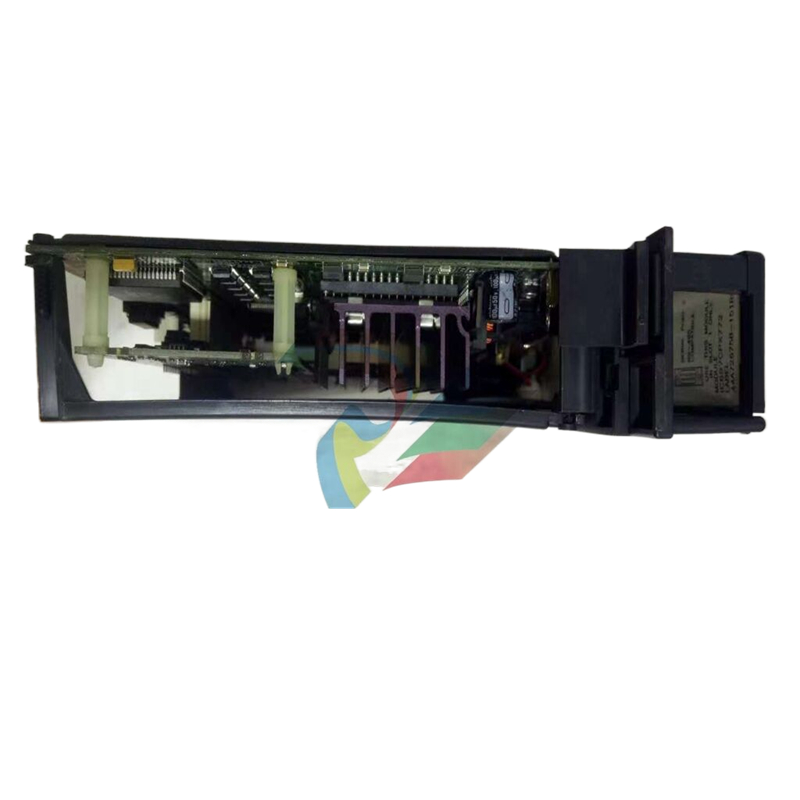
GE VMIVME-4105 Digital-to-Analog Converter Board
GE VMIVME-4105 Digital-to-Analog Converter Board
Analog Output Testing:
Any one of the eight analog outputs may be switched to the analog output test bus (Test Bus 2). This bus is routed through the P2 AMXbus analog backplane to an Analog-to-Digital Converter (ADC) board which is used to verify each DAC channel on the VMIVME-4105 board.
Compatibility:
The VMIVME-4105 Analog Output Board is a standard, double height, printed circuit board which is compatible with the VMEbus specification.
Board Address:
The physical address for the board may be selected through a 12-bit DIP switch. VMEbus address lines A04 through A15 are decoded for board selection.
Test Mode:
The DAC board may be used in conjunction with other VMIC boards and the VMIC AMXbus™ backplane for extensive fault detection and isolation. There are two dedicated analog buses that are used by the DAC board.
Tests may be performed by utilizing any one of the eight DAC outputs. While in a test mode the eight DAC outputs may be isolated from the P3 connector so that user-connected devices are not affected by worst-case testing in an off-line mode. Real-time fault detection and isolation is not supported if the multiplying DAC option is used. Built-in-Test is not supported if P2 outputs are used.
Analog Input Test Mode:
Any one of the eight analog outputs may be switched to an analog test bus (Test Bus 1). This analog bus may be used to verify the operation of a VMIC Multiplexer Expansion Board (VMIVME-3200A) that is designed to support Built-in-Test. The interconnecting of the analog bus between boards may be accomplished by using one of VMIC’s 5-, 9-, or 19-slot AMXbus backplanes.
Data Transfer:
When a board write operation is executed, the destination of the data is controlled by data bit 15. If data bit 15 is a one, the word is written to the Control Register. When data bit 15 is a zero, the data is written to the Digital-to-Analog Converter (DAC) that is addressed. Executing a read access to any valid board address will allow the user to read the board status. Digital data to the DAC is contained in data bits D00 through D11. Unipolar binary code is used for unipolar operation (0 to -10 V output). Bipolar operation (-10 to +10 V output) may use either offset binary or two’s complement code.
Mode Selection:
The operation modes of the board may be selected by writing to the Control Register. Only data bits D08 through D14 are utilized for the Control Register. Data bits D08 through D14 contain information to select the different DAC operation modes.
SPECIFICATION
Temperature:0 to +55 °C, operating -20 to +85 °C, storage
Humidity: 20 to 80 percent relative, noncondensing
Altitude: Operation to 10,000 ft
Cooling: Forced air convection
Dimensions: Double Eurocard (6U) 160 x 233.35 mm
FEATURES
• 8-channel analog output (D/A per channel)
• Jumper-selectable P2 or front panel outputs
• 12-bit resolution
• 2- or 4-quadrant multiplier jumper-selectable option
• Jumper option to support eight independent or one shared AC or DC voltage reference
• ±10 V or 0 to -10 V jumper-selectable options
• Double Eurocard format with front panel fail LED
• Requires VMIVME-31xx for Built-in-Test
• Multiplexed programmable outputs for testing analog outputs
• Internal DC reference to support Built-in-Test
| User name | Member Level | Quantity | Specification | Purchase Date |
|---|


- other
- LTI Drives
- ADLINK
- Beckhoff
- Other Brands
- AMAT
- Iba
- PEPPERL+FUCHS
- Aerotech
- WATLOW
- MAN
- ADVANCED
- Abaco
- YOKOGAWA
- KOLLMORGEN
- MEGGITT
- kong-sberg
- METSO
- Motorola
- NI
- OEMAX
- RELIANCE
- scanlab
- schneider
- uniop
- Vibro-Meter
- Honeywell
- Rolls-Royce
- MOOG
- GE
- B&R
- Woodward
- Yaskawa
- xYCOM
- Siemens
- Emerson
- HIMA
- Bently
- ZYGO
- FOXBORO
- OMACO
- PROSOFT
- ENTERASYS
- TRICONEX
- Parker
- Lenze
- KEBA
- Alstom
- CTI
- ABB
- A-B

-
 ADLINK AmITX-ALN-N97 Mini ITX Industrial Motherboard
 -
 ADLINK NuPRO-850 Full length ePCI-X Industrial Control Board
 -
 ADLINK MI-965 Mini ITX Industrial Motherboard
 -
 ADLINK M-302 ATX Industrial Motherboard
 -
 ADLINK PXI-3920/PXI-3910 3U PXI System Controller
 -
 ADLINK PCI-8132 Two Axis Servo/Stepper Motion Control Card
 -
 ADLINK cPCI-6760D 6U CompactPCI Single Board Computer
 -
 ADLINK ACL-7122 144 bit digital I/O board
 -
 ADLINK NuPRO-775 Half length Socket370 Industrial Single Board Computer
 -
 ETEL Accuret MODULAR series servo controller
 -
 ADLINK PCI-9112/cPCI-9112 multifunctional acquisition card
 -
 ADLINK PCI-8102 Two Axis Pulse Motion Control Card
 -
 ADLINK PCI-9812/PCI-9810 synchronous 4-channel high-speed acquisition card
 -
 ADLINK PCI-7200/cPCI-7200 high-speed digital I/O board
 -
 ADLINK MXE-1000 series fanless embedded machine
 -
 ADLINK IMB-T10 Mini ITX Industrial Motherboard
 -
 ADLINK HSL Distributed High Speed I/O System
 -
 ADLINK PXI/DAQ/DAQe-2500 series multifunctional analog output DAQ card
 -
 ADLINK PXI/DAQ/DAQe-2200 series multifunctional data acquisition card
 -
 ADLINK ETX-AT ETX Core Computer Module
 -
 ADLINK ACL-7225 ISA 16 channel relay output+16 channel isolated digital input card
 -
 ADLINK DAQ-2000 series synchronous acquisition card
 -
 ADLINK NuPRO-E330 PICMG 1.3 full-length industrial motherboard (SHB)
 -
 ADLINK ACL-8112 series multifunctional ISA acquisition card
 -
 ADLINK USB-2405 24 bit dynamic signal acquisition module
 -
 ADLINK PXIS-3320 15 slot 6U PXI chassis
 -
 ADLINK PCIe GIE7x series acquisition card
 -
 ADLINK PCIe-7856/PCIe-7853 Distributed Motion and IO Main Controller PCIe Acquisition Card
 -
 ADLINK PCI-6308 series isolated analog output board
 -
 ADLINK PCI-7432 Isolated Digital I/O Acquisition Card
 -
 ADLINK NuPRO-E72 PICMG 1.3 Full length Industrial SHB Single Board Computer
 -
 ADLINK MXE-5400 series fanless embedded industrial computer
 -
 ADLINK M-322 Industrial ATX Motherboard
 -
 ADLINK IMB-M43H Industrial ATX Motherboard
 -
 ADLINK IMB-M42H Industrial ATX Motherboard
 -
 ADLINK i915GV-INA ATX motherboard
 -
 ADLINK ETX-NR667 Embedded ETX Standard Computer Module
 -
 ADLINK ETX-BT (PATA to SATA version) User Manual
 -
 ADLINK CM1-BT1 PC/104 Single Board Computer
 -
![ADLINK cPCI-8217 [R] 3U CompactPCI VGA/LCD Display Module](https://aosspic10001.websiteonline.cn/hkw632bc8/image/image_aJXQRn.png) ADLINK cPCI-8217 [R] 3U CompactPCI VGA/LCD Display Module
ADLINK cPCI-8217 [R] 3U CompactPCI VGA/LCD Display Module -
 ADLINK AmITX-SL-G Mini ITX Embedded Motherboard
 -
 ADLINK AmITX-AL-I ultra-thin Mini ITX industrial motherboard
 -
 ADLINK NuPRO-E315 Full length PICMG 1.3 Industrial SHB Single Board Computer
 -
 ADLINK NuPRO-842 Full length PICMG 1.0 PCI/ISA Industrial Single Board Computer
 -
 ADLINK NuPRO-900A PICMG 1.2 ePCI-X Dual Xeon Industrial System Motherboard (SHB)
 -
 ADLINK cPCI-6910 series 6U CompactPCI single board computer
 -
 ADLINK cPCI-6860A 6U CompactPCI dual core single board computer with cPCI-R6860A rear adapter board
 -
 ADLINK cPCI-8168 6U CompactPCI Eight Axis Motion Control Card
 -
 ADLINK NuPRO-E340 PICMG 1.3 Industrial SHB motherboard
 -
 ADLINK NuPRO-A40H Full length PICMG1.0 Industrial Single Board Computer (SBC)
 -
 ADLINK NuPRO-852 Full length PICMG1.0 Industrial Single Board Computer
 -
 ADLINK NuPRO-841 Full length Industrial SBC
 -
 ADLINK NuPRO-590/591/592 series Socket7 full-length industrial SBC
 -
 ADLINK MXE-5500 series fanless embedded industrial computer
 -
 ADLINK MXE-200/200i Fanless Embedded Machine
 -
 ADLINK cPCI-6770 series CompactPCI CPU board
 -
 ADLINK NuPRO-A301 standard PICMG 1.0 full-length industrial SBC single board computer
 -
 ADLINK NuPRO-965 PICMG 1.3 SHB Express Full length Industrial Motherboard
 -
 ADLINK NuPRO-935A Full length PICMG1.0 Industrial Single Board Computer
 -
 ADLINK NuPRO-865 Full length Single Board Computer
 -
 ADLINK NuPRO-840 DV/LV Full Length PICMG Industrial Single Board Computer
 -
 ADLINK NuPRO-770 series full-length industrial single board computer
 -
 ADLINK NuPRO-595 series half length Socket 7 industrial motherboard
 -
 ADLINK cPCI-6840 series 6U CompactPCI single board computer
 -
 Foxboro 43AP series pneumatic indicator controller (PSS 3-1B3 A)
 -
 ADLINK cPCI-3720 Series 3U Low Power CompactPCI Single Board Computer
 -
 ADLINK NuPRO-E47, PICMG 1.3 full-length industrial SHB system motherboard
 -
 ADLINK NuPRO-E43 PICMG 1.3 full-length system motherboard
 -
 ADLINK NuPRO-780 series full-length industrial CPU board
 -
 ADLINK cPCI-6965 series 6U CPCI single board computer
 -
 ADLINK USB/LPCI/LPCIe-3488A GPIB interface card
 -
 Rittal SK 3241.700 Blue e+Fan Filter Unit
 -
 ADLINK cPCI-8168 6U CompactPCI 8-Axis Motion Control Card
 -
 ADLINK PCIe PXIe-8638 PCIe to PXIe Bus Expansion Kit
 -
 ADLINK PCIe GIE7x series acquisition card
 -
 ADLINK PCIe-7396 96 96 channel TTL digital IO card
 -
 ADLINK PCI/MPC/PXI-8164 Three in One Motion Control Card
 -
 ADLINK PCI-8154 Four Axis Pulse Motion Control Card
 -
 ADLINK PCI-8134 Four Axis Servo/Stepper Motion Control Card
 -
 ADLINK NuPRO-E42 PICMG1.3 full-length SHB motherboard
 -
 ADLINK MXC-6600 series high-performance fanless extended industrial computer
 -
 ADLINK MXC-6000 series embedded industrial control computer
 -
 ADLINK MXC-2300 series fanless expandable embedded industrial computer
 -
 ADLINK MCM-204 Independent Ethernet DAQ User Manual
 -
 ADLINK MCM-100/102 Edge IoT Platform for Machine Condition Monitoring User’s Manual
 -
 ADLINK MXC-6400 series sixth generation Core Fanless Scalable Industrial Control Computer
 -
 ADLINK Matrix Full Series Fanless Embedded Industrial Control Computers
 -
 ADLINK GIE64+4-channel PoE Gigabit Vision Capture Card
 -
 Honeywell UMS Security System Troubleshooting Guide
 -
 Honeywell Expert Series-C I/O Module
 -
 ADLINK EOS-1200 Embedded Vision Host
 -
 ADLINK DLAP-5200 series high-performance fanless AI industrial computer
 -
 ADLINK DLAP-4000 series embedded industrial control computer
 -
 ADLINK Matrix MXC-2000 Series Fanless Industrial Control Computer Specification
 -
 ADLINK DAQ -/DAQE -/PXI-2000 Series Multi functional Synchronous Acquisition Card
 -
 ADLINK cPCI-6520 6U CompactPCI Single Board Computer
 -
 ADLINK CM1-86DX3 PC/104 Single Board Computer
 -
 Honeywell DC1000 series PID temperature controller
 -
 ALSTOM MiCOM C264 Modular Substation Controller
 -
 EMERSON AMS 2140 Mechanical Health Analyzer
 -
 ADLINK NuPRO-E320 PICMG1.3 Full length Industrial Motherboard
 -
 ADLINK NuPRO-800 Series Full length Industrial SBC User Manual
 -
 ADLINK NuPRO-598 Industrial Single Board Computer
 -
 ADLINK MXC-6300 Fanless Embedded Industrial Control Computer
 -
 ADLINK Express-BASE7 User Manual
 -
 ADLINK DLAP-211 Series Fanless Edge AI Platform Specification Manual
 -
 ADLINK PCI/LPCI/LPCIe/cPCI-723X series 32 channel isolated digital I/O card
 -
 ADLINK cPCI-6965 series 6U CompactPCI single board computer
 -
 ADLINK NuDAQ 7200 series high-speed digital I/O board
 -
 Linghua ADLINK DLAP Deep Learning Acceleration Platform Product Manual
 -
 DEIF TCM-2 thyristor control module
 -
 Installation Manual for DEIF MVR-200 Series Medium Voltage Protection Device
 -
 DEIF MDR-2 multifunctional differential relay
 -
 DEIF AOM-1 Analog Output Module
 -
 DEIF AGI 400 series industrial/marine touch screen
 -
 Installation Manual for DEIF BRW-1 Marine Wing Bridge Instrument
 -
 DEIF AGC200 Quick Start Guide
 -
 DEIF AGC Multi line 2 Generator Set ControllerProduct basic information
 -
 ABB SPA-ZC 400 Ethernet Gateway Installation and Debugging Manual
 -
 ABB REM 543/545 motor generator protection device
 -
 DEIF PPU 300 controller
 -
 DEIF Delomatic 4 Offshore/Ocean Platform Dedicated Generator Power Management System DM-4
 -
 DEIF Delomatic Modular Generator Set Integrated System
 -
 DEIF AGC-4 Mk II Generator Set Controller
 -
 DEIF AGC-4 diesel generator set integrated controller
 -
 DEIF Multi line 2 Series PPU Unit Power Management (PPM) Operation Manual
 -
 DEIF Multi line 2 V2.4X Installation Manual
 -
 Beckwith M-6280 Digital Capacitor Bank Controller

K-JIANG

Add: Jimei North Road, Jimei District, Xiamen, Fujian, China
Tell:+86-15305925923