

K-WANG


- Telephone:+86-15305925923
- contacts:Mr.Wang
- Email:wang@kongjiangauto.com
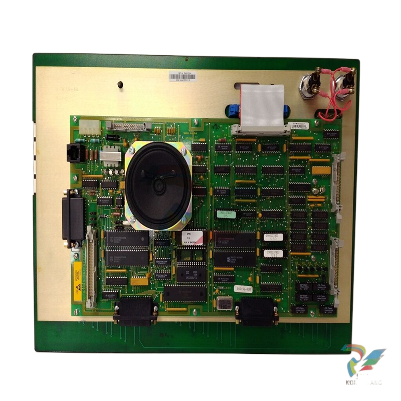
ABB SPFEC12 Analog Input Module
Overview
Product Definition and Function: The ABB SPFEC12 Analog Input Module is a module designed by ABB for the acquisition of analogue signals. It is mainly used in industrial automation control systems to convert analogue signals from external devices (e.g. sensors) into digital signals for processing and analysis by the control system. These analogue signals can be voltage or current signals, and represent a variety of physical quantities such as temperature, pressure, flow, level, etc.
Principle of operation
Signal Acquisition Process: The module has multiple analogue input channels which can be connected to various analogue signal sources, such as a 0 - 10V voltage signal from a temperature sensor for temperature values, or a 4 - 20mA current signal from a pressure sensor for pressure values. When an analogue signal is connected to the input channels of the module, the internal circuitry of the module first filters the signal to remove high-frequency noise and interfering components from the signal to ensure the quality of the collected signal.
Analogue - Digital Conversion (A/D Conversion): The filtered analogue signal is fed into the analogue - digital conversion circuit. This circuit samples the analogue signal at a certain sampling frequency and converts it to a digital signal. For example, the module may use a 12 - 16 bit A/D converter, which means that it can quantise the analogue signal into a number of different digital values, thus enabling highly accurate signal conversion. The converted digital signals are stored as binary code in the module's internal registers, waiting to be read by the control system.
Data transmission and processing: The module transmits the converted digital signals to the control system via an internal communication bus (e.g. backplane bus or industrial Ethernet). The control system can process these digital signals according to pre-programmed algorithms, e.g. converting the digital signals into actual physical values (by means of known relationships between the sensor signals and the physical quantities) and performing operations such as comparisons, calculations, control decisions, etc.
Performance Features
High-accuracy signal acquisition: High accuracy in analogue signal acquisition and conversion The A/D conversion accuracy can reach ±0.1% - ±0.5% full-scale accuracy, which makes it possible to accurately acquire and convert analogue signals. For example, for a voltage signal input with a full scale of 10V, the conversion error can be controlled within the range of ±10mV - ±50mV, which ensures accurate measurements of actual physical quantities.
Multi-Channel Input Function: Typically features multiple analogue input channels, the number of channels may vary from 4 - 16 depending on the module model. This multi-channel design allows the simultaneous acquisition of several different analogue signals, facilitating the monitoring of multiple physical quantities. For example, in an industrial process control system, analogue signals can be acquired simultaneously for several parameters such as temperature, pressure, liquid level, etc. in a reactor.
Signal filtering and anti-interference ability: with effective signal filtering function, it can filter out high-frequency interference signals in analogue signals, such as electromagnetic interference (EMI) and radio frequency interference (RFI). The filtered signal is purer and reduces measurement errors caused by interference signals. In addition, the modules are optimised in terms of hardware design and electromagnetic compatibility (EMC), enabling them to work stably in industrial environments with a certain level of electromagnetic interference.
Flexible input ranges and configurations: It supports a variety of analogue signal input ranges, for example, voltage signal input ranges can include - 10V - + 10V, 0 - 5V, 0 - 10V, etc., and current signal input ranges can include 4 - 20mA, 0 - 20mA, etc. Users can set the appropriate input ranges through software or hardware configuration (e.g. dip switches) according to the type and range of the actual connected sensor signals, which improves the versatility and flexibility of the module.
Technical Parameters
Input parameters
Number of analogue input channels: the number of channels is generally 4 - 16, the specific number of channels depends on the module model. Each channel can be configured and used independently.
Input signal type and range: Voltage and current signals are supported. Voltage signal input range may have various choices such as - 10V - + 10V, 0 - 5V, 0 - 10V, etc.; current signal input range commonly has 4 - 20mA, 0 - 20mA.
Input Impedance: For voltage signal input, the input impedance is high, usually between 100kΩ - 1MΩ, which can reduce the load effect on the signal source and ensure the accurate acquisition of voltage signal; for current signal input, the input impedance is low, usually between 50Ω - 200Ω to ensure that the current signal can flow into the module normally.
Conversion Parameters
A/D Conversion Resolution: 12-16 bit A/D converter is used, for example, 12 bit A/D converter can quantise the analogue signal into 4096 different digital values, while 16 bit A/D converter can quantise into 65536 digital values, which provides different levels of conversion accuracy.
A/D Conversion Accuracy: Conversion accuracy of ±0.1% - ±0.5% full-scale accuracy ensures high-precision signal conversion.
Sampling Frequency: The sampling frequency can be set according to the actual application requirements and may range from several thousand to several hundred thousand times per second. For example, a low sampling frequency, such as 1000 times per second, can be used to monitor a slow-changing temperature signal, while a high sampling frequency, such as 100000 times per second, is required to monitor a fast-changing vibration signal.
Communication parameters
Supported communication protocols: Communicate with the control system through the internal communication bus, support ABB-specific communication protocols, but also may be compatible with some industrial standard communication protocols, such as Modbus, Profibus, etc., to facilitate the integration with the control system of different manufacturers.
Communication rate: The communication rate varies depending on the communication protocol and connection method used. For example, when using industrial Ethernet communication, the communication rate can reach 10Mbps - 1000Mbps; when using Modbus protocol to communicate through serial port, the communication rate can be between 9600bps - 115200bps.
Physical Parameters
Dimensions: The external dimensions are generally designed according to the installation requirements of the system, the length may be between 10cm - 20cm, the width between 5cm - 10cm and the thickness between 3cm - 8cm, which is easy to be installed in the standard slot of the control cabinet or in the specific installation position of the equipment.
Weight: Light weight, usually between 100g - 500g, will not cause excessive burden on the overall weight and installation of the equipment.
Environmental parameters
Operating Temperature Range: Able to work in a wide range of temperatures, generally - 20 ℃ - + 60 ℃, can be adapted to different industrial site temperature conditions.
Humidity range: The relative humidity range is usually 10% - 90% (non-condensing), ensuring normal operation in different humidity environments.
| User name | Member Level | Quantity | Specification | Purchase Date |
|---|


- LTI Drives
- other
- ADLINK
- Beckhoff
- Shinkawa
- Other Brands
- AMAT
- Iba
- PEPPERL+FUCHS
- Aerotech
- WATLOW
- MAN
- ADVANCED
- Abaco
- YOKOGAWA
- KOLLMORGEN
- MEGGITT
- kong-sberg
- METSO
- Motorola
- NI
- OEMAX
- RELIANCE
- scanlab
- schneider
- uniop
- Vibro-Meter
- Honeywell
- Rolls-Royce
- MOOG
- GE
- B&R
- Woodward
- Yaskawa
- xYCOM
- Siemens
- Emerson
- HIMA
- Bently
- ZYGO
- FOXBORO
- OMACO
- PROSOFT
- ENTERASYS
- TRICONEX
- Parker
- Lenze
- KEBA
- Alstom
- CTI
- ABB
- A-B

-
 KUKA TITAN-2 Ultra Ground Overloading Six Axis Robot
 -
 Assembly instructions for KUKA KR SCARA-2 CS series robotic arm body
 -
 KUKA MA KR SCARA X Installation Guide
 -
 KUKA KR FORTEC-2 Ultra Heavy duty Ground Six Axis Robot Mechanical Assembly Manual
 -
 KUKA KR FORTEC-2 new generation heavy-duty ground six axis robot
 -
 KUKA Robots KR 1000 titan; KR 1000 L750 titan With F Variants Assembly Instructions
 -
 KUKA KR 600 FORTEC heavy-duty six axis ground mounted industrial robot
 -
 KUKA KR 500 MT FORTEC Heavy duty Six Axis Industrial Robot
 -
 KUKA KR 360 FORTEC Heavy duty Six Axis Industrial Robot
 -
 KUKA Sunrise Cabinet Med Medical Edition Robot Controller User Manual
 -
 KUKA Robots KR SCARA HO Assembly Instructions
 -
 KUKA Robots KR QUANTEC-2 PA Assembly Instructions
 -
 KUKA Robots KR QUANTEC-2 K and KR QUANTEC-2 P With K-F and P-C Variants Assembly Instructions
 -
 KUKA Robots KR QUANTEC-2 HO Assembly Instructions
 -
 KUKA Robots KR QUANTEC-2 HC Assembly Instructions
 -
 KUKA KR QUANTEC-2 series heavy-duty ground mounted six axis industrial robot
 -
 KUKA KR QUANTEC PA series heavy-duty palletizing robot
 -
 KUKA KR IONTEC-2 series six axis industrial robot
 -
 KUKA KR IONTEC ultra series six axis heavy-duty industrial robot
 -
 KUKA KR IONTEC HO Robot Assembly Manual
 -
 KUKA Robots KR CYBERTECH-3 HW Assembly Instructions
 -
 KUKA Robots KR CYBERTECH-3 Assembly Instructions
 -
 KUKA Robots KR CYBERTECH-2 arc Assembly Instructions
 -
 KUKA Robots KR CYBERTECH nano-2 Assembly Instructions
 -
 KUKA KR CYBERTECH CR HO (KR 20 R1810-HO) assembly instructions
 -
 KUKA Robots KR CYBERTECH With F variant Assembly Instructions
 -
 KUKA KR CYBERTECH CR (KR 20 R1810-CR) Clean Room (CR) Version 6-Axis Industrial Robot
 -
 KUKA KR AGILUS-3 ultra series small six axis serial robot
 -
 KUKA KR 300 R2700-2 C-F Cast Ceiling Mounted 6-Axis Heavy duty Industrial Robot
 -
 KUKA KR 20 R1820-2 E Six Axis Industrial Robot
 -
 Assembly instructions for KUKA KR AGILUS-3 small six axis robot
 -
 KUKA KR AGILUS-2 New Generation Small Six Axis Robot
 -
 KUKA KR 1000 1300 titan PA; KR 1000 L950 titan PA With F Variants Assembly Instructions
 -
 KUKA KR 700 PA/KR 700 PA Arctic Installation Guide
 -
 KUKA KR 18 R1450-3 PP six axis ground mounted industrial robot
 -
 KUKA 12 SCARA Series 4-axis SCARA Horizontal Joint Robot
 -
 KUKA KR 4 R600 Small Six Axis Industrial Robot
 -
 Installation Guide for KUKA KR 3 R540 Small 6-Axis Industrial Robot
 -
 KUKA LBR iiwa CR Clean 7-Axis Lightweight Collaborative Robot
 -
 KUKA KR AGILUS sixx series six axis industrial robot operation instructions
 -
 KUKA 4-axis heavy-duty SCARA horizontal multi joint robot KR 60 R1200 Z400 CS
 -
 KUKA KR 23 SCARA-2 CS SCARA Horizontal Multi Joint Robot
 -
 KUKA KR 20 SCARA CS Robot Assembly Instructions
 -
 KUKA KR 15 DELTA-2 Assembly Manual
 -
 KUKA KR 13 SCARA-2 CS Assembly Manual
 -
 KUKA KR 3 D1200 (Standard Delta Robot) Assembly Instructions
 -
 KUKA KR 3 D1200 HM Assembly Manual
 -
 KUKA LBR Med 7 R800, LBR Med 14 R820 Medical Edition Robot
 -
 KUKA Robots LBR iiwa 7 R800, LBR iiwa 14 R820 Operating instructions
 -
 KUKA LBR iiwa CR (Clean Room Version Robot) Operating Instructions
 -
 Lauer PCStopline series text operation panel
 -
 KUKA LBR iisy (MA_LBR_iisy V5) assembly manual
 -
 KUKA LBR iisy 3 R760 Assembly Manual
 -
 KUKA LBR iico Collaborative Robot Assembly Manual
 -
 Lauer LCAstarline (LCA300/LCA320/LCA325) Text Display Screen
 -
 Lauer PCS950/PCS950c/PCS950e operation console
 -
 Lauer EPC Series Industrial Embedded Human Computer Integrated PC User Guide
 -
 Bonfiglioli Precision Planetary Gearbox TIR-STD ENG R07
 -
 Bonfiglioli ACT/ACU Cold Plate Inverter Installation Instructions
 -
 Bonfiglioli EM-RES-02 Expansion Module
 -
 Bonfiglioli EM-RES-01 Expansion Module
 -
 Bonfiglioli EM-IO-04 Expansion Module
 -
 Bonfiglioli EM-IO-03 Expansion Module
 -
 Bonfiglioli EM-IO-02 Expansion Module
 -
 Bonfiglioli Vectron EM-IO-01 Expansion Module
 -
 Bonfiglioli F series gearbox
 -
 Installation, operation, maintenance, and spare parts of Bonfiglioli HF series reducers
 -
 Installation, Operation, and Maintenance of Bonfiglioli 300-300M Series ATEX Reducer
 -
 Bonfiglioli R3 series planetary gearbox
 -
 Bonfiglioli C series inline helical gear explosion-proof reducer
 -
 Bonfiglioli EM-ENC-05 Expansion Module
 -
 Bonfiglioli EM-ENC-04 Expansion Module
 -
 Bonfiglioli EM-ENC-03 Expansion Module
 -
 Bonfiglioli EM-ENC-02 Expansion Module
 -
 Bonfiglioli CM-CAN CANopen communication module
 -
 Bonfiglioli EM-SYS System Bus Expansion Module
 -
 Bonfiglioli CM-PDP Profibus DP Communication Module
 -
 Bonfiglioli CM-232/CM-485/CM-485T Modbus Communication Manual
 -
 Bonfiglioli BMS series precision planetary servo reduction motor
 -
 Bonfiglioli ACTION series ACT210 (230V), ACT410 (400V) frequency converter operation manual
 -
 Bonfiglioli ACT series frequency converter
 -
 Bonfiglioli HDP/HDO series gear unit IOM installation, operation and maintenance instructions
 -
 Installation, operation, and maintenance of Bonfiglioli 300-300M series reducers
 -
 Bonfiglioli 300M Modular planetary gearboxe
 -
 Bonfiglioli 3/H series heavy-duty modular gearbox
 -
 Bonfiglioli KRG-KCG-KSD hydraulic coupling
 -
 Bonfiglioli Vectron BTD-BCR servo motor
 -
 Bonfiglioli BTD-BCR synchronous servo motor
 -
 Bonfiglioli VF-W series ATEX explosion-proof worm gear reducer
 -
 Bonfiglioli EM-ENC-03 Expansion Module
 -
 Installation, operation, maintenance, and spare parts instructions for Bonfiglioli EVOX-CP series helical gear reducers (including ATEX explosion-proof models)
 -
 Installation, operation, and maintenance IOM instructions for Bonfiglioli C/A/F/S series gear reducers (including ATEX explosion-proof versions)
 -
 Bonfiglioli BX-BE-BN-MX-ME-BXN-MNN Motor Installation, Operation and Maintenance Manual
 -
 Bonfiglioli VF-W IE2-IE3 Worm Gear Reduction Motor: Complete Selection, Verification, and On site Implementation Technical Guide
 -
 Bonfiglioli VF-W series ATEX worm gear reducer
 -
 Bonfiglioli RAN series bevel gear angle reducer
 -
 Bonfiglioli Industry&Automation Business Unit Integrated Products
 -
 Bonfiglioli EVOX platform CP coaxial helical gear reduction motor
 -
 Bonfiglioli C-A-F-S Series IE2-IE3-IE4 three series reducers
 -
 Complete selection, calibration, and common selection of Bonfiglioli C-A-F industrial gear units
 -
 Bonfiglioli C series explosion-proof helical gear reducer
 -
 Bonfiglioli BN-BE-BX-BY series three-phase asynchronous motor
 -
 Bonfiglioli BMD series permanent magnet AC synchronous servo motor
 -
 Bonfiglioli A-series spiral bevel gear right angle servo reduction motor
 -
 Installation, Operation, and Maintenance Instructions for Bonfiglioli AS Series Reducer
 -
 Bonfiglioli Active series high-end frequency converter
 -
 Bonfiglioli EM-IO-04 Expansion Module
 -
 Bonfiglioli EM-ENC-02 Expansion Module
 -
 Bonfiglioli A-series spiral bevel gear reducer sample
 -
 Bonfiglioli Industrial Transmission Products
 -
 Bonfiglioli RAN series gearbox
 -
 Bonfiglioli Active 401/201 frequency converter
 -
 Alcatel Lucent OmniAccess Stellar AP1301 Indoor Wi Fi 6 (802.11ax) Wireless Access Point
 -
 Alcatel Lucent Enterprise (ALE) Mobile Handheld Terminal Electronics
 -
 Alcatel Lucent MDR-8000 Digital Microwave Radio
 -
 Alcatel 1660 SM Release 5 Optical Multi Service Node
 -
 Alcatel Lucent OmniSwitch 6850 Stackable LAN Switch
 -
 Alcatel Lucent 7750 Service Router (SR) series business router
 -
 Alcatel 1600 series SDH optical transmission equipment
 -
 Alcatel Lucent 9500 MPR Release 3 ANSI Microwave Packet Radio Equipment
 -
 Alcatel Lucent 7450 operator Ethernet service switch
 -
 Alcatel Advanced REFLEXES (OmniPCX 4400) telephone
 -
 Alcatel Lucent OmniSwitch 6850E Stacked Gigabit Switch
 -
 Alcatel Lucent OmniSwitch 6450 Stackable Gigabit Ethernet Switch Series
 -
 Lucent Stinger ATM DSL Access Concentrator
 -
 Alcatel Lucent 1660SM OMSN (Optical Multi Service Node) series next-generation SDH equipment
 -
 ALCATEL-LUCENT 9500 MICROWAVE PACKET RADIO
 -
 Atlas Copco MT Focus 6000 Tightening Controller

K-JIANG

Add: Jimei North Road, Jimei District, Xiamen, Fujian, China
Tell:+86-15305925923