

K-WANG


- Telephone:+86-15305925923
- contacts:Mr.Wang
- Email:wang@kongjiangauto.com
THE V7768/V7769 IS DESIGNED TO MEET THE EUROPEAN UNION (EU) RESTRICTIONS OF HAZARDOUS SUBSTANCE (ROHS) DIRECTIVE (2002/95/EC) CURRENT REVISION.
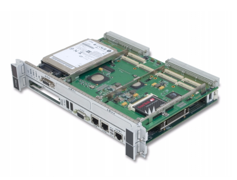
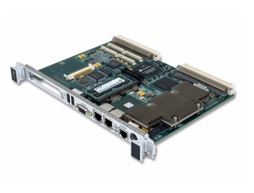
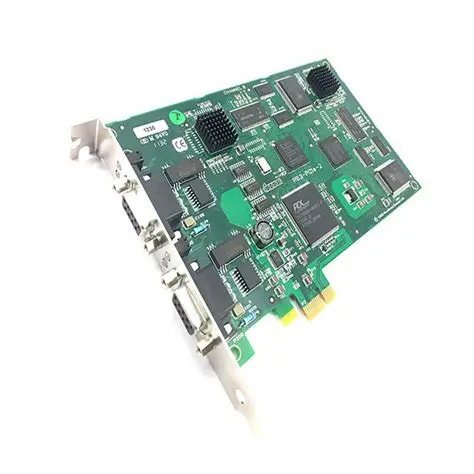
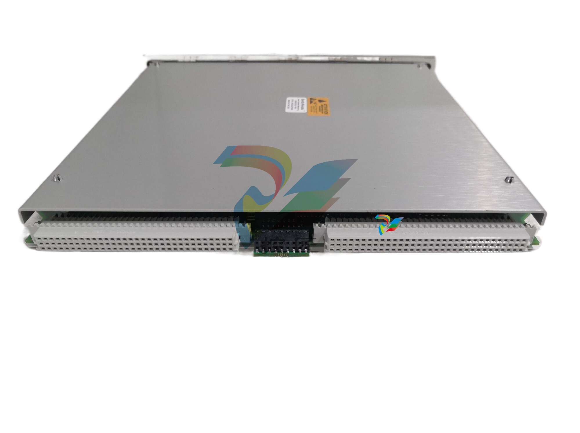
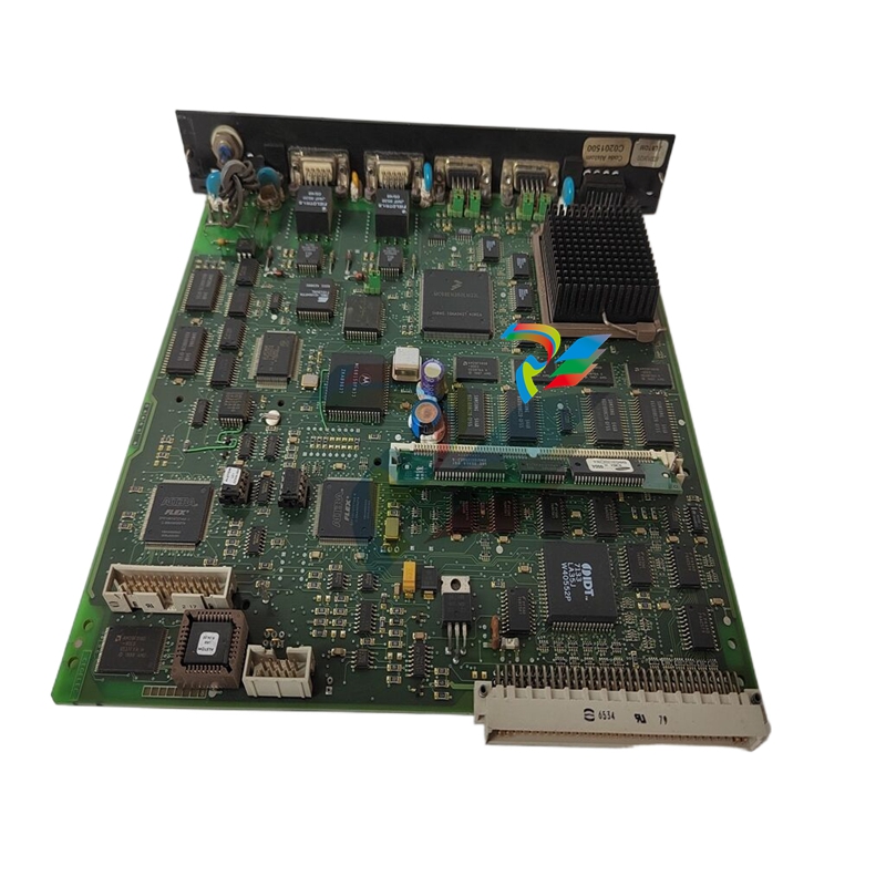
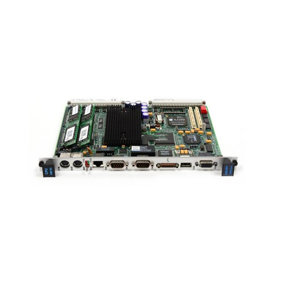
Motorola V7768 Duo Processor VME Single Board Computer
GE’s V7768/V7769* are single board computers (SBCs) in a dual-slot, passively
cooled, VME Eurocard form factor.
The V7768* is a full featured Intel® CoreTM 2 Duo or Celeron® M-based SBC, and
the V7769* is a full featured Intel Core 2 Duo-based SBC. The V7768/V7769 utilize
the advanced technology of Intel’s 945GM chipset and the ICH7-M I/O Controller
Hub. The 945GM chipset runs on a 533 MHz front-side bus with the Celeron M
processor and a 667 MHz front-side bus with the Core 2 Duo processor.
The V7768/V7769 are compliant with the VMEbus Specification VITA 1-1994 and
feature a transparent PCI-to-VME bridge, allowing your board to function as a
system controller or peripheral CPU in multi-CPU systems.
The V7768 is a single-slot board, and the V7769 is a dual-slot board. The V7769
has the same functionality as the V7768 and also connects to the ACC-0623*
(which will be referred to as the mezzanine board throughout this manual),
making it a dual-slot board. Because the functionality is so similar, this manual
will refer to both boards (V7768/V7769) throughout unless the material is
referring to the V7768 or V7769 only.
Desktop Features of the V7768/V7769
• Up to 2.0 GByte DDR2 SDRAM (One SODIMM)
• SVGA port (front I/O)
• Dual Gigabit Ethernet (GbE) (front I/O)
• One RS232/422 COM port (front I/O)
• One RS232/422 COM support (rear I/O)
• Two USB 2.0 ports (front I/O)
• Four USB 2.0 support (rear I/O)
• Supports two SATA connections (rear I/O)
• One 2.5-in. SATA hard drive (optional for V7769 only)
• Dual SAS connector (front I/O on V7769 only)
• Real-Time clock/calendar
• Front panel reset switch
• PS/2 Keyboard/Mouse connection (front I/O)
• Onboard parallel connector
The 945GM chipset allows the V7768/V7769 to be capable of executing many of
today’s desktop operating systems such as Microsoft®’s Windows® XP, Windows
Vista®, Linux® 2.6.x, and VxWorks® 6.x. The standard desktop features of the
V7768/V7769 are described in Chapter 2: Standard Features of this manual.
Embedded Features of the V7768/V7769
• Remote booting out the front panel only
• Up to 8 GByte of bootable CompactFlash (optional)
• PCI-X capable PMC site with VITA 35 P2 I/O (factory populated on V7768
and main board of V7769)
• VITA 1-1994 with byte swap
• 32 KByte NVRAM
• Software-selectable Watchdog Timer with reset
• PMC expansion site Chapter 3: Embedded PC/RTOS Features
The embedded features of the V7768/V7769 are described in Chapter 3 of this
manual.
The V7768/V7769 are suitable for use in a variety of applications, such as:
telecommunications, simulation, instrumentation, industrial control, process
control and monitoring, factory automation, automated test systems, data
acquisition systems and anywhere that the highest performance processing
power for VME in a single or dual slot is desired.
Intel 945GM Chipset
The V7768/V7769 incorporate the latest Intel chipset technology, the 945GM. The
Intel 945GM chipset is an optimized integrated graphics solution with up to a
667 MHz system bus. The chipset has a low power design, advanced power
management, supporting up to 2 GByte of DDR2 system memory. The 945GM is a
Memory Controller Hub (MCH) component, providing the processor interface,
system memory interface (DDR2 SDRAM) and SVGA port.
Key features for the 945GM:
• 533 MHz Processor system bus controller for the Celeron M
• 667 MHz Processor system bus controller for the Intel Core 2 Duo
• Up to 2 GByte DDR2 Memory via SODIMM
• High-speed DMI architecture interface for communication with the ICH7-M
(I/O controller)
The 945GM supports the Intel ICH7-M I/O controller hub. The ICH7-M supports
most of the high speed I/O interfaces of the V7768/V7769.
Key features for the ICH7-M:
• USB 2.0
• SATA
• IDE (Primary only)
• PCI
• PCI Express (PCIe)
Safety Summary
The following general safety precautions must be observed during all phases of
the operation, service and repair of this product. Failure to comply with these
precautions or with specific warnings elsewhere in this manual violates safety
standards of design, manufacture and intended use of this product.
GE assumes no liability for the customer's failure to comply with these
requirements.
Ground the
System
To minimize shock hazard, the chassis and system cabinet must be connected to
an electrical ground. A three-conductor AC power cable should be used. The
power cable must either be plugged into an approved three-contact electrical
outlet or used with a three-contact to two-contact adapter with the grounding
wire (green) firmly connected to an electrical ground (safety ground) at the power
outlet.
Do Not Operate in
an Explosive
Atmosphere
Do not operate the system in the presence of flammable gases or fumes. Operation
of any electrical system in such an environment constitutes a definite safety
hazard.
Keep Away from
Live Circuits
Operating personnel must not remove product covers. Component replacement
and internal adjustments must be made by qualified maintenance personnel. Do
not replace components with power cable connected. Under certain conditions,
dangerous voltages may exist even with the power cable removed. To avoid
injuries, always disconnect power and discharge circuits before touching them.
Do Not Service or
Adjust Alone
Do not attempt internal service or adjustment unless another person capable of
rendering first aid and resuscitation is present.
Do Not Substitute
Parts or Modify
System
Because of the danger of introducing additional hazards, do not install substitute
parts or perform any unauthorized modification to the product. Return the
product to GE for service and repair to ensure that safety features are maintained.
Dangerous
Procedure
Warnings
Warnings, such as the example below, precede only potentially dange
| User name | Member Level | Quantity | Specification | Purchase Date |
|---|


-
 ABB DI810 digital input module
 -
 ABB Harmony Sequence of Events (SOE) system
 -
 ABB Tension Electronics PFEA111/112
 -
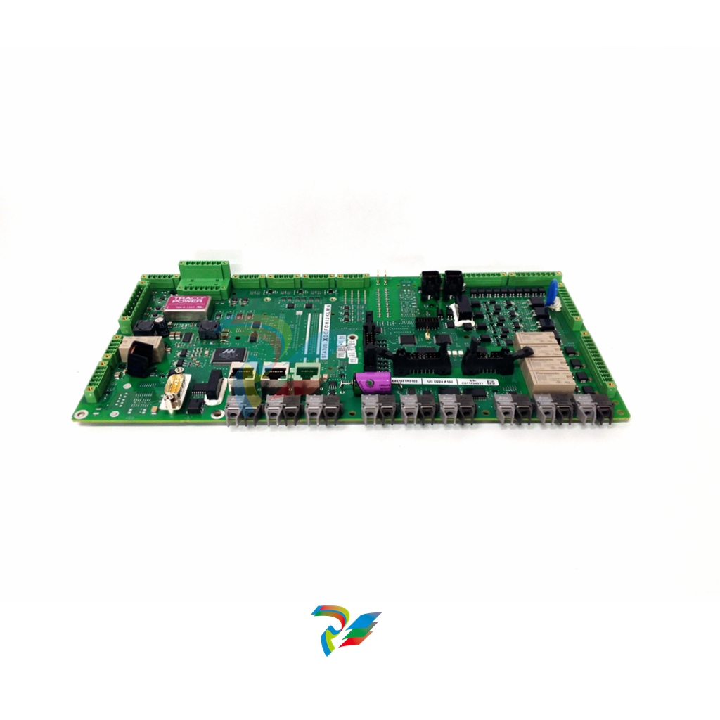 ABB AI801 Analog Input Module
 -
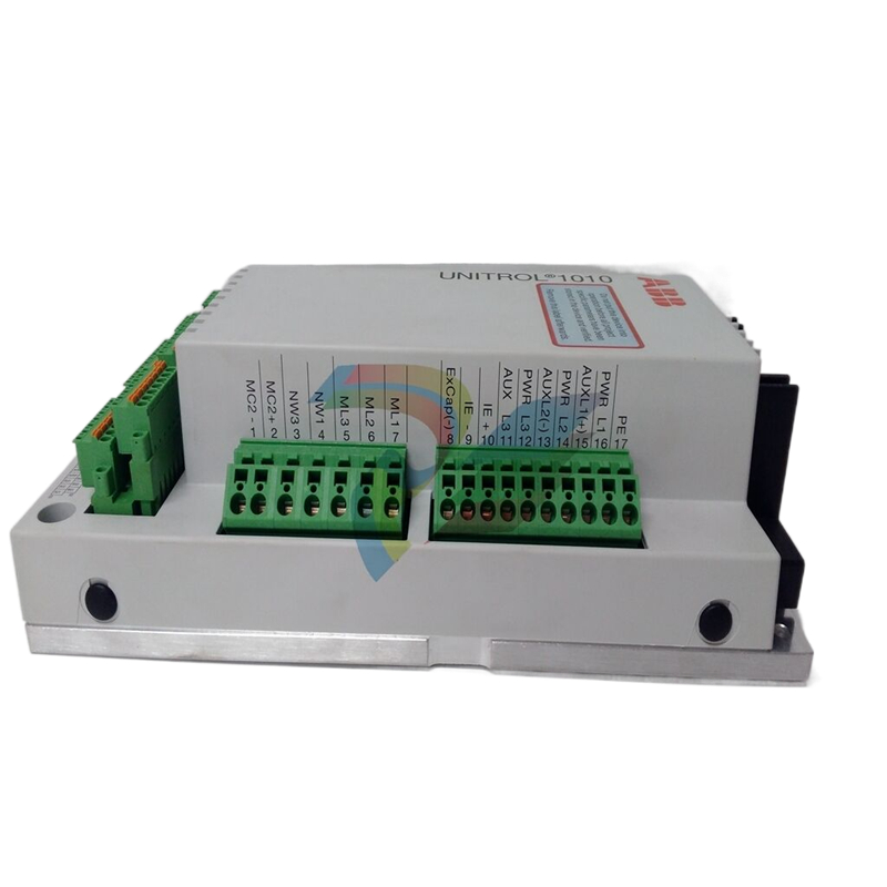 ABB AF C094 AE02 ARCnet Control Board
 -
 ABB TP830-1 PLC module
 -
 ABB CP430 Human Machine Interface (HMI) Installation and Operation
 -
 ABB 81EU01-E/R3210 Analog Signal Input Module
 -
 ABB Panel 800- PP836 5.1 Hardware and Installation
 -
 ABB PM866AK01 Controller
 -
 ABB TK850V007 CEX Bus expansion cable Installation and configuration method
 -
 ABB AO801 Analog Output Module
 -
 ABB CI855 communication interface
 -
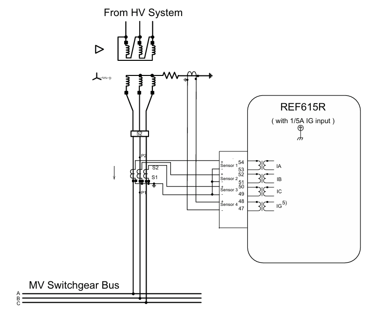 ABB REF615R feeder protection and control
 -
 ABB EL3020 Model EasyLine Continuous Gas Analyzers
 -
 MOLEX SST-PB3-VME-1 and SST-PB3-VME-2 Hardware Reference Guide
 -
 Eaton XVH300 MICRO PANEL
 -
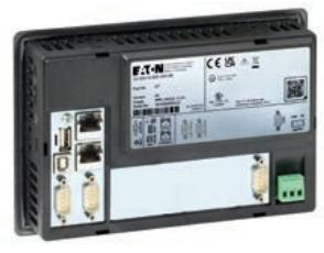 Eaton XV-303/XV-313 multi touch display
 -
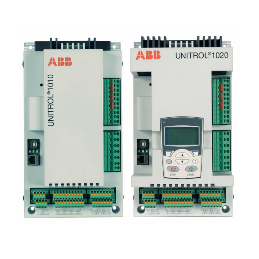 ABB Panel 800 Version 6 Operator Panel
 -
 ABB 1SVR011718R2500 Analog Signal Converter
 -
 ABB BC810K02 CEX Bus Interconnection Unit Kit
 -
 ABB RELION ® 615 series REU615 voltage protection and control relay
 -
 ABB Symphony Harmony/INFI 90 DCS Remote I/O Module Upgrade Kit
 -
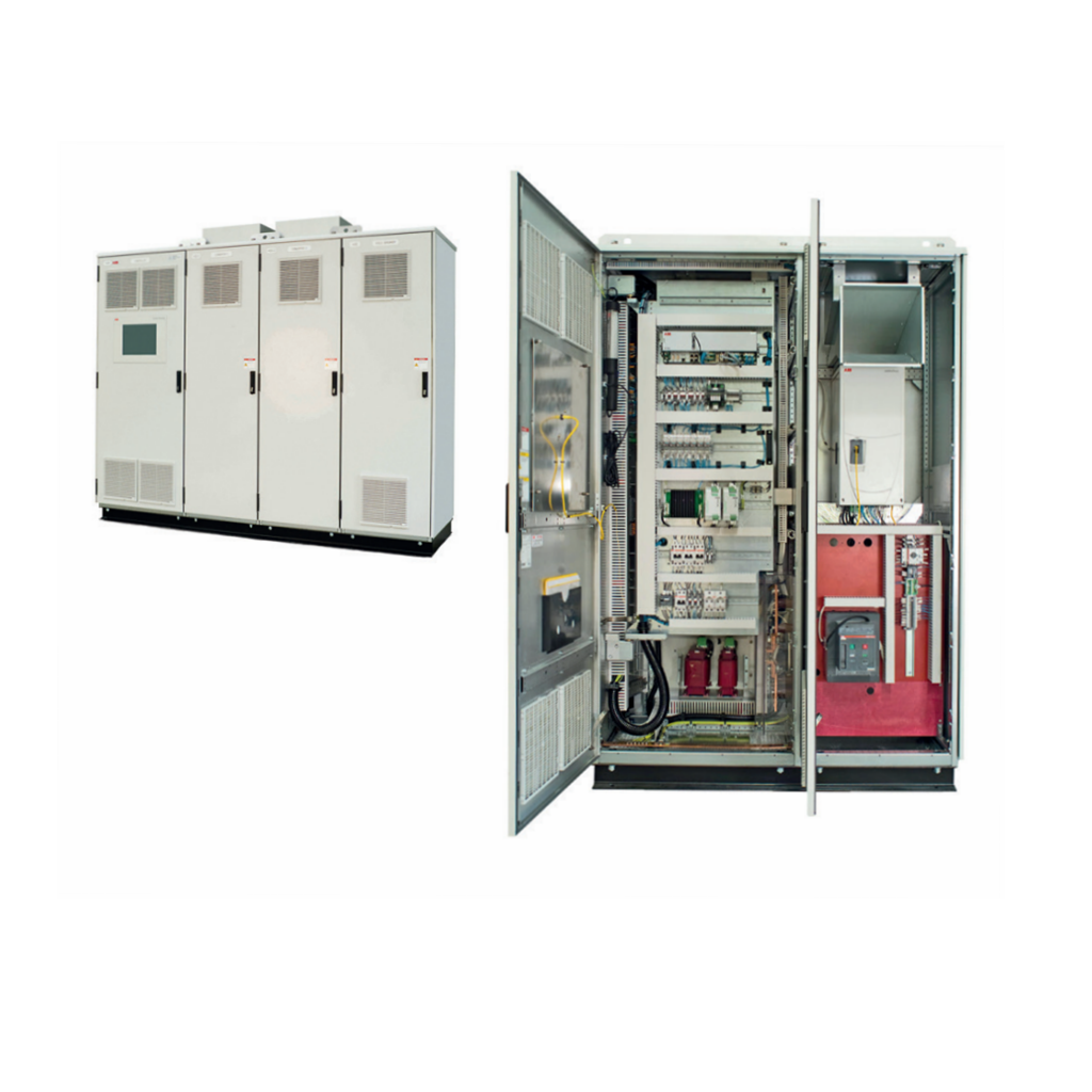 ABB REM610C55HCNN02 motor protection relay
 -
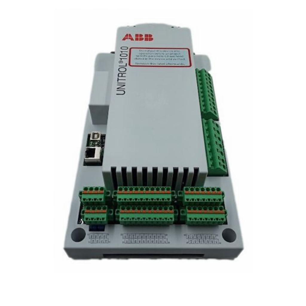 ABB TU810V1 Compact Terminal Unit
 -
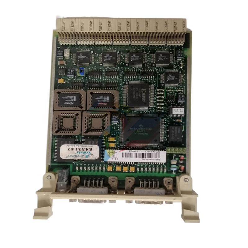 ABB REF 541, REF 543, and REF 545 feeder terminals
 -
ABB UNITOL 1000 series automatic voltage regulator
-
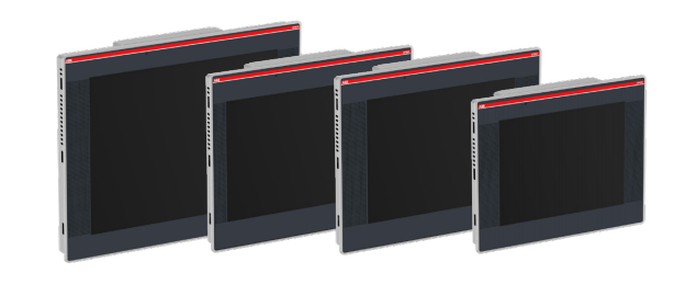 ABB PCD235C101 3BHE057901R0101 AC800pec Excitation High Performance Control System
 -
ABB GFD233 3BHE022294R0102 Redundant System Control Module
-
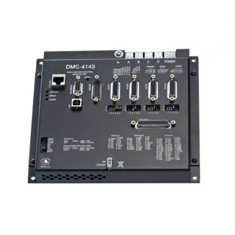 Galil DMC-40x0 series motion controller
 -
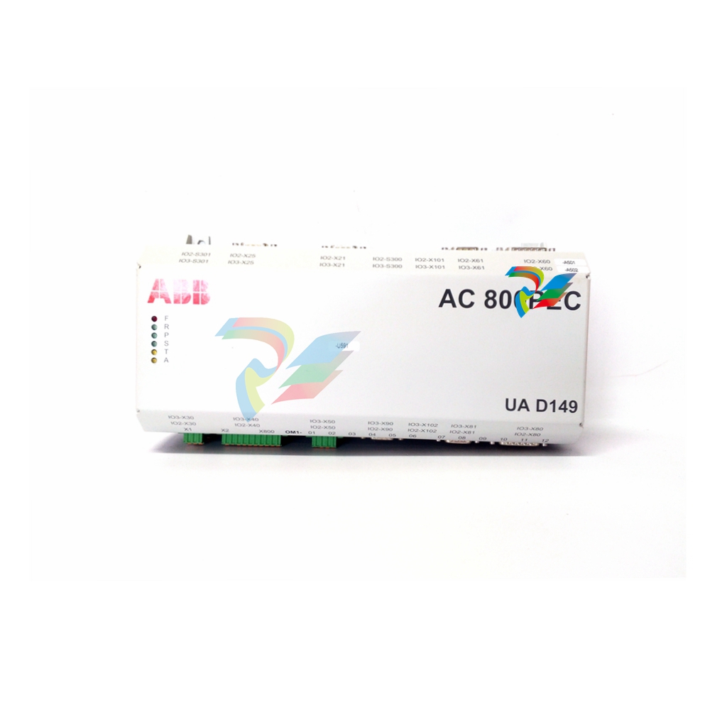 ABB AO2040-CU Ex Central Unit
 -
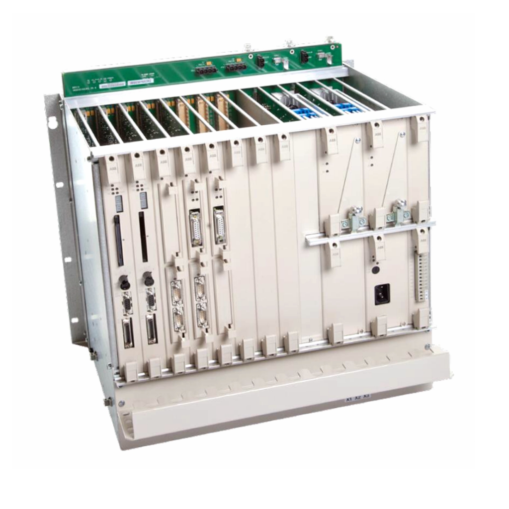 ABB REF615 feeder protection relay
 -
 ABB INSUMMCU2 MCU2A02V24 motor control unit
 -
 ABB REF 542plus multifunctional protection and switchgear control unit
 -
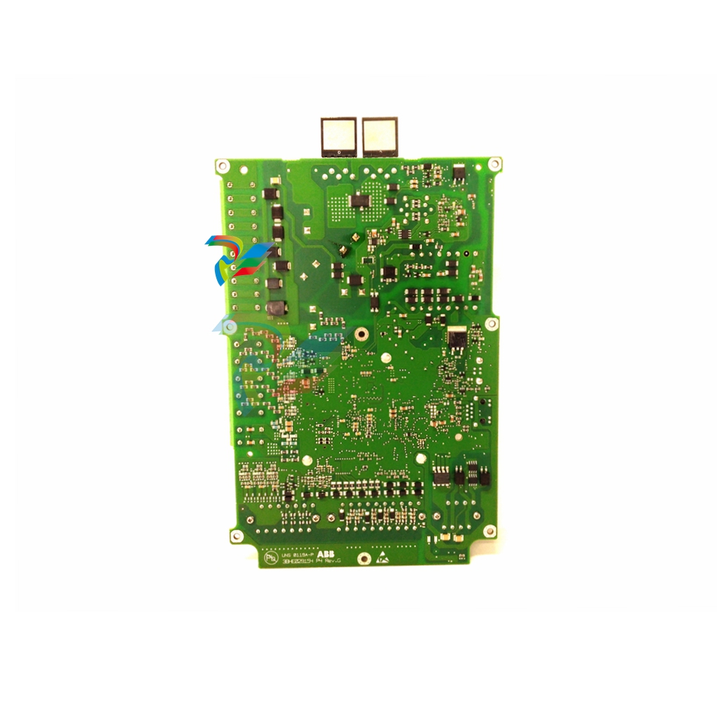 ABB PP886 Compact Product Suite hardware selector
 -
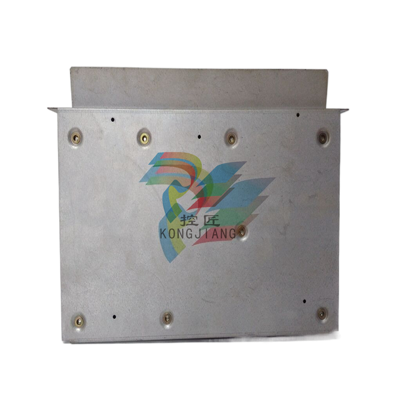 ABB AC500 V3 PLC Enhanced connectivity and performance
 -
ABB SYNCHROTACT ® 5 Synchronous and Parallel Devices
-
 ABB SUE 3000 high-speed switching device
 -
 ABB REF542plus multifunctional protection and switchgear control unit
 -
 ABB Relion ® 615 series REF615 feeder protection and control device
 -
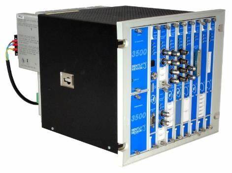
 Bentley 3500/45 Position Monitor
 -
Bentley 3500/42 Proximitors ®/ Earthquake monitoring module
-
 ABB molded case circuit breaker
 -
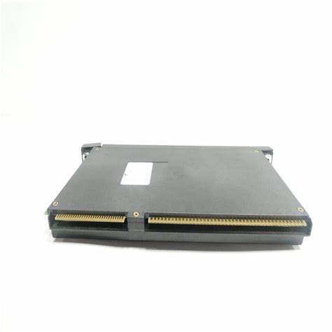
 ABB MVME162 Embedded Controller
 -
 ABB TU810V1 System 800xA hardware selector
 -
 ABB SPAJ 140 C overcurrent and ground fault relay
 -
ABB AC 800PEC High Performance Control System
-
ABB REF601 and REJ601 relays
-
 ALSTOM RPH3/PS125b Controlled Switching Device,CT1VT220/TCR
 -
 ABB V-Contact VSC Medium voltage vacuum contactors
 -
ABB 3BHE004385R0001 UNS 0884a, V1:Current Sensor 2000A
-
ABB UAD206A101 Programmable Logic Controller
-
 ABB ACS800-04/U4 driver module
 -
 ABB UAD149A0011 3BHE014135R0011 Controller Module
 -
 ABB BSM series AC servo motor
 -
 ALSTOM DFI-150-0003- Limelight Diagnostic Board
 -
 ABB GCC960C102 motor driver
 -
 ABB INDUSTRIALDRIVES UCU-22, UCU-23 andUCU-24control units
 -
ABB XDD501A101 Bus Terminal Module
-
 ABB S800 I/O DTM 5.3 module
 -
 ALSTOM N897164611M High Performance Control Module
 -
 ALSTOM N897164610L Pulse Output Module
 -
 ALSTOM N70032702L High Performance Control Module
 -
 ALSTOM MVAJ1L1GB0771B Auxiliary Transmission Relay
 -
 GE 239 MOTOR PROTECTION RELAY
 -
 ALSTOM ADVANCED MICRO CONTROLLER 2
 -
 Honeywell HC900 Process and Safety Controller
 -
ABB ControlMaster CM10 Universal Process Controller
-
ABB dual power conversion switch
-
 ABB RET 541/543/545 Transformer Terminal Device
 -
 ABB Relion ® RET620 Transformer Protection and Control Device
 -
 ABB Relion ® REU615 Voltage Protection and Control Device
 -
 ABB Relion ® REU615 Voltage Protection and Control Device
 -
 ABB REX615 Protection and Control Relay Products
 -
ABB PGC2000 series E2 process gas chromatograph
-
 ABB PROCOLOR P 88QT03 bus coupling module
 -
 Honeywell WEB-8000 Controller
 -
 ABB Protection Relay REX 521
 -
 ABB 5SGY3545L0020 Controller Module
 -
ABB 5SGY3545L0017 module tension controller
-
ABB 5SGY3545L003 IGCT control module
-
ABB SNAT609TAI 5761789-6H Industrial I/O Interface Card
-
ABB SNAT602TAC circuit board
-
ABB SNAT603 CNT Control Board
-
ABB SNAT634PAC pulse amplifier module
-
 ABB RK682011-BA RL0B 100 standard unit module
 -
 ABB PP846A 3BSE042238R2 Industrial Control Panel
 -
 ABB ZMU-02 inverter memory card
 -
ABB 3BHE014135R0011 UAD149A0011 DCS POSITIONING CONTROL MODULE
-
ABB 3BHE014135R0011 UAD149 A00-0-11 I/O module
-
 ABB MEASUREMENT & ANALYTICS Web Tension Systems with Tension Electronics PFEA113
 -
 ABB GDD471A001 2UBA0022R0001 motor control module
 -
ABB UCD224A103 high-performance control module
-
 ABB PDD205A0121 control module
 -
ABB PDD205A1121 3BHE02535R1211 processor module
-
 ABB DSDX453 Digital Input/Output Module
 -
ABB DSPC454 controller module
-
 Woodward ESDR4 Current Differential Protection Relay
 -
 Siemens SIJECT CI16iP StepB 6AТ1131-6DF21-0AB0 Compact Control
 -
 EtherNet/IP™ to Remote I/O or DH+ Gateway AN-X2-AB-DHRIO
 -
ABB 81EU01-E/R3210 Analog Signal Input Module
-
 ABB TK457V050 Industrial Temperature Controller
 -
 ABB DSRF197K01 Control Module
 -
 ABB TK802F SD802F/SD812F power cord
 -
ABB 3BHE03930R0101 I/O module
-
ABB 3BHB0040277R0101 GVC700AE01 thyristor module
-
 ABB 3BHB003154R0101 5SXE05-0156 IGCT module
 -
 RELIANCE INSPECTOR VCIB-06 Advanced Industrial Visual Display
 -
ABB AO2000-LS25 Laser analyzer
-
 HIMA F8650X Central module
 -
ABB PM864AK01 Classic System 800xA hardware selector
-
ABB 3BSE048845R1 CI868K01 IEC 61850 Interface
-
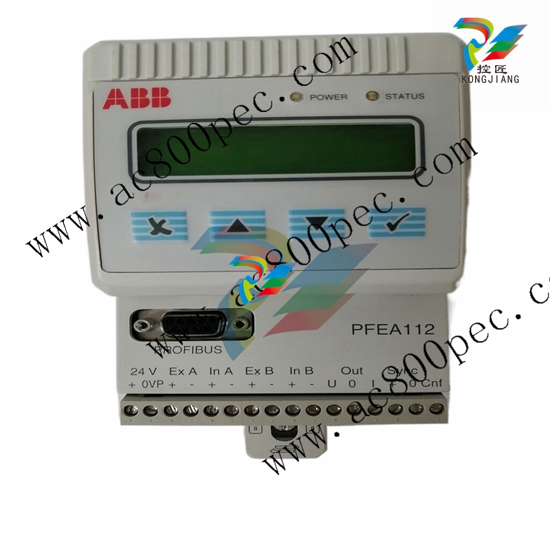 ABB 5SHY35L4520 Asymmetric Integrated Gate Converter Thyristor
 -
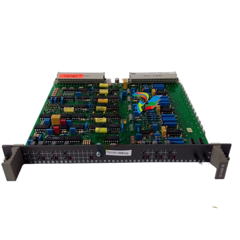 ABB UNS0119A-P V101 3BHE029153R0101 processor module
 -
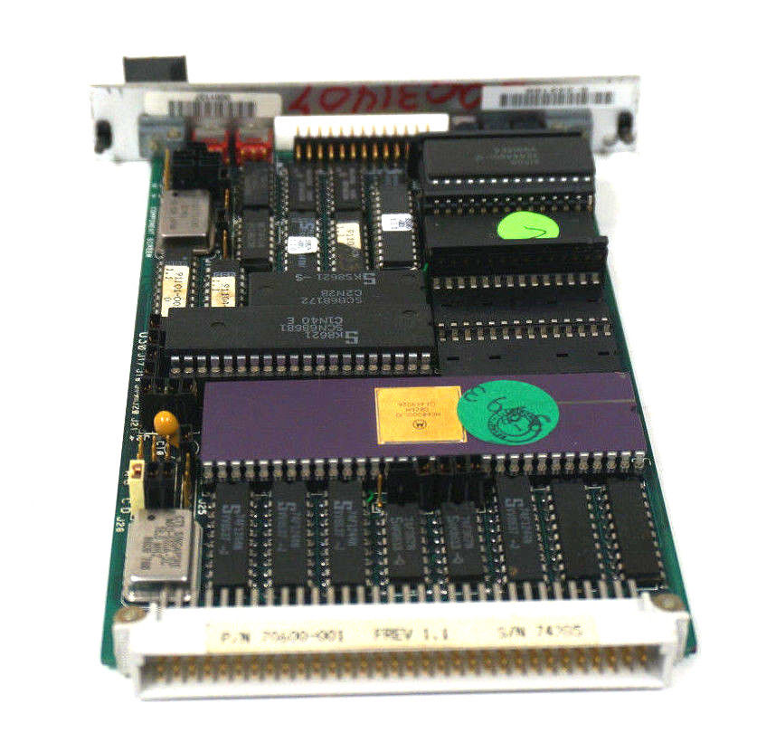 Xycom 99212A-001 PC board
 -
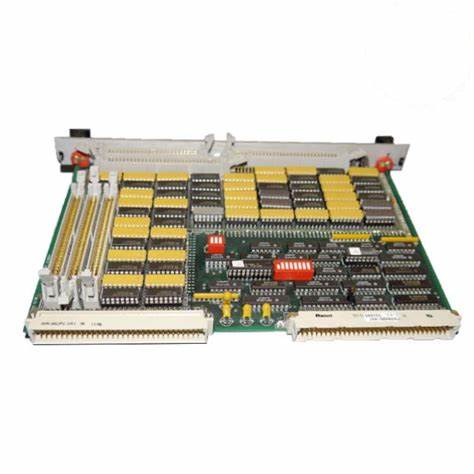
 Xycom 144365-001 motherboard
 -
 XYCOM 70400-001 T3065-4 XVME-400 Board
 -
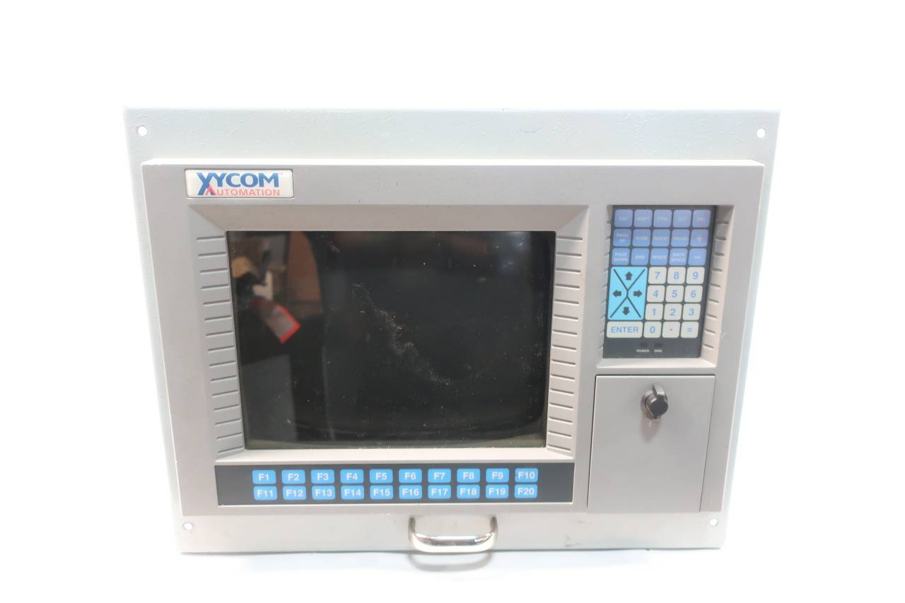 Xycom Automation # 9450-2480016010000 Interface Monitor Model
 -
 XYCOM 70560-001 AIN XVME-560, VMEbus module card, PCB board
 -
 Xycom XVME-491 VMEbus 71491A PN70491-001
 -
 Xycom 99157-001 Circuit Board
 -
 Xycom 1341 egemin PM-070016 computer P/N 701301-01 TF-AEC-6910-C13
 -
 Xycom 8430 Industrial Controller Options 71338 115/230V P/N 8430-078122A002110
 -
 Xycom XVME-203 VME Digital Counter I/O Module Board PLC 70203-001
 -
ABB UNS0119A-P V101 Controller Module
-
ABB GCC960C103 3BHE033067R0103 Controller Module
-
ABB GVC736CE101 High Performance AC Inverter
-
 ABB PCD244A101 Terminal Card Module

