
K-WANG


- Telephone:+86-15305925923
- contacts:Mr.Wang
- Email:wang@kongjiangauto.com
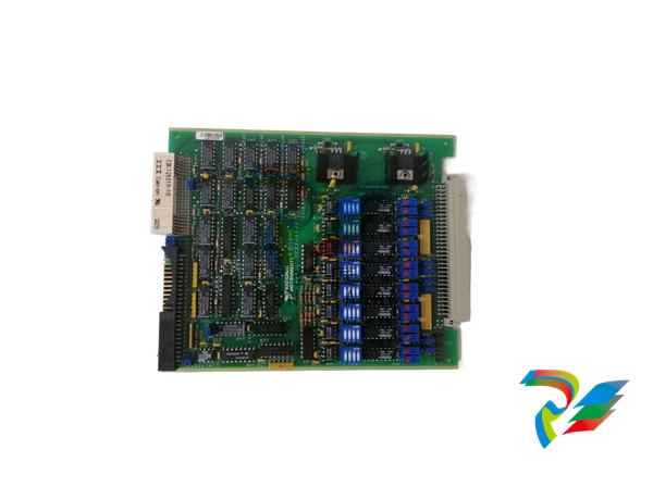
NI CFP-AI-100 Analog Input Modules
NI CFP-AI-100 Analog Input Modules
DESCRIPTION
These operating instructions describe how to install and use the FP-AI-100 and cFP-AI-100 analog input modules (referred to inclusively as the [c]FP-AI-100). For information about configuring and accessing the [c]FP-AI-100 over a network, refer to the user manual for the FieldPoint network module you are using.
Features
The [c]FP-AI-100 is a FieldPoint analog input module with the following features:
• Eight analog voltage or current input channels
• 11 input ranges: 0–1 V, 0–5 V, 0–15 V, 0–30 V, ±1 V, ±5 V, ±15 V, ±30 V, 0–20 mA, 4–20 mA, and ±20 mA
• 12-bit resolution
• 250 Vrms CAT II continuous channel-to-ground isolation, verified by 2,300 Vrms,1 minute dielectric withstand test
• –40 to 70 °C operation • Hot swappable
Installing the FP-AI-100
The FP-AI-100 mounts on a FieldPoint terminal base (FP-TB-x), which provides operating power to the module. Installing the FP-AI-100 onto a powered terminal base does not disrupt the operation of the FieldPoint bank.
To install the FP-AI-100, refer to Figure 1 and complete the following steps:
1. Slide the terminal base key to either position X (used for any module) or position 1 (used for the FP-AI-100).
2. Align the FP-AI-100 alignment slots with the guide rails on the terminal base.
3. Press firmly to seat the FP-AI-100 on the terminal base. When the FP-AI-100 is firmly seated, the latch on the terminal base locks it into place.
Installing the cFP-AI-100
The cFP-AI-100 mounts on a Compact FieldPoint backplane (cFP-BP-x), which provides operating power to the module. Installing the cFP-AI-100 onto a powered backplane does not disrupt the operation of the FieldPoint bank.
To install the cFP-AI-100, refer to Figure 2 and complete the following steps:
1. Align the captive screws on the cFP-AI-100 with the holes on the backplane. The alignment keys on the cFP-AI-100 prevent backward insertion.
2. Press firmly to seat the cFP-AI-100 on the backplane.
3. Using a number 2 Phillips screwdriver with a shank of at least 64 mm (2.5 in.) length, tighten the captive screws to 1.1 N ⋅ m (10 lb ⋅ in.) of torque. The nylon coating on the screws prevents them from loosening.
Input Ranges
To prevent inaccurate readings, choose an input range such that the signal you are measuring does not exceed either end of the range. If a channel is not in use, short the positive input to ground and configure the channel for a bipolar input range. Small fluctuations in floating input signals can cause the red Out of Range status LED on the module to light if the channel is configured for a unipolar range. Similarly, if a channel is configured for 4–25 mA input and the input current is 0 mA, the channel is always out of range.
Overranging
The [c]FP-AI-100 has an overranging feature that measures a little beyond the nominal values of each range. For example, the actual measurement limit of the ±5 V range is ±6.0 V. The overranging feature allows the [c]FP-AI-100 to compensate for field devices with span errors of up to +20% of full scale. Also, with the overranging feature, a noisy signal near full scale does not create rectification errors.
Specifications
Input Characteristics
Number of channels..........................8
ADC resolution.................................12 bits
Type of ADC.....................................Successive approximation
Update rate (all channels) .................360 Hz (2.8 ms)
| User name | Member Level | Quantity | Specification | Purchase Date |
|---|


- other
- LTI Drives
- ADLINK
- Beckhoff
- Other Brands
- AMAT
- Iba
- PEPPERL+FUCHS
- Aerotech
- WATLOW
- MAN
- ADVANCED
- Abaco
- YOKOGAWA
- KOLLMORGEN
- MEGGITT
- kong-sberg
- METSO
- Motorola
- NI
- OEMAX
- RELIANCE
- scanlab
- schneider
- uniop
- Vibro-Meter
- Honeywell
- Rolls-Royce
- MOOG
- GE
- B&R
- Woodward
- Yaskawa
- xYCOM
- Siemens
- Emerson
- HIMA
- Bently
- ZYGO
- FOXBORO
- OMACO
- PROSOFT
- ENTERASYS
- TRICONEX
- Parker
- Lenze
- KEBA
- Alstom
- CTI
- ABB
- A-B

-
 ADLINK PCI-9112/cPCI-9112 multifunctional acquisition card
 -
 ADLINK PCI-8102 Two Axis Pulse Motion Control Card
 -
 ADLINK PCI-9812/PCI-9810 synchronous 4-channel high-speed acquisition card
 -
 ADLINK PCI-7200/cPCI-7200 high-speed digital I/O board
 -
 ADLINK MXE-1000 series fanless embedded machine
 -
 ADLINK IMB-T10 Mini ITX Industrial Motherboard
 -
 ADLINK HSL Distributed High Speed I/O System
 -
 ADLINK PXI/DAQ/DAQe-2500 series multifunctional analog output DAQ card
 -
 ADLINK PXI/DAQ/DAQe-2200 series multifunctional data acquisition card
 -
 ADLINK ETX-AT ETX Core Computer Module
 -
 ADLINK ACL-7225 ISA 16 channel relay output+16 channel isolated digital input card
 -
 ADLINK DAQ-2000 series synchronous acquisition card
 -
 ADLINK NuPRO-E330 PICMG 1.3 full-length industrial motherboard (SHB)
 -
 ADLINK ACL-8112 series multifunctional ISA acquisition card
 -
 ADLINK USB-2405 24 bit dynamic signal acquisition module
 -
 ADLINK PXIS-3320 15 slot 6U PXI chassis
 -
 ADLINK PCIe GIE7x series acquisition card
 -
 ADLINK PCIe-7856/PCIe-7853 Distributed Motion and IO Main Controller PCIe Acquisition Card
 -
 ADLINK PCI-6308 series isolated analog output board
 -
 ADLINK PCI-7432 Isolated Digital I/O Acquisition Card
 -
 ADLINK NuPRO-E72 PICMG 1.3 Full length Industrial SHB Single Board Computer
 -
 ADLINK MXE-5400 series fanless embedded industrial computer
 -
 ADLINK M-322 Industrial ATX Motherboard
 -
 ADLINK IMB-M43H Industrial ATX Motherboard
 -
 ADLINK IMB-M42H Industrial ATX Motherboard
 -
 ADLINK i915GV-INA ATX motherboard
 -
 ADLINK ETX-NR667 Embedded ETX Standard Computer Module
 -
 ADLINK ETX-BT (PATA to SATA version) User Manual
 -
 ADLINK CM1-BT1 PC/104 Single Board Computer
 -
![ADLINK cPCI-8217 [R] 3U CompactPCI VGA/LCD Display Module](https://aosspic10001.websiteonline.cn/hkw632bc8/image/image_aJXQRn.png) ADLINK cPCI-8217 [R] 3U CompactPCI VGA/LCD Display Module
ADLINK cPCI-8217 [R] 3U CompactPCI VGA/LCD Display Module -
 ADLINK AmITX-SL-G Mini ITX Embedded Motherboard
 -
 ADLINK AmITX-AL-I ultra-thin Mini ITX industrial motherboard
 -
 ADLINK NuPRO-E315 Full length PICMG 1.3 Industrial SHB Single Board Computer
 -
 ADLINK NuPRO-842 Full length PICMG 1.0 PCI/ISA Industrial Single Board Computer
 -
 ADLINK NuPRO-900A PICMG 1.2 ePCI-X Dual Xeon Industrial System Motherboard (SHB)
 -
 ADLINK cPCI-6910 series 6U CompactPCI single board computer
 -
 ADLINK cPCI-6860A 6U CompactPCI dual core single board computer with cPCI-R6860A rear adapter board
 -
 ADLINK cPCI-8168 6U CompactPCI Eight Axis Motion Control Card
 -
 ADLINK NuPRO-E340 PICMG 1.3 Industrial SHB motherboard
 -
 ADLINK NuPRO-A40H Full length PICMG1.0 Industrial Single Board Computer (SBC)
 -
 ADLINK NuPRO-852 Full length PICMG1.0 Industrial Single Board Computer
 -
 ADLINK NuPRO-841 Full length Industrial SBC
 -
 ADLINK NuPRO-590/591/592 series Socket7 full-length industrial SBC
 -
 ADLINK MXE-5500 series fanless embedded industrial computer
 -
 ADLINK MXE-200/200i Fanless Embedded Machine
 -
 ADLINK cPCI-6770 series CompactPCI CPU board
 -
 ADLINK NuPRO-A301 standard PICMG 1.0 full-length industrial SBC single board computer
 -
 ADLINK NuPRO-965 PICMG 1.3 SHB Express Full length Industrial Motherboard
 -
 ADLINK NuPRO-935A Full length PICMG1.0 Industrial Single Board Computer
 -
 ADLINK NuPRO-865 Full length Single Board Computer
 -
 ADLINK NuPRO-840 DV/LV Full Length PICMG Industrial Single Board Computer
 -
 ADLINK NuPRO-770 series full-length industrial single board computer
 -
 ADLINK NuPRO-595 series half length Socket 7 industrial motherboard
 -
 ADLINK cPCI-6840 series 6U CompactPCI single board computer
 -
 Foxboro 43AP series pneumatic indicator controller (PSS 3-1B3 A)
 -
 ADLINK cPCI-3720 Series 3U Low Power CompactPCI Single Board Computer
 -
 ADLINK NuPRO-E47, PICMG 1.3 full-length industrial SHB system motherboard
 -
 ADLINK NuPRO-E43 PICMG 1.3 full-length system motherboard
 -
 ADLINK NuPRO-780 series full-length industrial CPU board
 -
 ADLINK cPCI-6965 series 6U CPCI single board computer
 -
 ADLINK USB/LPCI/LPCIe-3488A GPIB interface card
 -
 Rittal SK 3241.700 Blue e+Fan Filter Unit
 -
 ADLINK cPCI-8168 6U CompactPCI 8-Axis Motion Control Card
 -
 ADLINK PCIe PXIe-8638 PCIe to PXIe Bus Expansion Kit
 -
 ADLINK PCIe GIE7x series acquisition card
 -
 ADLINK PCIe-7396 96 96 channel TTL digital IO card
 -
 ADLINK PCI/MPC/PXI-8164 Three in One Motion Control Card
 -
 ADLINK PCI-8154 Four Axis Pulse Motion Control Card
 -
 ADLINK PCI-8134 Four Axis Servo/Stepper Motion Control Card
 -
 ADLINK NuPRO-E42 PICMG1.3 full-length SHB motherboard
 -
 ADLINK MXC-6600 series high-performance fanless extended industrial computer
 -
 ADLINK MXC-6000 series embedded industrial control computer
 -
 ADLINK MXC-2300 series fanless expandable embedded industrial computer
 -
 ADLINK MCM-204 Independent Ethernet DAQ User Manual
 -
 ADLINK MCM-100/102 Edge IoT Platform for Machine Condition Monitoring User’s Manual
 -
 ADLINK MXC-6400 series sixth generation Core Fanless Scalable Industrial Control Computer
 -
 ADLINK Matrix Full Series Fanless Embedded Industrial Control Computers
 -
 ADLINK GIE64+4-channel PoE Gigabit Vision Capture Card
 -
 Honeywell UMS Security System Troubleshooting Guide
 -
 Honeywell Expert Series-C I/O Module
 -
 ADLINK EOS-1200 Embedded Vision Host
 -
 ADLINK DLAP-5200 series high-performance fanless AI industrial computer
 -
 ADLINK DLAP-4000 series embedded industrial control computer
 -
 ADLINK Matrix MXC-2000 Series Fanless Industrial Control Computer Specification
 -
 ADLINK DAQ -/DAQE -/PXI-2000 Series Multi functional Synchronous Acquisition Card
 -
 ADLINK cPCI-6520 6U CompactPCI Single Board Computer
 -
 ADLINK CM1-86DX3 PC/104 Single Board Computer
 -
 Honeywell DC1000 series PID temperature controller
 -
 ALSTOM MiCOM C264 Modular Substation Controller
 -
 EMERSON AMS 2140 Mechanical Health Analyzer
 -
 ADLINK NuPRO-E320 PICMG1.3 Full length Industrial Motherboard
 -
 ADLINK NuPRO-800 Series Full length Industrial SBC User Manual
 -
 ADLINK NuPRO-598 Industrial Single Board Computer
 -
 ADLINK MXC-6300 Fanless Embedded Industrial Control Computer
 -
 ADLINK Express-BASE7 User Manual
 -
 ADLINK DLAP-211 Series Fanless Edge AI Platform Specification Manual
 -
 ADLINK PCI/LPCI/LPCIe/cPCI-723X series 32 channel isolated digital I/O card
 -
 ADLINK cPCI-6965 series 6U CompactPCI single board computer
 -
 ADLINK NuDAQ 7200 series high-speed digital I/O board
 -
 Linghua ADLINK DLAP Deep Learning Acceleration Platform Product Manual
 -
 DEIF TCM-2 thyristor control module
 -
 Installation Manual for DEIF MVR-200 Series Medium Voltage Protection Device
 -
 DEIF MDR-2 multifunctional differential relay
 -
 DEIF AOM-1 Analog Output Module
 -
 DEIF AGI 400 series industrial/marine touch screen
 -
 Installation Manual for DEIF BRW-1 Marine Wing Bridge Instrument
 -
 DEIF AGC200 Quick Start Guide
 -
 DEIF AGC Multi line 2 Generator Set ControllerProduct basic information
 -
 ABB SPA-ZC 400 Ethernet Gateway Installation and Debugging Manual
 -
 ABB REM 543/545 motor generator protection device
 -
 DEIF PPU 300 controller
 -
 DEIF Delomatic 4 Offshore/Ocean Platform Dedicated Generator Power Management System DM-4
 -
 DEIF Delomatic Modular Generator Set Integrated System
 -
 DEIF AGC-4 Mk II Generator Set Controller
 -
 DEIF AGC-4 diesel generator set integrated controller
 -
 DEIF Multi line 2 Series PPU Unit Power Management (PPM) Operation Manual
 -
 DEIF Multi line 2 V2.4X Installation Manual
 -
 Beckwith M-6280 Digital Capacitor Bank Controller
 -
 Beckwith M-3311 Transformer Protection Relay
 -
 Beckwith M-3311A Transformer Integrated Protection Device
 -
 Beckwith M-3310 Transformer Integrated Protection Device Specification
 -
 Beckwith M-0359 Syncrocloser Check Plus Application Guide for Synchronous Calibration Relay
 -
 Beckwith M-0293A On Load Tap changer Controller Application Guide
 -
 DEIF GPU-3 Synchronous/Asynchronous Generator Integrated Microcomputer Protection Controller
 -
 Installation Instructions for DEIF PPM-3
 -
 Beckwith M-3520 distributed power grid connected comprehensive protection device
 -
 Beckwith M-3430 generator comprehensive protection device
 -
 Beckwith M-2293B adapter panel

K-JIANG

Add: Jimei North Road, Jimei District, Xiamen, Fujian, China
Tell:+86-15305925923