

K-WANG


- Telephone:+86-15305925923
- contacts:Mr.Wang
- Email:wang@kongjiangauto.com
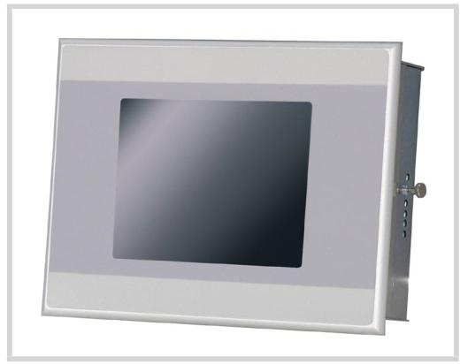
All Panel 800 Version 6 are developed to satisfy the demands of human-machine communication. Built-in functions such as displaying and controlling text, dynamic indication, time channels, alarm and recipe handling are included.
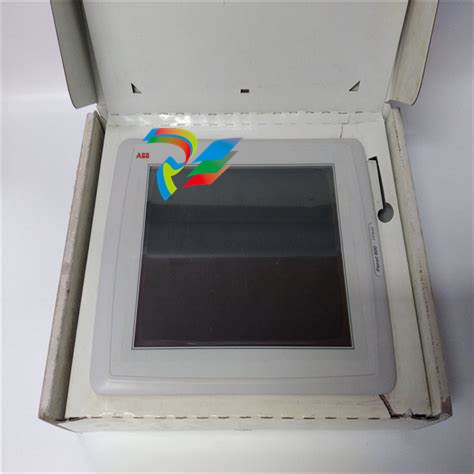
ABB-PP877/3BSE069272R2Touch Screen
During Installation • The operator panel is designed for stationary installation on a planar surface, where the following conditions are fulfilled: – no high explosive risks – no strong magnetic fields – no direct sunlight – no large, sudden temperature changes • Install the operator panel according to the accompanying installation instructions. • Ground the operator panel according to the accompanying installation instructions. • Only qualified personnel may install the operator panel. • Separate the high voltage, signal and supply cables. • Make sure that the voltage and polarity of the power source is correct before connecting the operator panel to the power outlet. • Peripheral equipment must be appropriate for the application and location. • In a Zone 2 environment, this equipment shall be installed in an enclosure that provides a degree of protection not less than IP 54 or greater than IP 65 in accordance with IEC/EN 600079-0. The IP rating of the equipment is limited to the IP rating of the enclosure it is to be installed into. • In a Zone 22 environment, this equipment shall be installed in an enclosure that provides a degree of protection not less than IP 64 or greater than IP 65 in accordance with IEC/EN 600079-0. The IP rating of the equipment is limited to the IP rating of the enclosure it is to be installed into.
Installation Process The following is needed: • A Phillips/slot screwdriver 1. Unpack and check the delivery. If damage is found, notify the supplier. 2. Place the operator panel on a stable surface during installation. Dropping the operator panel or letting it fall may cause damage. 3. To cut a correct opening for the operator panel, use the cut out dimensions in the outline drawing. For more information, see sections Operator Panel Drawings and Technical Data. 4. Secure the operator panel in position using all the fastening holes and the provided brackets and screws:
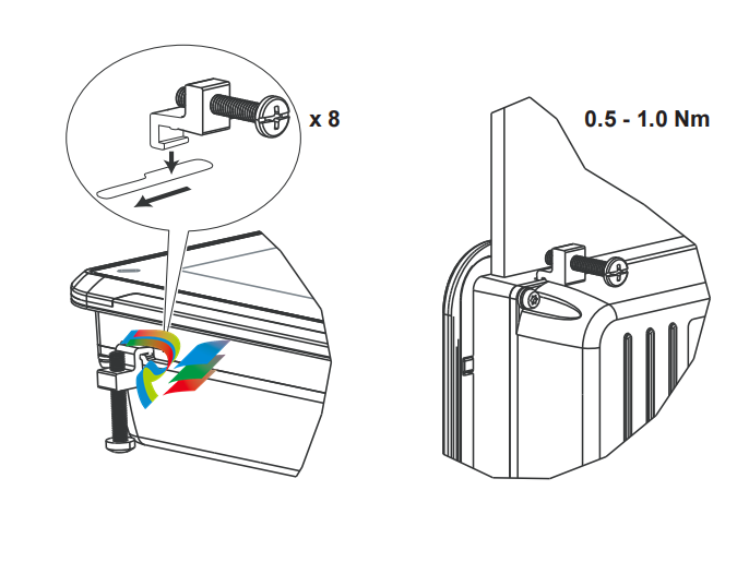
5. Connect the cables in the specified order, according to the drawing and steps below. • The operator panel must be brought to ambient temperature before it is started up. If condensation forms, ensure that the operator panel is dry before connecting it to the power outlet. • Ensure that the operator panel and the controller system have the same electrical grounding (reference voltage level), otherwise errors in communication may occur. • Ensure that the voltage and polarity of the power source is correct. • Separate high voltage cables from signal and supply cables. • Shielded communication cables are recommended.
In some industrial units for Ethernet, the RJ45 contact’s shield is connected to the chassis via a capacitor, see 1 in drawing above. The operator panel’s Ethernet shield is directly connected to the chassis, see 2 in drawing above. 1. Check whether the other Ethernet unit has its shield directly grounded or grounded via a capacitor. In many cases, connecting the shielded Ethernet cabling to the chassis at both ends is inappropriate. Hum or grounding loops can occur. Unshielded cabling may even result in fewer communication errors. A good solution may be to use a shielded Ethernet cable, but to connect the shield at one end only. One option is to break the shield, see 3 in drawing above.
To Achieve Better EMC Protection • Use shielded cables for RS232 communication. • Use twisted pair and shielded cabling for RS422 and RS485. • Use the cabling intended for the bus type; Ethernet, Profibus, CC-Link, CAN, Device Net etc. • Install and connect according to applicable specifications for the relevant bus standard. • Use shielded cabling for Ethernet, preferably with foil and a braided shield. • D-sub covers should be shielded, and the shield should be connected to the cover 360° where the cable enters. • Connect the shield at both ends. Shielded cable Not same potential Ground plane 1 Ground plane 2 Ground plate Ground plate in another building 0.1 μF/250 V With longer distances, there is a risk that the ground potential may be different. In that case, the shield should only be connected at one end. A good alternative is to connect the other end of the shield to the ground via a 0.1 µF/250 V plastic capacitor. Both ends are then connected to the ground in terms of HF, but only connected to the ground at one end in terms of LF, thus avoiding the 50/60 Hz grounding loops.
Metal cabinet Metal cabinet Terminal or connector Terminal or connector EMC cable gland Plastic cable gland Shielded cable Cable clamp in steel Shielded cable
| User name | Member Level | Quantity | Specification | Purchase Date |
|---|


-
 ABB medium voltage frequency converter ACS2000 4kV frame 1, 2, 3 spare parts
 -
 ABB low-voltage AF contactor AF400... AF460
 -
ABB KPM Sheet Break Detector - KB2
-
 ABB TP854 base plate
 -
 ABB AO845A Analog Output Module
 -
 ABB FS450R12KE3+AGDR-71C Integrated Circuit
 -
 ABB PNI800K01 Ability ™ Symphony ® Plus Hardware Selector
 -
 ABB REA 101 arc protection relay
 -
 ABB 3BSC950193R1 TB850 CEX-Bus Terminator
 -
 ABB BC810K02 Compact Product Kit Hardware
 -
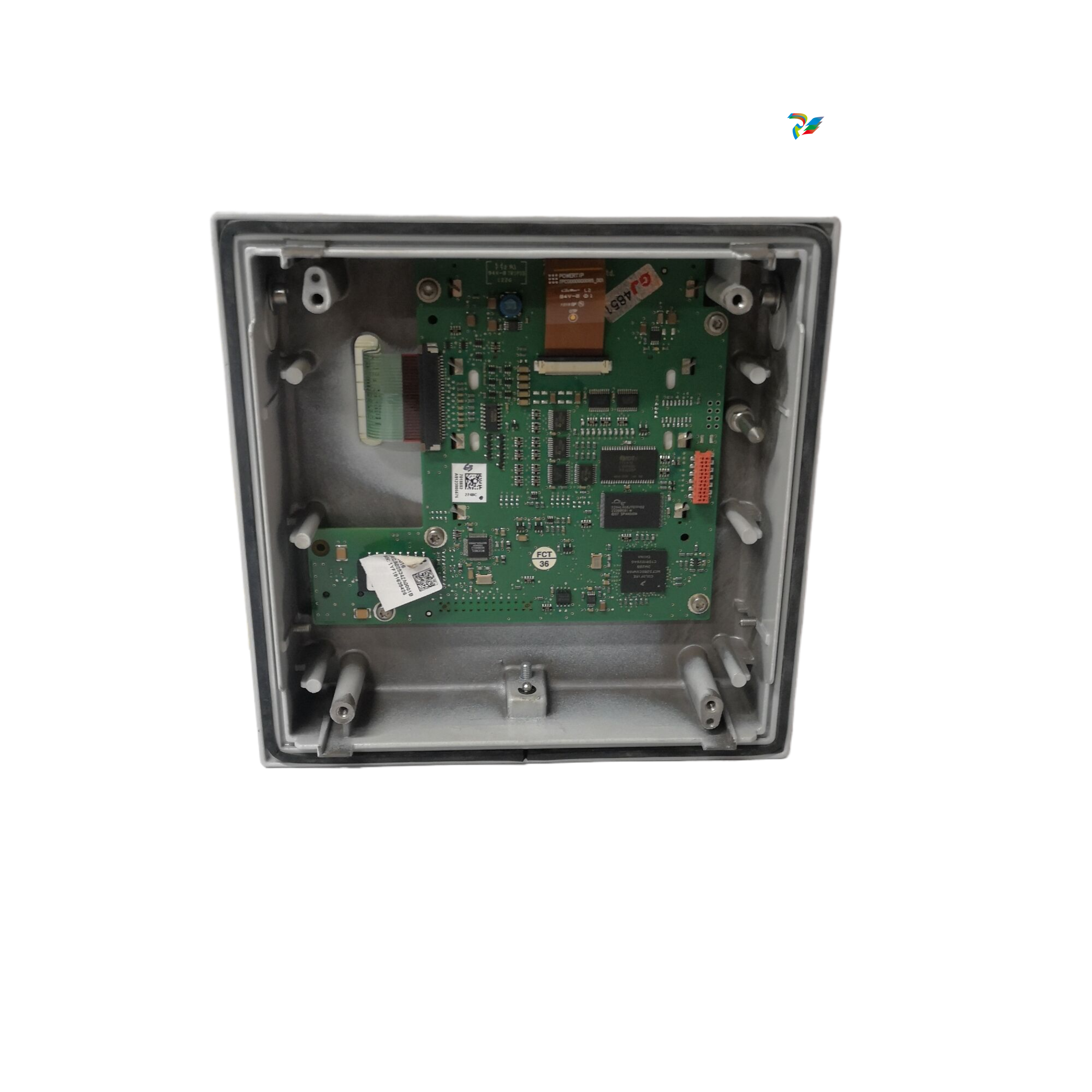 ABB DI810 digital input module
 -
 ABB Harmony Sequence of Events (SOE) system
 -
 ABB Tension Electronics PFEA111/112
 -
 ABB AI801 Analog Input Module
 -
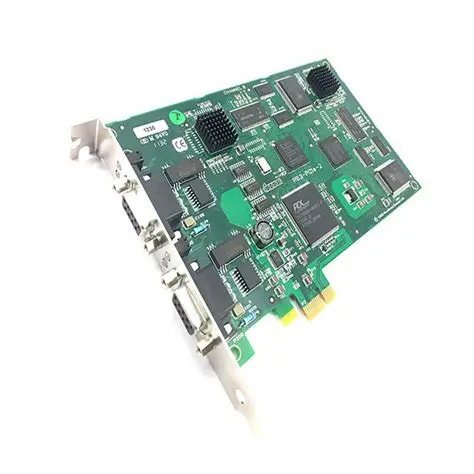
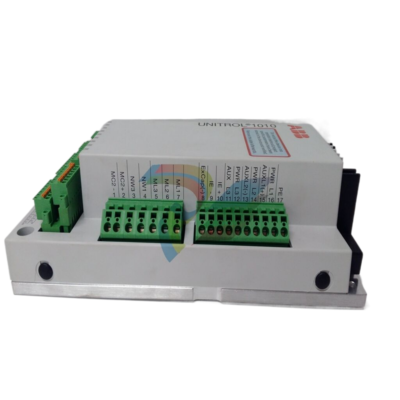 ABB AF C094 AE02 ARCnet Control Board
 -
 ABB TP830-1 PLC module
 -
 ABB CP430 Human Machine Interface (HMI) Installation and Operation
 -
 ABB 81EU01-E/R3210 Analog Signal Input Module
 -
 ABB Panel 800- PP836 5.1 Hardware and Installation
 -
ABB PM866AK01 Controller
-
 ABB TK850V007 CEX Bus expansion cable Installation and configuration method
 -
ABB AO801 Analog Output Module
-
ABB CI855 communication interface
-
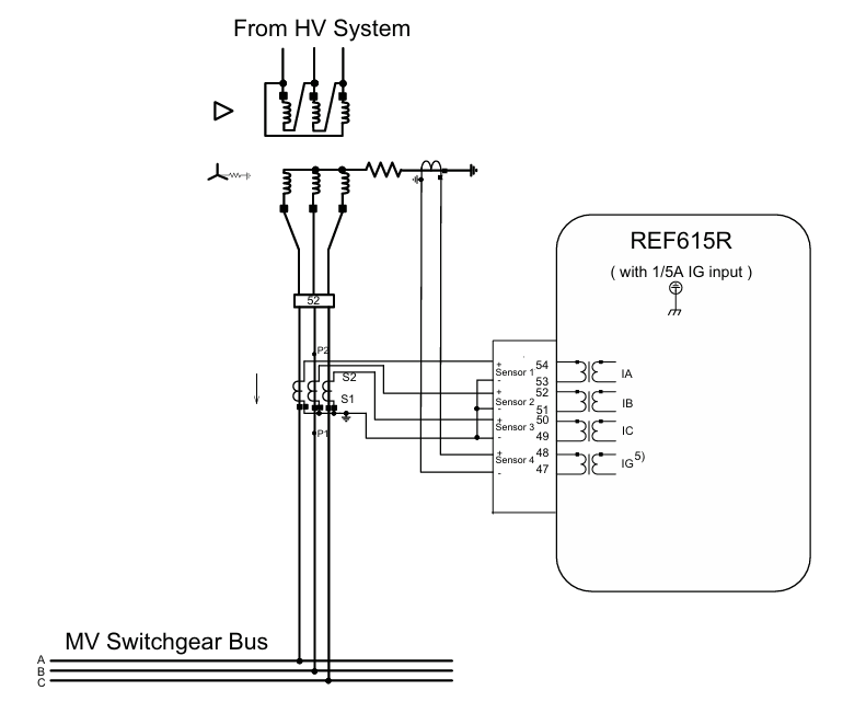 ABB REF615R feeder protection and control
 -
 ABB EL3020 Model EasyLine Continuous Gas Analyzers
 -
 MOLEX SST-PB3-VME-1 and SST-PB3-VME-2 Hardware Reference Guide
 -
 Eaton XVH300 MICRO PANEL
 -
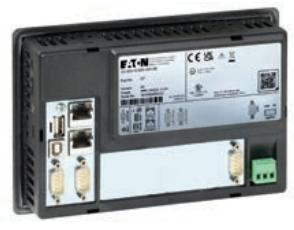 Eaton XV-303/XV-313 multi touch display
 -
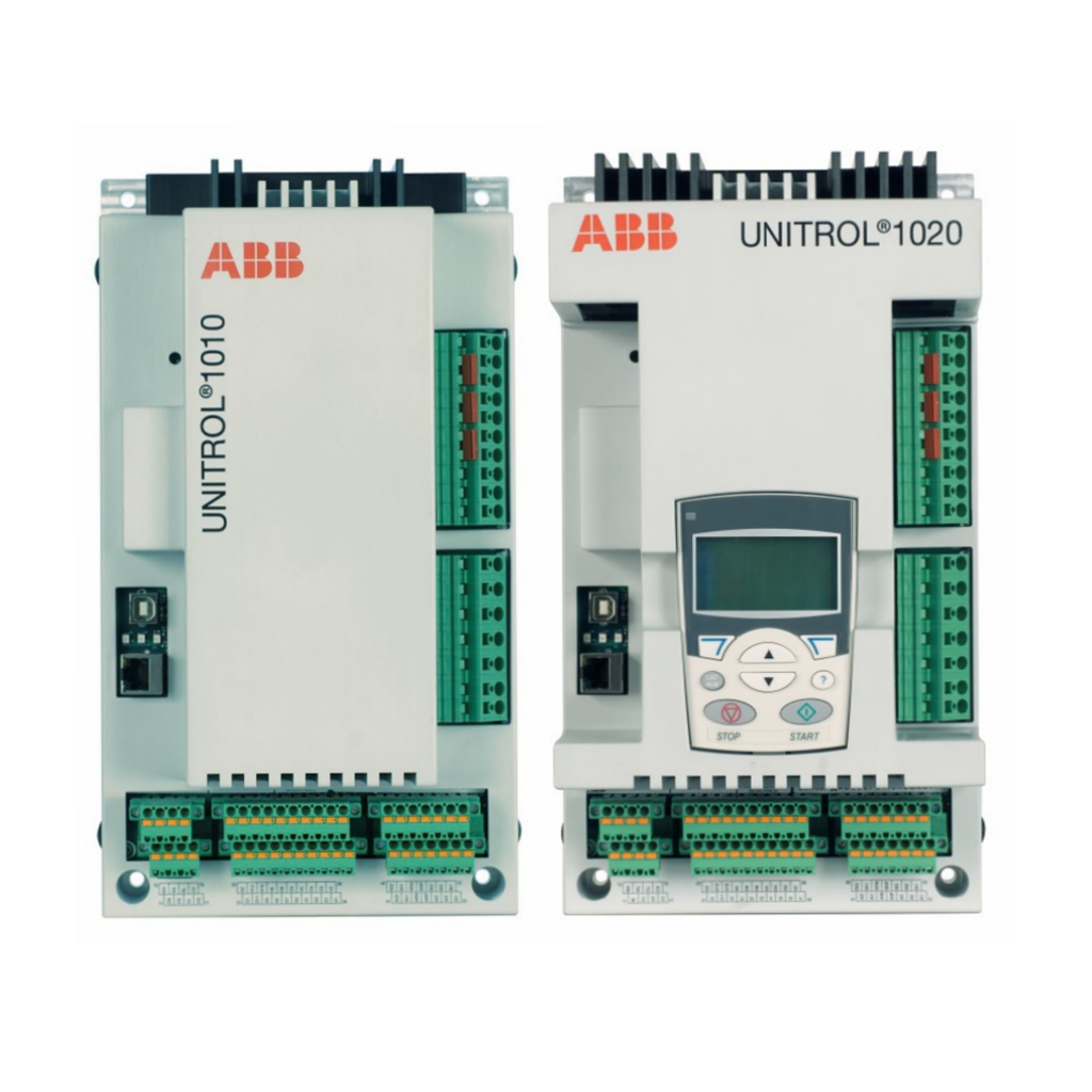 ABB Panel 800 Version 6 Operator Panel
 -
 ABB 1SVR011718R2500 Analog Signal Converter
 -
 ABB BC810K02 CEX Bus Interconnection Unit Kit
 -
 ABB RELION ® 615 series REU615 voltage protection and control relay
 -
 ABB Symphony Harmony/INFI 90 DCS Remote I/O Module Upgrade Kit
 -
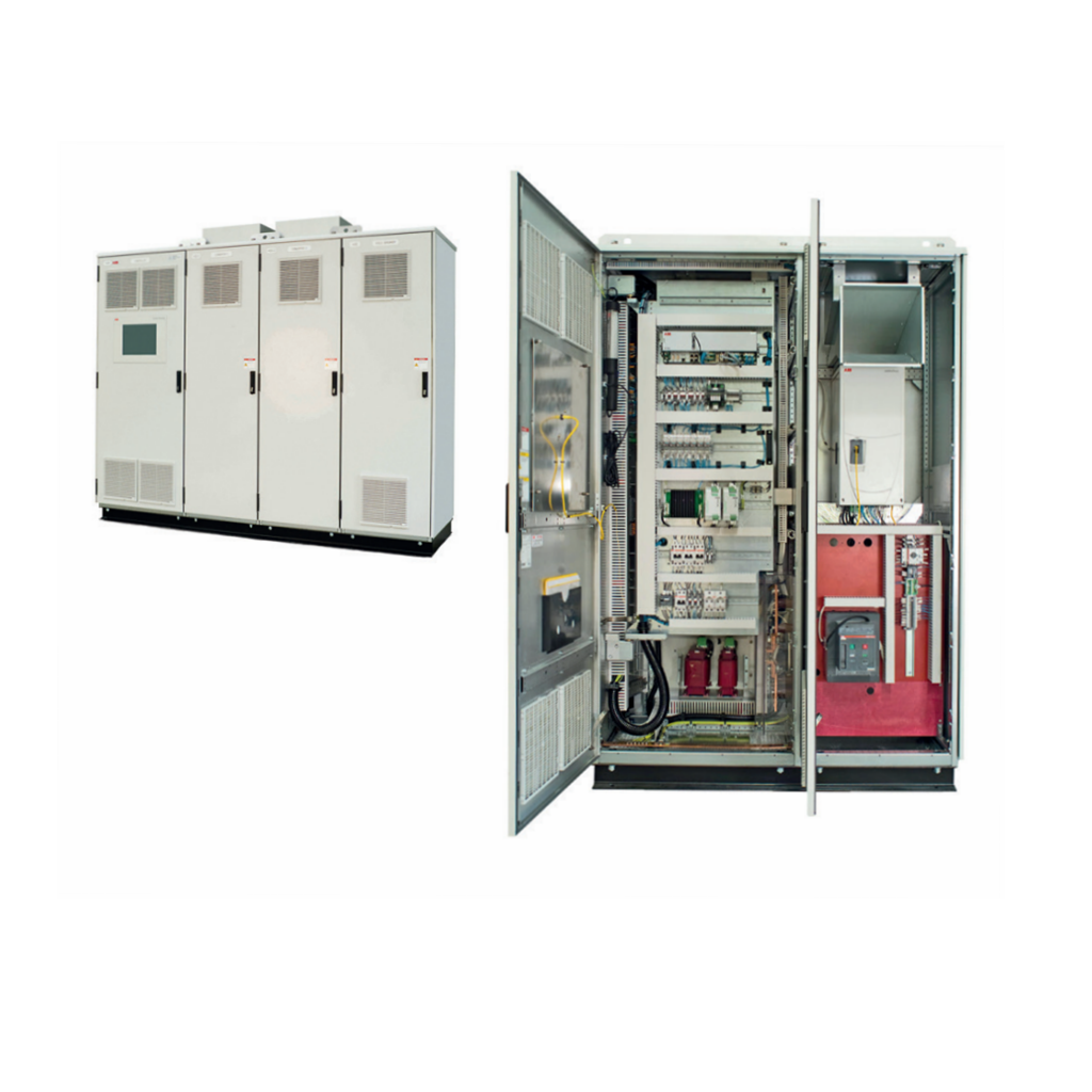 ABB REM610C55HCNN02 motor protection relay
 -
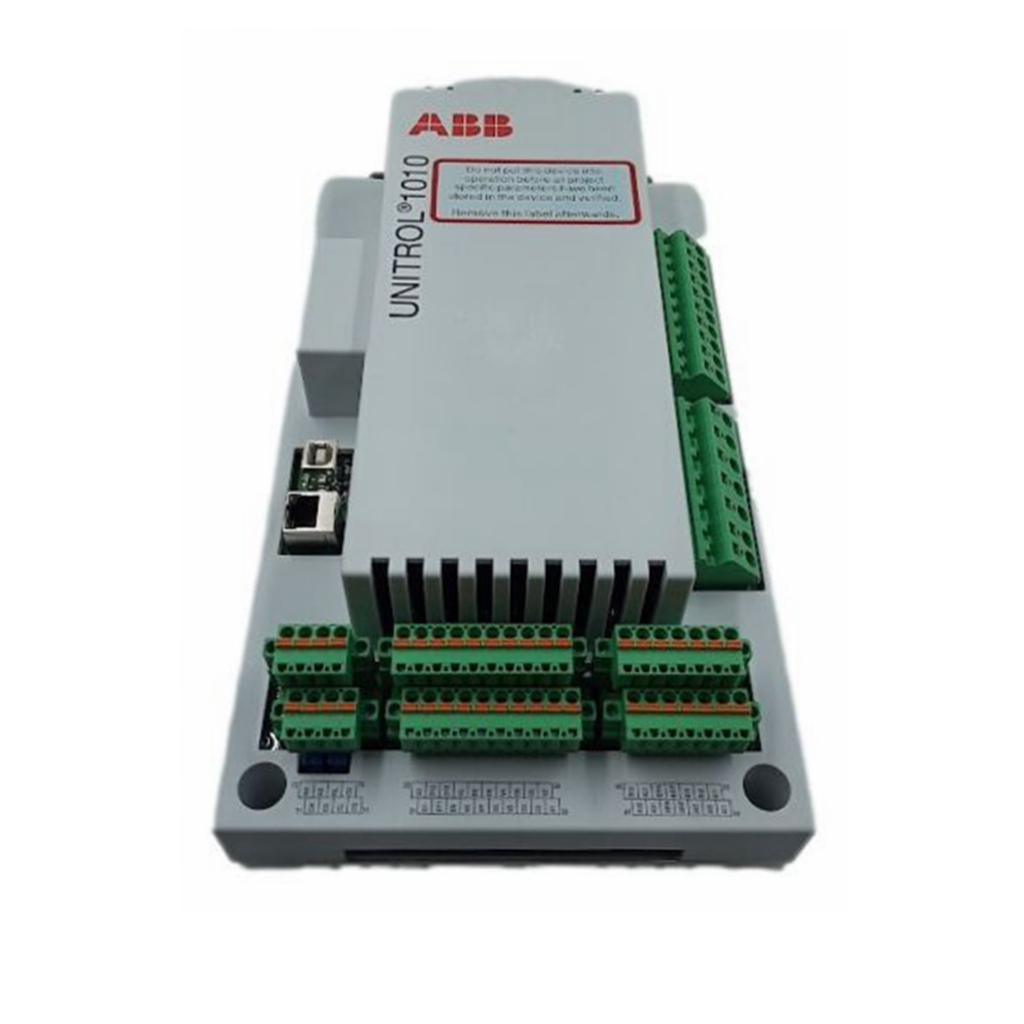 ABB TU810V1 Compact Terminal Unit
 -
 ABB REF 541, REF 543, and REF 545 feeder terminals
 -
ABB UNITOL 1000 series automatic voltage regulator
-
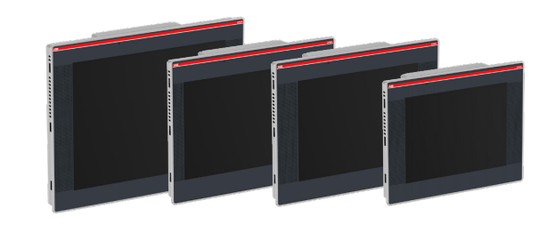 ABB PCD235C101 3BHE057901R0101 AC800pec Excitation High Performance Control System
 -
ABB GFD233 3BHE022294R0102 Redundant System Control Module
-
 Galil DMC-40x0 series motion controller
 -
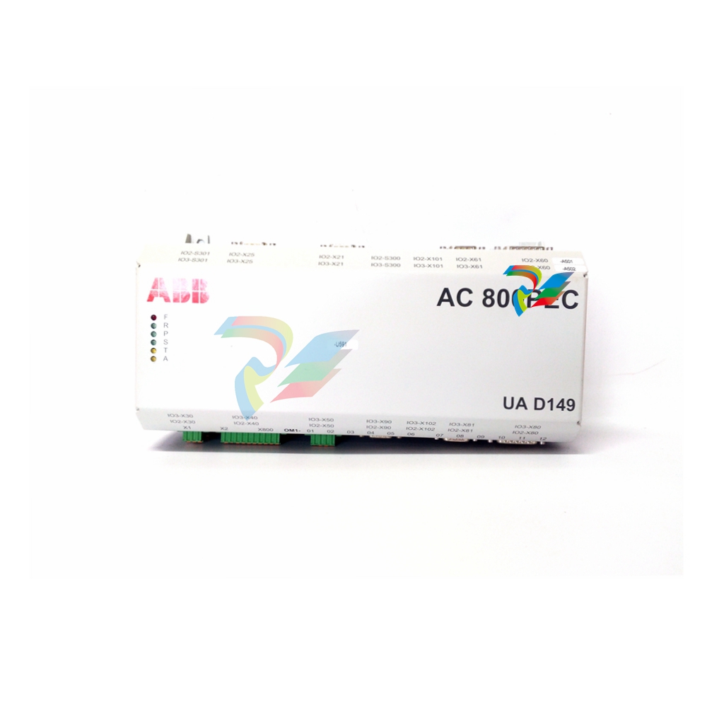 ABB AO2040-CU Ex Central Unit
 -
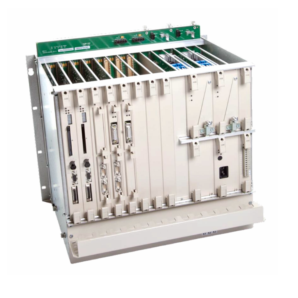 ABB REF615 feeder protection relay
 -
 ABB INSUMMCU2 MCU2A02V24 motor control unit
 -
 ABB REF 542plus multifunctional protection and switchgear control unit
 -
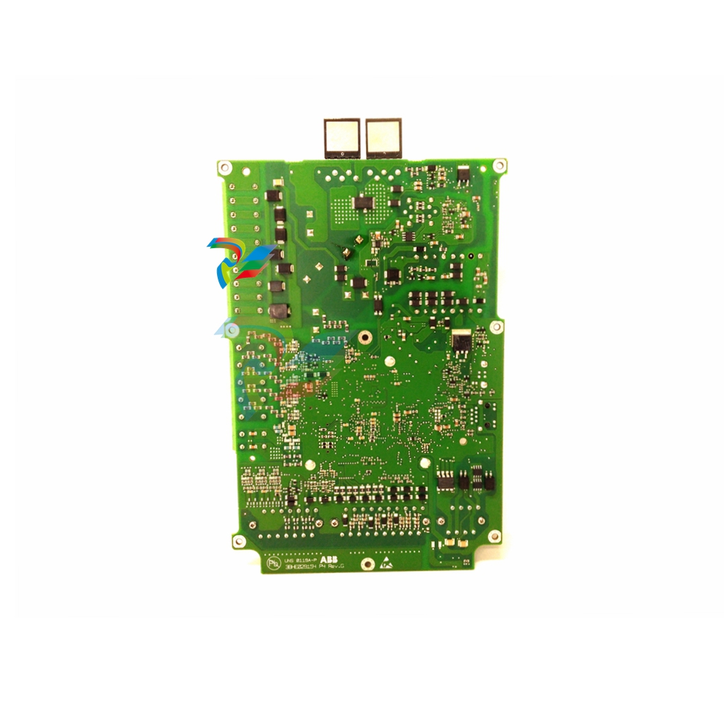 ABB PP886 Compact Product Suite hardware selector
 -
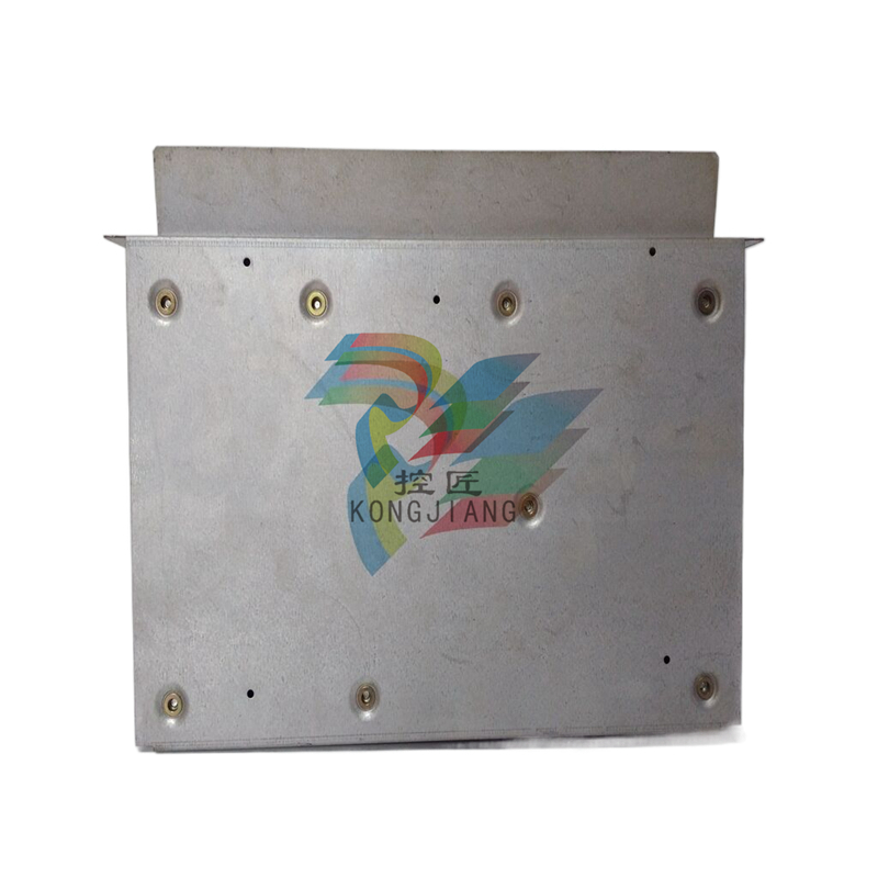 ABB AC500 V3 PLC Enhanced connectivity and performance
 -
ABB SYNCHROTACT ® 5 Synchronous and Parallel Devices
-
 ABB SUE 3000 high-speed switching device
 -
 ABB REF542plus multifunctional protection and switchgear control unit
 -
 ABB Relion ® 615 series REF615 feeder protection and control device
 -
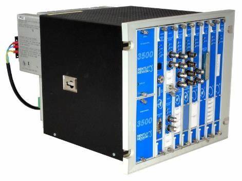
 Bentley 3500/45 Position Monitor
 -
Bentley 3500/42 Proximitors ®/ Earthquake monitoring module
-
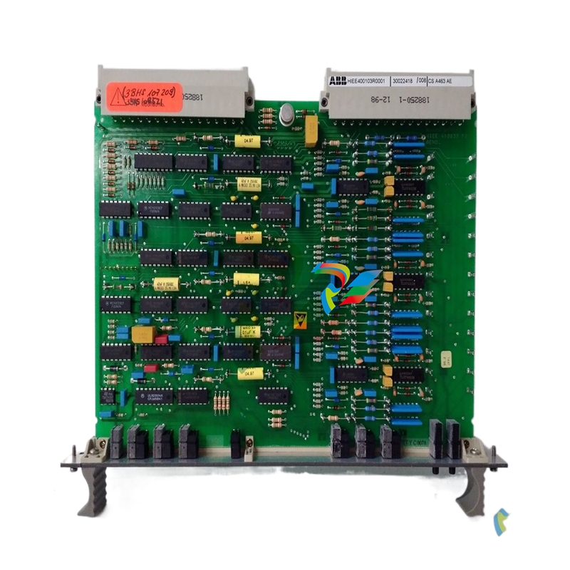 ABB molded case circuit breaker
 -
 ABB MVME162 Embedded Controller
 -
 ABB TU810V1 System 800xA hardware selector
 -
 ABB SPAJ 140 C overcurrent and ground fault relay
 -
ABB AC 800PEC High Performance Control System
-
ABB REF601 and REJ601 relays
-
 ALSTOM RPH3/PS125b Controlled Switching Device,CT1VT220/TCR
 -
ABB V-Contact VSC Medium voltage vacuum contactors
-
ABB 3BHE004385R0001 UNS 0884a, V1:Current Sensor 2000A
-
ABB UAD206A101 Programmable Logic Controller
-
 ABB ACS800-04/U4 driver module
 -
 ABB UAD149A0011 3BHE014135R0011 Controller Module
 -
 ABB BSM series AC servo motor
 -
 ALSTOM DFI-150-0003- Limelight Diagnostic Board
 -
 ABB GCC960C102 motor driver
 -
 ABB INDUSTRIALDRIVES UCU-22, UCU-23 andUCU-24control units
 -
ABB XDD501A101 Bus Terminal Module
-
 ABB S800 I/O DTM 5.3 module
 -
 ALSTOM N897164611M High Performance Control Module
 -
 ALSTOM N897164610L Pulse Output Module
 -
 ALSTOM N70032702L High Performance Control Module
 -
 ALSTOM MVAJ1L1GB0771B Auxiliary Transmission Relay
 -
 GE 239 MOTOR PROTECTION RELAY
 -
 ALSTOM ADVANCED MICRO CONTROLLER 2
 -
 Honeywell HC900 Process and Safety Controller
 -
ABB ControlMaster CM10 Universal Process Controller
-
ABB dual power conversion switch
-
 ABB RET 541/543/545 Transformer Terminal Device
 -
 ABB Relion ® RET620 Transformer Protection and Control Device
 -
 ABB Relion ® REU615 Voltage Protection and Control Device
 -
 ABB Relion ® REU615 Voltage Protection and Control Device
 -
 ABB REX615 Protection and Control Relay Products
 -
ABB PGC2000 series E2 process gas chromatograph
-
 ABB PROCOLOR P 88QT03 bus coupling module
 -
 Honeywell WEB-8000 Controller
 -
 ABB Protection Relay REX 521
 -
 ABB 5SGY3545L0020 Controller Module
 -
ABB 5SGY3545L0017 module tension controller
-
ABB 5SGY3545L003 IGCT control module
-
ABB SNAT609TAI 5761789-6H Industrial I/O Interface Card
-
ABB SNAT602TAC circuit board
-
ABB SNAT603 CNT Control Board
-
ABB SNAT634PAC pulse amplifier module
-
 ABB RK682011-BA RL0B 100 standard unit module
 -
 ABB PP846A 3BSE042238R2 Industrial Control Panel
 -
 ABB ZMU-02 inverter memory card
 -
ABB 3BHE014135R0011 UAD149A0011 DCS POSITIONING CONTROL MODULE
-
ABB 3BHE014135R0011 UAD149 A00-0-11 I/O module
-
 ABB MEASUREMENT & ANALYTICS Web Tension Systems with Tension Electronics PFEA113
 -
ABB GDD471A001 2UBA0022R0001 motor control module
-
ABB UCD224A103 high-performance control module
-
 ABB PDD205A0121 control module
 -
ABB PDD205A1121 3BHE02535R1211 processor module
-
ABB DSDX453 Digital Input/Output Module
-
ABB DSPC454 controller module
-
 Woodward ESDR4 Current Differential Protection Relay
 -
 Siemens SIJECT CI16iP StepB 6AТ1131-6DF21-0AB0 Compact Control
 -
 EtherNet/IP™ to Remote I/O or DH+ Gateway AN-X2-AB-DHRIO
 -
ABB 81EU01-E/R3210 Analog Signal Input Module
-
 ABB TK457V050 Industrial Temperature Controller
 -
 ABB DSRF197K01 Control Module
 -
 ABB TK802F SD802F/SD812F power cord
 -
ABB 3BHE03930R0101 I/O module
-
ABB 3BHB0040277R0101 GVC700AE01 thyristor module
-
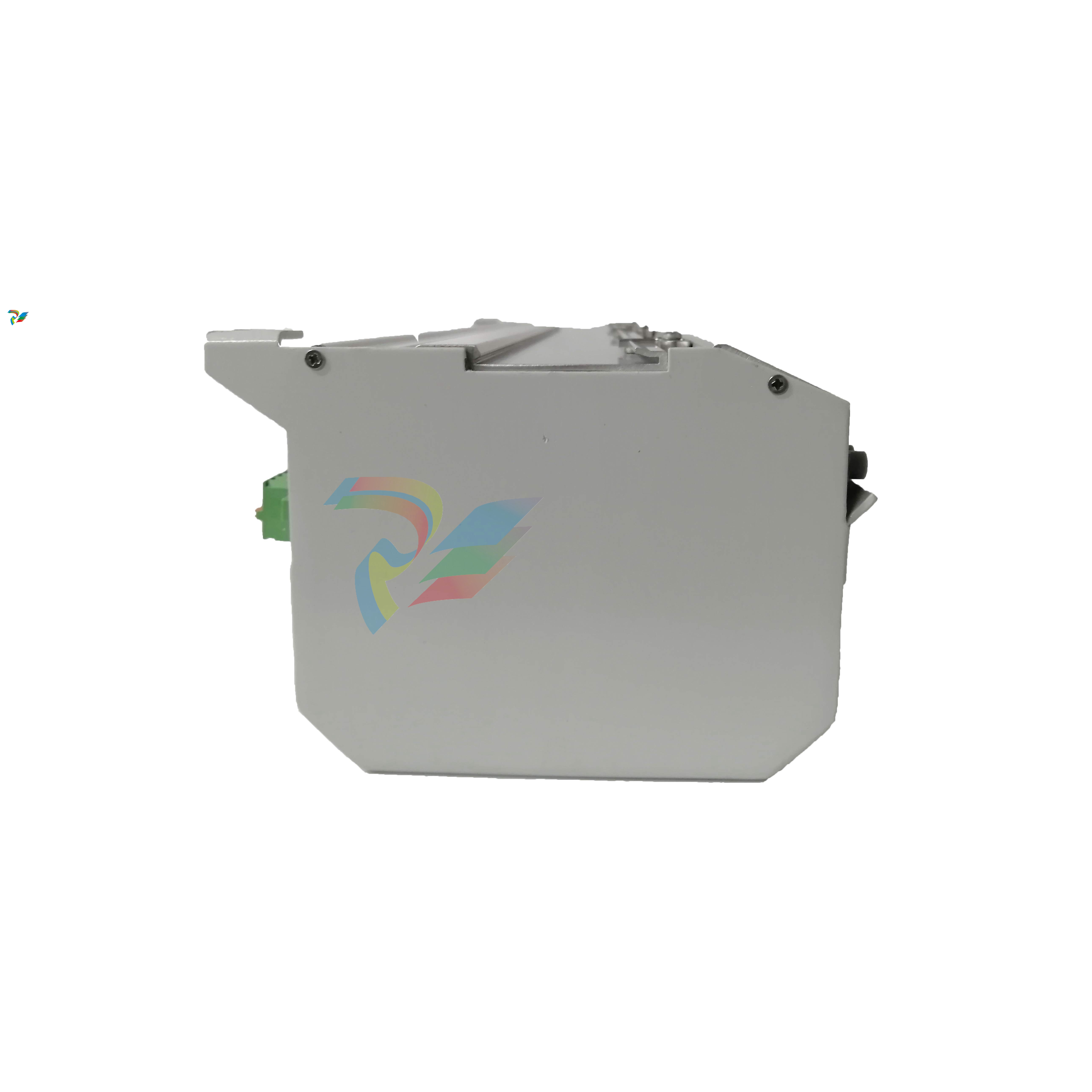 ABB 3BHB003154R0101 5SXE05-0156 IGCT module
 -
 RELIANCE INSPECTOR VCIB-06 Advanced Industrial Visual Display
 -
ABB AO2000-LS25 Laser analyzer
-
 HIMA F8650X Central module
 -
ABB PM864AK01 Classic System 800xA hardware selector
-
ABB 3BSE048845R1 CI868K01 IEC 61850 Interface
-
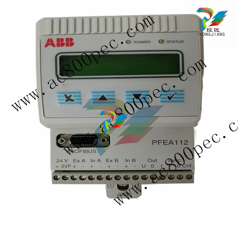 ABB 5SHY35L4520 Asymmetric Integrated Gate Converter Thyristor
 -
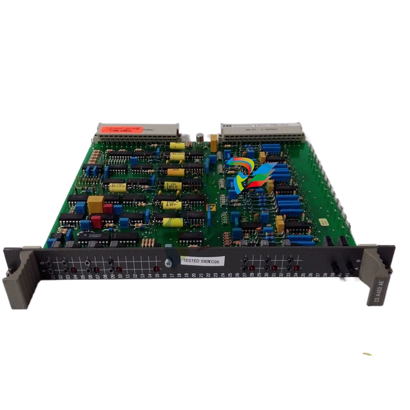 ABB UNS0119A-P V101 3BHE029153R0101 processor module
 -
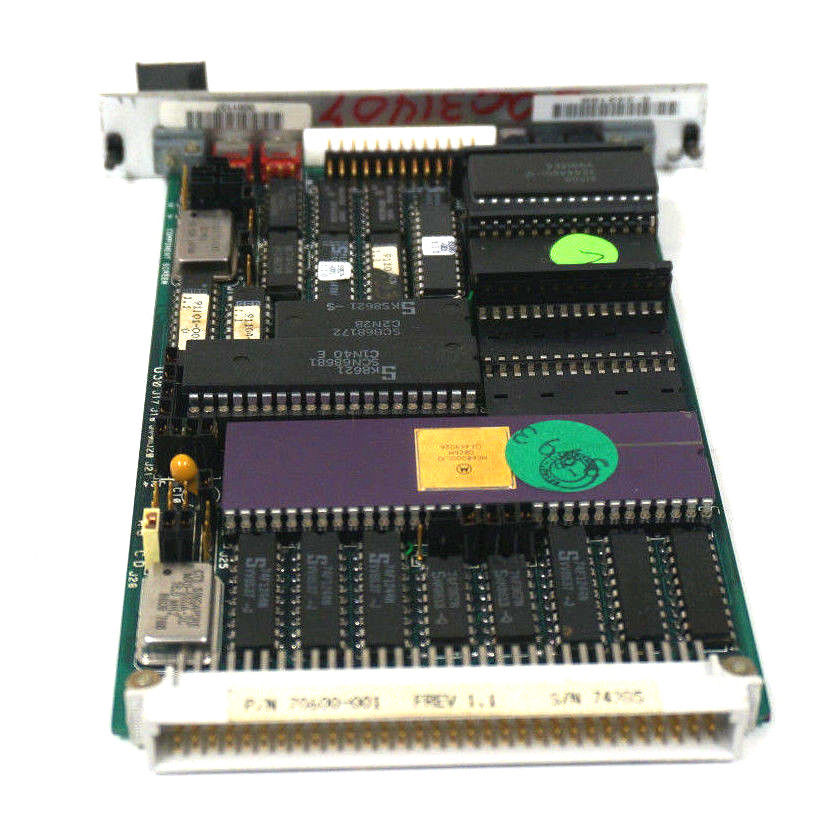 Xycom 99212A-001 PC board
 -
 Xycom 144365-001 motherboard
 -
 XYCOM 70400-001 T3065-4 XVME-400 Board
 -
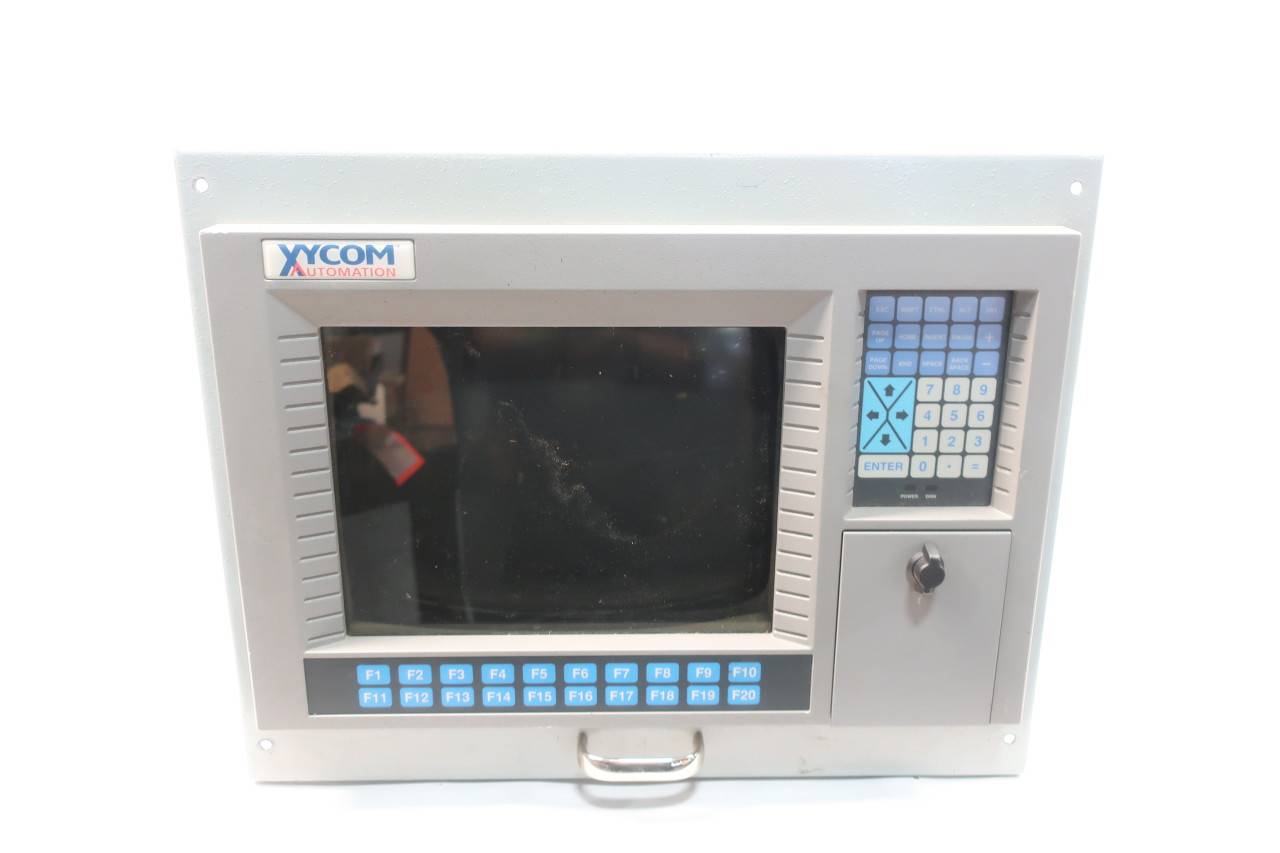 Xycom Automation # 9450-2480016010000 Interface Monitor Model

