
K-WANG


- Telephone:+86-15305925923
- contacts:Mr.Wang
- Email:wang@kongjiangauto.com
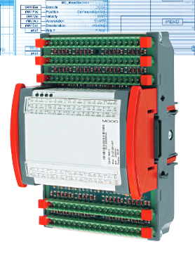
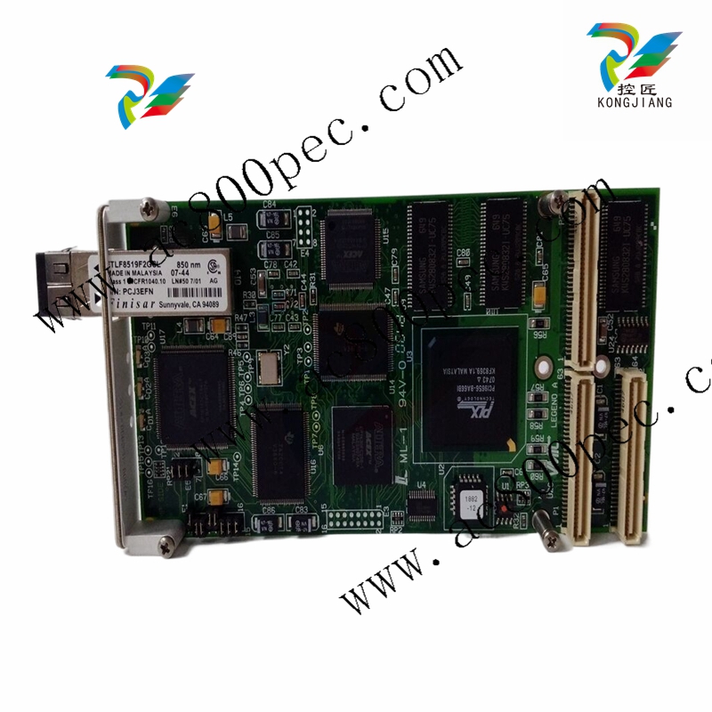
GE VMIVME-2210 Relay Board
GE VMIVME-2210 Relay Board
Functional Characteristics
Introduction:
The VMIVME-2210 provides 64 One Form C (SPDT) contacts to the user via two 96-pin DIN connectors. These relays are the magnetic latching type which means that, once a contact is set it will remain set (even if power is removed from the relay) until it is reset. All three contact points are brought out via the connector. They are the N.O. (Normally Open), N.C. (Normally Closed), and the Common contact points. The N.O. and the Common can be used to create One Form A contacts while the N.C. and common can be used as One Form B contacts. This arrangement permits 64-conductor cables to be used for Form A switches.
The VMIVME-2210 is populated with double pole relays, but only one pole is brought out to the user. The other pole is used by the Built-in-Test (BIT) logic. The state of the controlling Data Registers or the N.C. poles is read during read accesses of the board. The Control Registers are located at the same address as the relays. This allows the user to monitor both the state of the user contacts and the Control Registers. Because the read pole and the user’s pole are controlled by the same coil, BIT can monitor the user’s contacts via the N.C. contacts of the second pole.
Board Functions:
Sixty-four one Form C latching relay contacts via two 96-pin DIN connectors. One extra set of contacts (the N.C. set) is used for BIT. Latching relays hold their state (even with power removed) until commanded to change.
Compliance:
The VMIVME-2210 conforms to the ANSI/IEEE STD 1014-1987 IEC 821 and 297 VMEbus specification with the following mnemonics: A24, A16: 3D/39, 2D/29: D32, D16, D08(EO): Slave.
Addressing Scheme:
The base address of this board contains the board ID. Stacked above this 16-bit word is a 16-bit CSR. The Output Registers are placed at the next longword boundary above the CSR. Finally, the Contact Registers are stacked above the Output Registers. The Output and the Contact Registers are addressable as sixteen 8-bit bytes, eight 16-bit words, or four 32-bit longwords, located on any 128-bit boundary within standard data or short supervisory or nonprivileged I/O space.
Board Addressing:
Twenty jumpers are used to select the base address of the board. One jumper determines the address space (standard data or short I/O) of the board. Another chooses supervisory, nonprivileged, or either access mode. And the remaining 18 set up the base address of the board.
Built-in-Test: Board testing is accomplished by performing a read operation. Reading the address of the relay in question will place the state of its Data Register on the bus. Reading the Contact Register transfers the state of the second N.C. contact to the bus. Both the data controlling the relay and the contact state can now be compared. This is done because the relay takes so long (7 ms maximum) to change its state. With this information, the user can determine when the relay contacts have changed state.
Nonlatching Option:
If the nonlatching option is ordered, then standard relays are used. The contact data is not affected. However, the contacts will NOT hold when power is interrupted. This option will permit resets and power loss to place the relays in their normal position. Thus, N.O. contacts will open and the N.C. contacts will close. All other board operations are the same as those for the latching version
Features:
• Latching contacts will hold their state with power off
• Available in latching and nonlatching versions
• 1 Form C contacts (SPDT) with 96-conductor cable
• 1 Form A contacts (SPST) with 64-conductor cable
• 8-, 16-, or 32-bit data transfers
• Supports real time and offline fault detection and isolation
• 2.0A current rating
• Protection from relays changing during power up/down
| User name | Member Level | Quantity | Specification | Purchase Date |
|---|


KONG JIANG


Add: Jimei North Road, Jimei District, Xiamen, Fujian, China
Tell:+86-15305925923


