
K-WANG
+086-15305925923
Service expert in industrial control field!


Product
Article
NameDescriptionContent
Adequate Inventory, Timely Service
pursuit of excellence


Ship control system
Equipment control system
Power monitoring system
Brand
Product parameters
- Telephone:+86-15305925923
- contacts:Mr.Wang
- Email:wang@kongjiangauto.com
Description
This document is distributed for informational purposes only.
It is not to be construed as creating or becoming part of any
General Electric Company contractual or warranty obligation
unless expressly stated in a written sales contract.
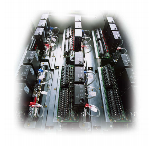
GE FANUC Mark* VIe Control
Mark* VIe is a flexible control system for multiple applications. It features high speed, networked I/O for simplex, dual, and triple redundant systems. Industry standard Ethernet
communications are used for I/O, controllers, and supervisory
interface to operator and maintenance stations, and third-party systems.
ToolboxST* is used for Mark VIe and related controls as a common software
platform for programming, configuring I/O, trending, and analyzing diagnostics. It
provides a single source of quality, time-coherent data at the controller and plant
level for effectively managing equipment assets.
A single-board controller is the heart of the system. It includes the main processor
and redundant Ethernet drivers for communicating with networked I/O and
additional Ethernet drivers for the control network. A QNX® real-time, multitasking
operating system is used for the main processor and I/O. Application software is
provided in a configurable control block language, and is stored in non-volatile
memory. It conforms to IEEE-854 32-bit floating-point format.
IONet is a dedicated, full-duplex, point-to-point protocol that provides a
deterministic, high-speed 100 MB communications network suitable for local or
remote I/O with a fiber interface. It provides communication between the main
processor(s) and networked I/O blocks, called I/O packs.
100 MB Ethernet is used for
communication to local and
remote I/O packs. The IONet
is available in single, dual,
and triple configurations.
Each I/O pack is mounted on a board with barrier or box-type terminal blocks. The
I/O pack contains two Ethernet ports, a power supply, a local processor, and a data
acquisition board. Computation power grows as I/O packs are added to the control
system, enabling an overall control system frame rate of 10 ms in simplex, dual, or
triple redundant configuration. Some process sub-systems require even more
performance; therefore, the local processors in each I/O pack run algorithms at
higher rates as required for the application.
Redundancy
Every application has different requirements for redundancy depending on the
importance of the process. Mark VIe provides a wide range of redundancy options
that can be supplied in virtually any combination and mounted local or remote. Some
of these redundancy options include:
• Power sources and supplies single, dual, and triple
• Controllers (main processor) single, dual, and triple
• I/O network redundancy single, dual, and triple
• I/O packs per terminal board single, dual, and triple
• Ethernet Ports / I/O pack single or dual
Controllers are continuously online and read input data directly from IONet. Dual
redundant systems transmit inputs from one or redundant I/O packs on dual IONets
to dual controllers. Outputs are transmitted to an output I/O pack that selects either
the first healthy signal or the signal of choice. Three output packs can be provided to
vote output signals for mission-critical field devices.
Dual redundant systems can be configured for single, dual, and triple sensors. Their
dual internal networks and controllers keep the process online if a controller or
power supply fails. Triple redundant systems are available to protect against soft or
partial failures of devices that continue to run but with incorrect signals/data.
These systems out vote a failed component with a 2-out-of-3 selection of the signal.
Application software in all three controllers runs on the voted value of the signal
while diagnostics identify the failed device. These sophisticated diagnostics
minimize the mean-time-to-repair (MTTR) while the on-line repair capability
maximizes the mean-time-between-forced-outages (MTBFO). Field sensors for these
systems can be single, dual, or triple.
A second controller can be provided to separate the application software for different
pieces of equipment. For example, a core engine control for an air-fuel governor can
run in one controller while a second controller can be dedicated to auxiliary control.
Note Every I/O pack communicates directly on IONet, which enables each I/O pack
to be replaced individually without affecting any other I/O in the system. Also, the
I/O pack can be replaced without disconnecting any field wiring.
I/O Interface
One or multiple I/O packs are mounted on each board to digitize the sensor signal,
perform algorithms, and communicate with a separate controller that contains the
main processor. I/O packs have a local processor board that runs a QNX operating
system and a data acquisition board that is unique to the type of input device. Local
processors run algorithms at faster speeds than the overall control system.
An on-board temperature sensor
provides continuous monitoring of
the environment in remote
locations.
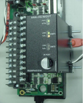
An infrared transceiver is useful for low-level diagnostics. I/O values can be
monitored, I/O pack host/function names can be programmed, and error statuses can
be checked. This requires a Windows®-based diagnostic tool on a laptop or a
handheld computer.
• Dual 100 MB Ethernet ports
• 100 MB full duplex ports
• Online repair per I/O pack
• Operation -30°C to 65°C (-22 °F to 149 °F)
• Accuracy -30°C to 65°C (-22 °F to 149 °F)
• I/O packs rated Class 1, Div. 2
• Ambient temperature sensor
• LEDs: power status and attention
• LEDs: Ethernet link-connected and communication-active
• LEDs: application-specific
• Processor: 32-bit RISC CPU 266 mHz
• Infrared Transceiver: Low level diagnostics, monitor I/O,
set host/function names, error status
• Power: 28 V dc (typical)
• Internal solid-state circuit breaker and soft start
The I/O Processor contains a temperature sensor that is accurate to within ±2°C
(±3.6 °F). Detection of an excessive temperature generates a diagnostic alarm, and
the logic is available in the database (signal space) to facilitate additional control
action or unique process alarm messages. In addition, the temperature is
continuously available in the database.
A power supply provides a regulated 28 V dc power feed to each I/O pack. The
negative side of the 28 V dc is grounded through the I/O pack metal enclosure and its
mounting base. The positive side has solid-state circuit protection built-into the I/O
pack with a nominal 2 A trip point. Online repair is possible by removing the
28 V dc connector, replacing the I/O pack, reinserting the power connector, and
downloading software from the software maintenance tools.
Note Every I/O pack communicates directly on IONet, which enables each I/O pack
to be replaced individually without affecting any other I/O in the system. Also, the
I/O pack can be replaced without disconnecting any field wiring.
Terminal Blocks
Signal flow begins with a sensor connected to a terminal block on a board. There are
two types of boards available. T-type boards contain two 24 point, barrier-type,
removable, terminal blocks. Each point can accept two 3.0 mm2
(#12AWG) wires
with 300 V insulation per point with spade or ring type lugs. In addition, captive
clamps are provided for terminating bare wires. Screw spacing is 9.53 mm (0.375
inch) minimum, center-to-center.
A shield strip is provided next to each block, which is actually the left-hand side of
the metal base where the board is mounted. Wide and narrow boards are arranged in
vertical columns of high and low-level wiring that can be accessed from top and/or
bottom cable entrances. An example of a wide board is a board that contains
magnetic relays with fused circuits for solenoid drivers. T-type boards are normally
surface mounted, but can also be DIN-rail mounted.
Barrier and Box Type Boards with I/O Packs
S-type boards have one I/O pack for simplex and dual redundant systems. They are
half the size of T-type boards and are DIN-rail or surface mounted. Two versions of
the boards are available, H1 and H3. H1 boards have fixed terminal blocks, and H3
boards have removable terminal blocks. A H2 version is available for mounting of
custom blocks such as spring-cage or insulation displacement.
S-type boards have box type terminal blocks that accept one 3.0 mm2
(#12AWG)
wire or two 2.0 mm2
(#14AWG) wires with 300 V insulation per point. Screw
spacing is 5.08 mm (0.2 inch) minimum, center-to-center. A shield strip is provided
to the left of each block. It can be connected to a metal base for immediate grounding
or floated to allow individual ground wires from each board to be wired to a
centralized, cabinet ground strip.
Purchase history
| User name | Member Level | Quantity | Specification | Purchase Date |
|---|
Total 0 Record
Customer Reviews
Satisfaction :
5 Stars
No evaluation information


- other
- LTI Drives
- ADLINK
- Beckhoff
- Other Brands
- AMAT
- Iba
- PEPPERL+FUCHS
- Aerotech
- WATLOW
- MAN
- ADVANCED
- Abaco
- YOKOGAWA
- KOLLMORGEN
- MEGGITT
- kong-sberg
- METSO
- Motorola
- NI
- OEMAX
- RELIANCE
- scanlab
- schneider
- uniop
- Vibro-Meter
- Honeywell
- Rolls-Royce
- MOOG
- GE
- B&R
- Woodward
- Yaskawa
- xYCOM
- Siemens
- Emerson
- HIMA
- Bently
- ZYGO
- FOXBORO
- OMACO
- PROSOFT
- ENTERASYS
- TRICONEX
- Parker
- Lenze
- KEBA
- Alstom
- CTI
- ABB
- A-B
145

-
 ADLINK PCI-9112/cPCI-9112 multifunctional acquisition card
 -
 ADLINK PCI-8102 Two Axis Pulse Motion Control Card
 -
 ADLINK PCI-9812/PCI-9810 synchronous 4-channel high-speed acquisition card
 -
 ADLINK PCI-7200/cPCI-7200 high-speed digital I/O board
 -
 ADLINK MXE-1000 series fanless embedded machine
 -
 ADLINK IMB-T10 Mini ITX Industrial Motherboard
 -
 ADLINK HSL Distributed High Speed I/O System
 -
 ADLINK PXI/DAQ/DAQe-2500 series multifunctional analog output DAQ card
 -
 ADLINK PXI/DAQ/DAQe-2200 series multifunctional data acquisition card
 -
 ADLINK ETX-AT ETX Core Computer Module
 -
 ADLINK ACL-7225 ISA 16 channel relay output+16 channel isolated digital input card
 -
 ADLINK DAQ-2000 series synchronous acquisition card
 -
 ADLINK NuPRO-E330 PICMG 1.3 full-length industrial motherboard (SHB)
 -
 ADLINK ACL-8112 series multifunctional ISA acquisition card
 -
 ADLINK USB-2405 24 bit dynamic signal acquisition module
 -
 ADLINK PXIS-3320 15 slot 6U PXI chassis
 -
 ADLINK PCIe GIE7x series acquisition card
 -
 ADLINK PCIe-7856/PCIe-7853 Distributed Motion and IO Main Controller PCIe Acquisition Card
 -
 ADLINK PCI-6308 series isolated analog output board
 -
 ADLINK PCI-7432 Isolated Digital I/O Acquisition Card
 -
 ADLINK NuPRO-E72 PICMG 1.3 Full length Industrial SHB Single Board Computer
 -
 ADLINK MXE-5400 series fanless embedded industrial computer
 -
 ADLINK M-322 Industrial ATX Motherboard
 -
 ADLINK IMB-M43H Industrial ATX Motherboard
 -
 ADLINK IMB-M42H Industrial ATX Motherboard
 -
 ADLINK i915GV-INA ATX motherboard
 -
 ADLINK ETX-NR667 Embedded ETX Standard Computer Module
 -
 ADLINK ETX-BT (PATA to SATA version) User Manual
 -
 ADLINK CM1-BT1 PC/104 Single Board Computer
 -
![ADLINK cPCI-8217 [R] 3U CompactPCI VGA/LCD Display Module](https://aosspic10001.websiteonline.cn/hkw632bc8/image/image_aJXQRn.png) ADLINK cPCI-8217 [R] 3U CompactPCI VGA/LCD Display Module
ADLINK cPCI-8217 [R] 3U CompactPCI VGA/LCD Display Module -
 ADLINK AmITX-SL-G Mini ITX Embedded Motherboard
 -
 ADLINK AmITX-AL-I ultra-thin Mini ITX industrial motherboard
 -
 ADLINK NuPRO-E315 Full length PICMG 1.3 Industrial SHB Single Board Computer
 -
 ADLINK NuPRO-842 Full length PICMG 1.0 PCI/ISA Industrial Single Board Computer
 -
 ADLINK NuPRO-900A PICMG 1.2 ePCI-X Dual Xeon Industrial System Motherboard (SHB)
 -
 ADLINK cPCI-6910 series 6U CompactPCI single board computer
 -
 ADLINK cPCI-6860A 6U CompactPCI dual core single board computer with cPCI-R6860A rear adapter board
 -
 ADLINK cPCI-8168 6U CompactPCI Eight Axis Motion Control Card
 -
 ADLINK NuPRO-E340 PICMG 1.3 Industrial SHB motherboard
 -
 ADLINK NuPRO-A40H Full length PICMG1.0 Industrial Single Board Computer (SBC)
 -
 ADLINK NuPRO-852 Full length PICMG1.0 Industrial Single Board Computer
 -
 ADLINK NuPRO-841 Full length Industrial SBC
 -
 ADLINK NuPRO-590/591/592 series Socket7 full-length industrial SBC
 -
 ADLINK MXE-5500 series fanless embedded industrial computer
 -
 ADLINK MXE-200/200i Fanless Embedded Machine
 -
 ADLINK cPCI-6770 series CompactPCI CPU board
 -
 ADLINK NuPRO-A301 standard PICMG 1.0 full-length industrial SBC single board computer
 -
 ADLINK NuPRO-965 PICMG 1.3 SHB Express Full length Industrial Motherboard
 -
 ADLINK NuPRO-935A Full length PICMG1.0 Industrial Single Board Computer
 -
 ADLINK NuPRO-865 Full length Single Board Computer
 -
 ADLINK NuPRO-840 DV/LV Full Length PICMG Industrial Single Board Computer
 -
 ADLINK NuPRO-770 series full-length industrial single board computer
 -
 ADLINK NuPRO-595 series half length Socket 7 industrial motherboard
 -
 ADLINK cPCI-6840 series 6U CompactPCI single board computer
 -
 Foxboro 43AP series pneumatic indicator controller (PSS 3-1B3 A)
 -
 ADLINK cPCI-3720 Series 3U Low Power CompactPCI Single Board Computer
 -
 ADLINK NuPRO-E47, PICMG 1.3 full-length industrial SHB system motherboard
 -
 ADLINK NuPRO-E43 PICMG 1.3 full-length system motherboard
 -
 ADLINK NuPRO-780 series full-length industrial CPU board
 -
 ADLINK cPCI-6965 series 6U CPCI single board computer
 -
 ADLINK USB/LPCI/LPCIe-3488A GPIB interface card
 -
 Rittal SK 3241.700 Blue e+Fan Filter Unit
 -
 ADLINK cPCI-8168 6U CompactPCI 8-Axis Motion Control Card
 -
 ADLINK PCIe PXIe-8638 PCIe to PXIe Bus Expansion Kit
 -
 ADLINK PCIe GIE7x series acquisition card
 -
 ADLINK PCIe-7396 96 96 channel TTL digital IO card
 -
 ADLINK PCI/MPC/PXI-8164 Three in One Motion Control Card
 -
 ADLINK PCI-8154 Four Axis Pulse Motion Control Card
 -
 ADLINK PCI-8134 Four Axis Servo/Stepper Motion Control Card
 -
 ADLINK NuPRO-E42 PICMG1.3 full-length SHB motherboard
 -
 ADLINK MXC-6600 series high-performance fanless extended industrial computer
 -
 ADLINK MXC-6000 series embedded industrial control computer
 -
 ADLINK MXC-2300 series fanless expandable embedded industrial computer
 -
 ADLINK MCM-204 Independent Ethernet DAQ User Manual
 -
 ADLINK MCM-100/102 Edge IoT Platform for Machine Condition Monitoring User’s Manual
 -
 ADLINK MXC-6400 series sixth generation Core Fanless Scalable Industrial Control Computer
 -
 ADLINK Matrix Full Series Fanless Embedded Industrial Control Computers
 -
 ADLINK GIE64+4-channel PoE Gigabit Vision Capture Card
 -
 Honeywell UMS Security System Troubleshooting Guide
 -
 Honeywell Expert Series-C I/O Module
 -
 ADLINK EOS-1200 Embedded Vision Host
 -
 ADLINK DLAP-5200 series high-performance fanless AI industrial computer
 -
 ADLINK DLAP-4000 series embedded industrial control computer
 -
 ADLINK Matrix MXC-2000 Series Fanless Industrial Control Computer Specification
 -
 ADLINK DAQ -/DAQE -/PXI-2000 Series Multi functional Synchronous Acquisition Card
 -
 ADLINK cPCI-6520 6U CompactPCI Single Board Computer
 -
 ADLINK CM1-86DX3 PC/104 Single Board Computer
 -
 Honeywell DC1000 series PID temperature controller
 -
 ALSTOM MiCOM C264 Modular Substation Controller
 -
 EMERSON AMS 2140 Mechanical Health Analyzer
 -
 ADLINK NuPRO-E320 PICMG1.3 Full length Industrial Motherboard
 -
 ADLINK NuPRO-800 Series Full length Industrial SBC User Manual
 -
 ADLINK NuPRO-598 Industrial Single Board Computer
 -
 ADLINK MXC-6300 Fanless Embedded Industrial Control Computer
 -
 ADLINK Express-BASE7 User Manual
 -
 ADLINK DLAP-211 Series Fanless Edge AI Platform Specification Manual
 -
 ADLINK PCI/LPCI/LPCIe/cPCI-723X series 32 channel isolated digital I/O card
 -
 ADLINK cPCI-6965 series 6U CompactPCI single board computer
 -
 ADLINK NuDAQ 7200 series high-speed digital I/O board
 -
 Linghua ADLINK DLAP Deep Learning Acceleration Platform Product Manual
 -
 DEIF TCM-2 thyristor control module
 -
 Installation Manual for DEIF MVR-200 Series Medium Voltage Protection Device
 -
 DEIF MDR-2 multifunctional differential relay
 -
 DEIF AOM-1 Analog Output Module
 -
 DEIF AGI 400 series industrial/marine touch screen
 -
 Installation Manual for DEIF BRW-1 Marine Wing Bridge Instrument
 -
 DEIF AGC200 Quick Start Guide
 -
 DEIF AGC Multi line 2 Generator Set ControllerProduct basic information
 -
 ABB SPA-ZC 400 Ethernet Gateway Installation and Debugging Manual
 -
 ABB REM 543/545 motor generator protection device
 -
 DEIF PPU 300 controller
 -
 DEIF Delomatic 4 Offshore/Ocean Platform Dedicated Generator Power Management System DM-4
 -
 DEIF Delomatic Modular Generator Set Integrated System
 -
 DEIF AGC-4 Mk II Generator Set Controller
 -
 DEIF AGC-4 diesel generator set integrated controller
 -
 DEIF Multi line 2 Series PPU Unit Power Management (PPM) Operation Manual
 -
 DEIF Multi line 2 V2.4X Installation Manual
 -
 Beckwith M-6280 Digital Capacitor Bank Controller
 -
 Beckwith M-3311 Transformer Protection Relay
 -
 Beckwith M-3311A Transformer Integrated Protection Device
 -
 Beckwith M-3310 Transformer Integrated Protection Device Specification
 -
 Beckwith M-0359 Syncrocloser Check Plus Application Guide for Synchronous Calibration Relay
 -
 Beckwith M-0293A On Load Tap changer Controller Application Guide
 -
 DEIF GPU-3 Synchronous/Asynchronous Generator Integrated Microcomputer Protection Controller
 -
 Installation Instructions for DEIF PPM-3
 -
 Beckwith M-3520 distributed power grid connected comprehensive protection device
 -
 Beckwith M-3430 generator comprehensive protection device
 -
 Beckwith M-2293B adapter panel

K-JIANG

Add: Jimei North Road, Jimei District, Xiamen, Fujian, China
Tell:+86-15305925923