

K-WANG


- Telephone:+86-15305925923
- contacts:Mr.Wang
- Email:wang@kongjiangauto.com
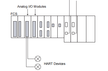
This document describes about I/O Modules with Built-in Barrier (for FIO) which can be installed in Zone 2 or
Division 2 and connected to devices located in Zone 0, 1, or Division 1.
These modules have galvanic isolation between the field interface and systems but they do not have isolation
between channels.
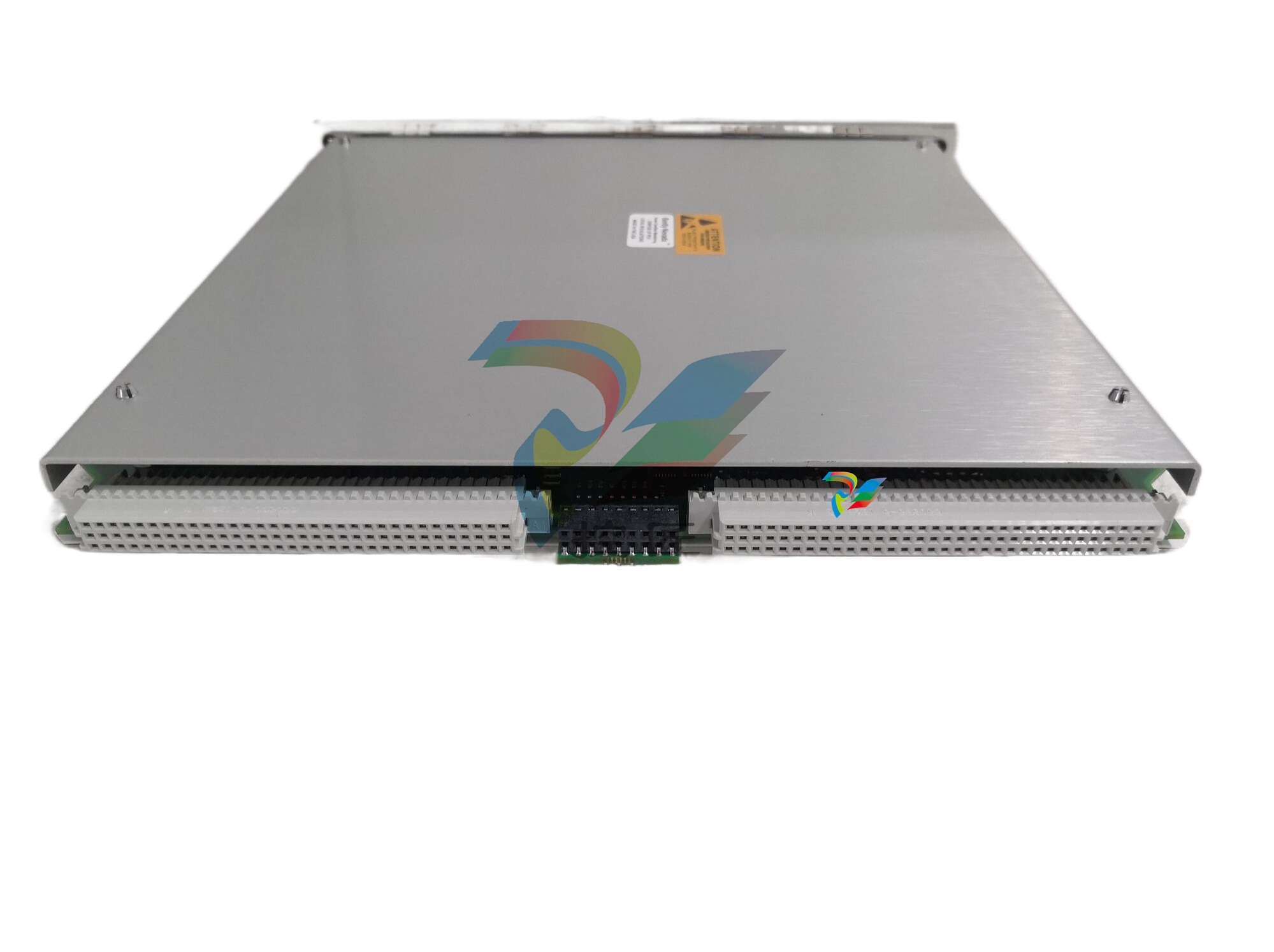
YOKOGAWA AFV30D-S41 I/O Modules with Built-in Barrier
These modules comply with ISA S71.04 class G3. and they can be located in the ambient temperature of -20 to 70
°C.
When connecting these modules to the intrinsically safe circuit, refer to documents “Explosion Protection” (TI
33Q01J30-01E) and “Explosion Protection of FIO Products” (IM 33K01J30-50E) for ATEX approval along with this
General Specifications (GS).
Follow the EC-type Examination Certificate or FM certification for details of the rules and regulations of installing
these modules in the intrinsically safe environment. It is especially important to follow the “Special Conditions”
stated in these certificates.
In case these I/O modules with built-in barriers are to comply with FM approval (FM3610), install them on the
following field control units (FCU) or ESB bus node units equipped with power supply modules of PW481-11.
PW482-11. or PW484-11.
Field Control Units: AFV30D-S4111. AFV30S-S3111. AFV30S-S4111
ESB Bus Node Units: ANB10D-41. ANB10S-31. ANB10S-41
ANB10D-43. ANB10S-33 , ANB10S-43
Optical ESB Bus Node Unit: ANB11D-23. ANB11D-43
ANB11S-13. ANB11S-23. ANB11S-33. ANB11S-43
Current Input Modules (Isolated)
Items Specifications
Model ASI133
Number of input channels 8. isolated
Input signal 4 to 20 mA
Allowable input current 22.5 mA
Withstanding voltage 1500 V AC
Input resistance Power ON For 2-wire: 400 Ω (I=20 mA) to 750 Ω (I=4 mA)
For 4-wire: 485 Ω (I=20 mA) to 925 Ω (I=4 mA)
Power OFF 1 MΩ or larger
Accuracy ±16 µA
Step response time 100 ms
Data update period 10 ms
Transmitter power supply 16 V DC or higher (output current limit: 20 mA)
Maximum normal mode input voltage applied to
the terminals by 4-wire transmitter 25 V
Drift due to ambient temperature change ±16 µA/10 °C
Maximum current consumption 150 mA (5 V DC), 450 mA (24 V DC)
Weight Approx. 0.30 kg
External connection Pressure clamp terminal (ATSA3□)
HART communication Available
Barrier type Isolated interface
Note: When short circuits occur in two or more channels in the field, all channels of the module fails for intrinsic safety.
l Current Output Modules (Isolated)
Items Specifications
Model ASI533
Number of output channels 8. isolated
Output signal 4 to 20 mA
Maximum output current 23 mA
Withstanding voltage 1500 V AC
Allowable load resistance 0 to 750 Ω at 20 mA, 0 to 600 Ω at 23 mA
Accuracy ±48 µA
Step response time 100 ms
Data update period 10 ms
Drift due to ambient temperature change ±16 µA/10 °C
Maximum current consumption 150 mA (5 V DC), 350 mA (24 V DC)
Weight Approx. 0.30 kg
External connection Pressure clamp terminal (ATSS3)
HART communication Available
Barrier type Isolated interface
Note: When short circuits occur in two or more channels in the field, all channels of the module fails for intrinsic safety
TC, mV Input/RTD/POT Input Modules (Isolated)
Items Specifications
Model AST143 (*1) (*2) ASR133 (*1)
Number of input channels 16. isolated 8. isolated
Input signal
TC: IEC 60584-1 (ITS-90)
Type B (*3), E, J, K, N, R, S, T
mV: -100 to 150 mV, -50 to 75 mV
RTD: 2.3 and 4-wire type
IEC 60751 (ITS-90): Pt50. Pt100. Pt200. Pt500. Pt1000
DIN 43760-1987: Ni100. Ni200
Minco: Ni120
POT: 3-wire type 0 to 10 kΩ
Switching input signal TC/mV can be set individually for CH1
to CH16. RTD/POT can be selected individually for CH1 to CH8.
Allowable input voltage ±5 V ±5 V
Withstanding voltage 1500 V AC 1500 V AC
Input resistance Power ON 1 MΩ or larger 1 MΩ or larger
Power OFF 1 MΩ or larger 1 MΩ or larger
Accuracy (at 23 °C) TC: ±40 µV
mV: ±80 µV
Pt50. Pt100. Ni100. Ni200. Ni120: ±150 mΩ
Pt200: ±300 mΩ
Pt500: ±600 mΩ
Pt1000: ±1.2 Ω
POT: ±2 Ω
Allowable total resistance of signal
source plus wiring 1000 Ω or less 50 Ω per load (*4)
Effect of allowable signal source
resistance (1000 Ω) ±20 µV –
Reference junction compensation
accuracy ±1 °C (*5) (*6) –
Measurement current – 150 µA
Temperature drift TC: ±125 µV/10 °C
mV: ±250 µV/10 °C
Pt50. Pt100. Ni100. Ni200. Ni120: ±325 mΩ/10 °C
Pt200: ±650 mΩ/10 °C
Pt500: ±1.3 Ω/10 °C
Pt1000: ±2.6 Ω/10 °C
POT: ±5.2 Ω/10 °C
Data update period 1 second or less 1 second or less
Burn-out All channels can be set together. Setting : Not available/available (UP/DOWN)
Maximum current consumption 150 mA (5 V DC), 80 mA (24 V DC) 150 mA (5 V DC), 60 mA (24 V DC)
Weight Approx. 0.30 kg Approx. 0.30 kg
External connection Pressure clamp terminal (ATST4) Pressure clamp terminal (ATSR3)
Barrier type Isolated interface Isolated interface
*1: In order to satisfy the EMC requirements in accordance with the IEC 61000. use the shielded cable. (Shielded multi-core
cable with one shield for all channel is sufficient.)
*2: Use a non-ground type thermocouple (TC) because AST143 is an isolated type module. By connecting a groun
| User name | Member Level | Quantity | Specification | Purchase Date |
|---|


-
 ABB VA-MC15-05 Controller Module
 -
 ABB VA-3180-10 Variable Speed Drive
 -
 ABB 72395-4-039123 excitation system power module
 -
 ALSTOM NRD108031 TRVC070999000 BOTTOM high-speed counting module
 -
 ALSTOM CMU 42015-115-00 Control Module
 -
 GE P40 Agile Series Intelligent Electronic Devices (IEDs)
 -
 ABB EasyLine series gas analyzer EL3020, EL3040
 -
 ABB 83SR04 module
 -
 ABB 216EA61b High Performance Industrial Control Module
 -
 ABB MB510 Program Card Interface
 -
 ABB LDGRB-01 3BSE013177R1 Stand-alone resolution module
 -
ABB ACH550-01 frequency converter
-
 ABB DTDX991A 61430001-UW servo controller
 -
 ABB 300 series NEMA rated full voltage controller
 -
 ABB DTCC901B High Performance Digital Temperature Controller
 -
 ABB 5SHX14H4502 Controller
 -
 ABB 3BSE013064R1 PU516 Engineering Board -PCI
 -
 ABB 5SHX10H6004 Control Signal Processing Module
 -
 ABB PPE091A101 medium voltage frequency converter
 -
ABB CONTROL UNIT SYN 5201A-Z,V277 3BHB006714R0277
-
 ABB 3BSE017235R1 PXAH 401 Operator unit
 -
 ABB Plantguard Safety Instrumented System
 -
 ABB AC 800M 6.0 Controller Hardware
 -
 ABB Panel 800 Version 6 Series Operator Panel
 -
 ABB System proS series enclosed starter
 -
 ABB Tmax T7 series molded case circuit breaker
 -
 ABB UK 500 series household distribution box
 -
 ABB contactors and overload relays
 -
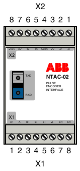 ABB NTAC-0x pulse encoder interface module
 -
 ABB electronic timer CT-APS.22
 -
 ABB Small, compact Thermostat KTO 011 / KTS 011
 -
 ABB medium voltage frequency converter ACS2000 4kV frame 1, 2, 3 spare parts
 -
ABB low-voltage AF contactor AF400... AF460
-
ABB KPM Sheet Break Detector - KB2
-
 ABB TP854 base plate
 -
 ABB AO845A Analog Output Module
 -
 ABB FS450R12KE3+AGDR-71C Integrated Circuit
 -
 ABB PNI800K01 Ability ™ Symphony ® Plus Hardware Selector
 -
 ABB REA 101 arc protection relay
 -
ABB 3BSC950193R1 TB850 CEX-Bus Terminator
-
 ABB BC810K02 Compact Product Kit Hardware
 -
 ABB DI810 digital input module
 -
 ABB Harmony Sequence of Events (SOE) system
 -
 ABB Tension Electronics PFEA111/112
 -
 ABB AI801 Analog Input Module
 -
 ABB AF C094 AE02 ARCnet Control Board
 -
 ABB TP830-1 PLC module
 -
 ABB CP430 Human Machine Interface (HMI) Installation and Operation
 -
 ABB 81EU01-E/R3210 Analog Signal Input Module
 -
 ABB Panel 800- PP836 5.1 Hardware and Installation
 -
ABB PM866AK01 Controller
-
ABB TK850V007 CEX Bus expansion cable Installation and configuration method
-
ABB AO801 Analog Output Module
-
ABB CI855 communication interface
-
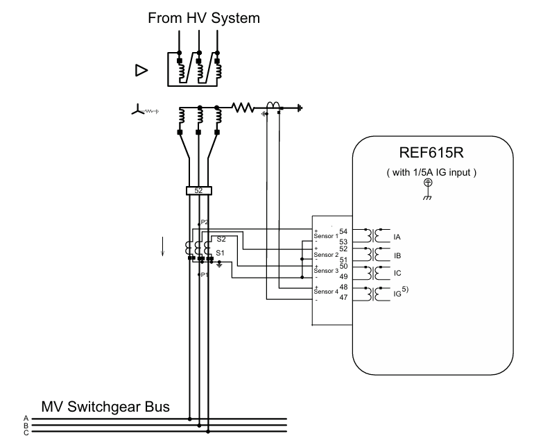 ABB REF615R feeder protection and control
 -
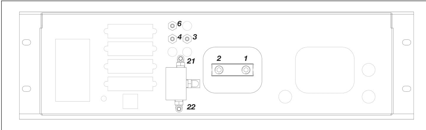 ABB EL3020 Model EasyLine Continuous Gas Analyzers
 -
 MOLEX SST-PB3-VME-1 and SST-PB3-VME-2 Hardware Reference Guide
 -
 Eaton XVH300 MICRO PANEL
 -
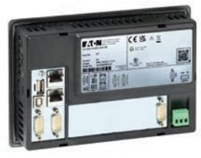 Eaton XV-303/XV-313 multi touch display
 -
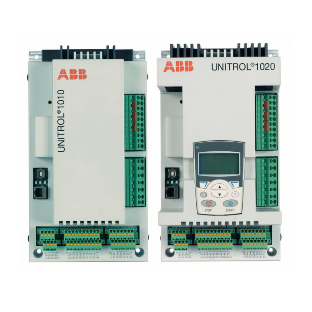 ABB Panel 800 Version 6 Operator Panel
 -
ABB 1SVR011718R2500 Analog Signal Converter
-
ABB BC810K02 CEX Bus Interconnection Unit Kit
-
 ABB RELION ® 615 series REU615 voltage protection and control relay
 -
ABB Symphony Harmony/INFI 90 DCS Remote I/O Module Upgrade Kit
-
 ABB REM610C55HCNN02 motor protection relay
 -
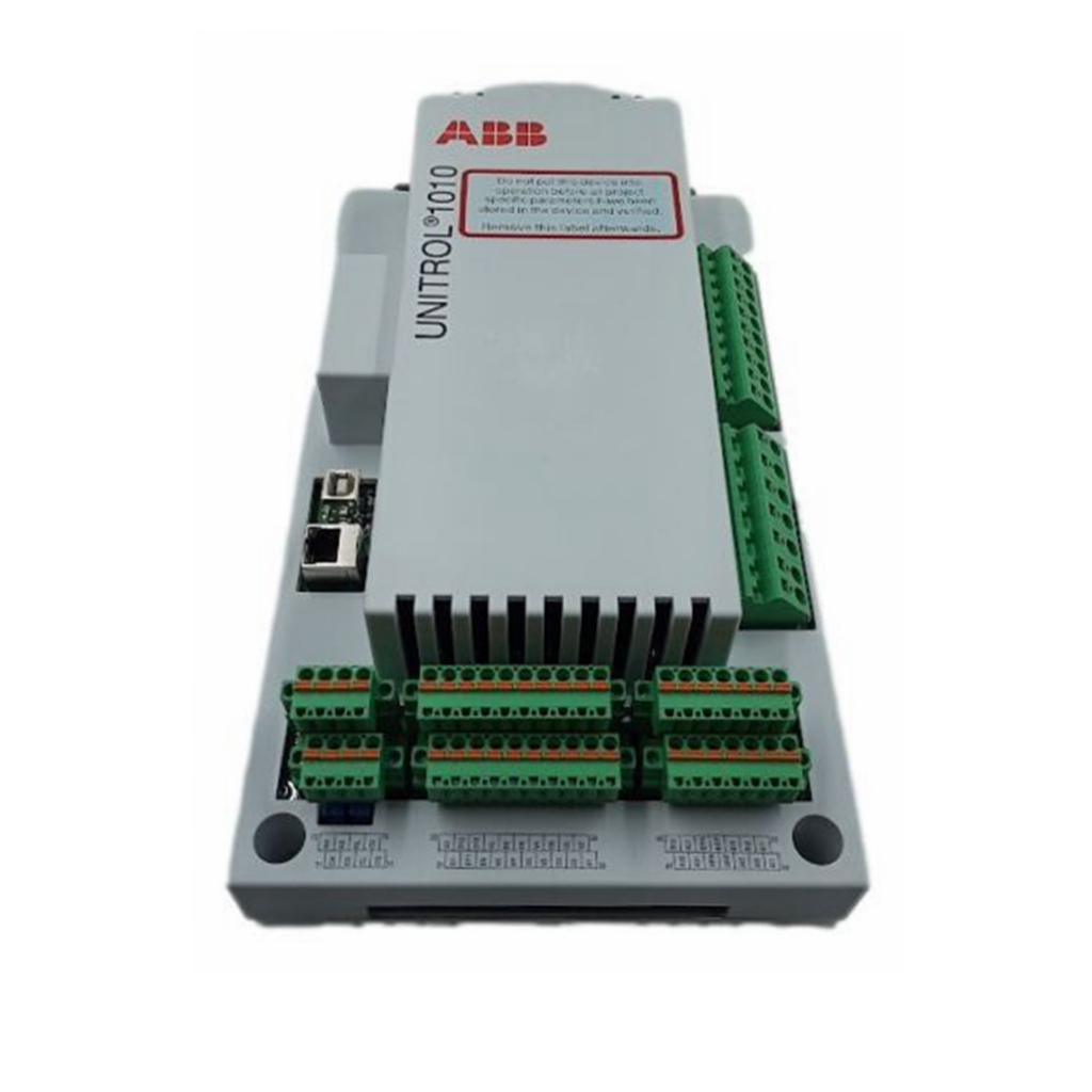 ABB TU810V1 Compact Terminal Unit
 -
 ABB REF 541, REF 543, and REF 545 feeder terminals
 -
ABB UNITOL 1000 series automatic voltage regulator
-
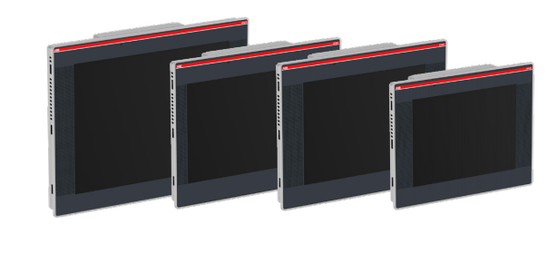 ABB PCD235C101 3BHE057901R0101 AC800pec Excitation High Performance Control System
 -
ABB GFD233 3BHE022294R0102 Redundant System Control Module
-
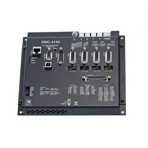 Galil DMC-40x0 series motion controller
 -
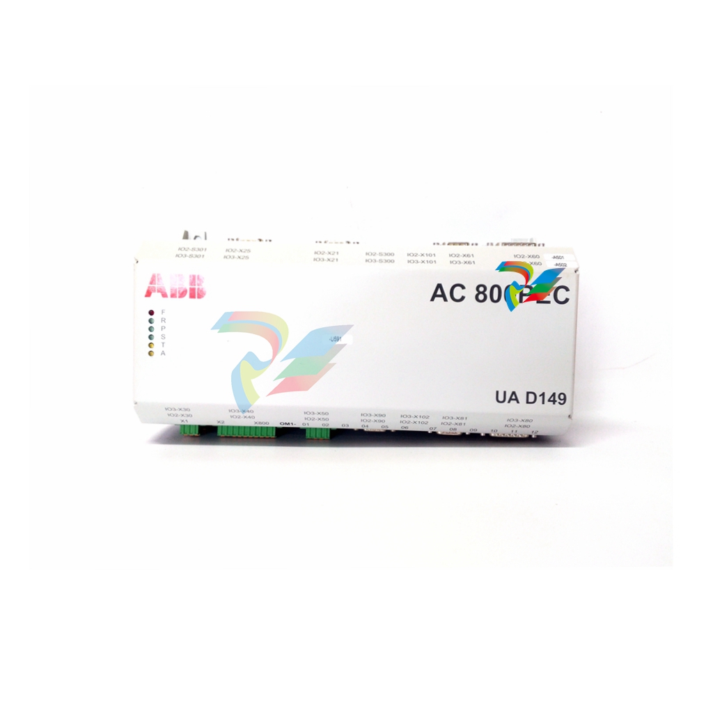 ABB AO2040-CU Ex Central Unit
 -
 ABB REF615 feeder protection relay
 -
 ABB INSUMMCU2 MCU2A02V24 motor control unit
 -
ABB REF 542plus multifunctional protection and switchgear control unit
-
 ABB PP886 Compact Product Suite hardware selector
 -
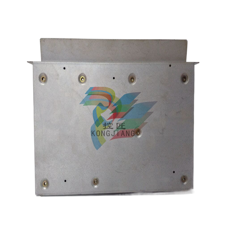 ABB AC500 V3 PLC Enhanced connectivity and performance
 -
ABB SYNCHROTACT ® 5 Synchronous and Parallel Devices
-
 ABB SUE 3000 high-speed switching device
 -
ABB REF542plus multifunctional protection and switchgear control unit
-
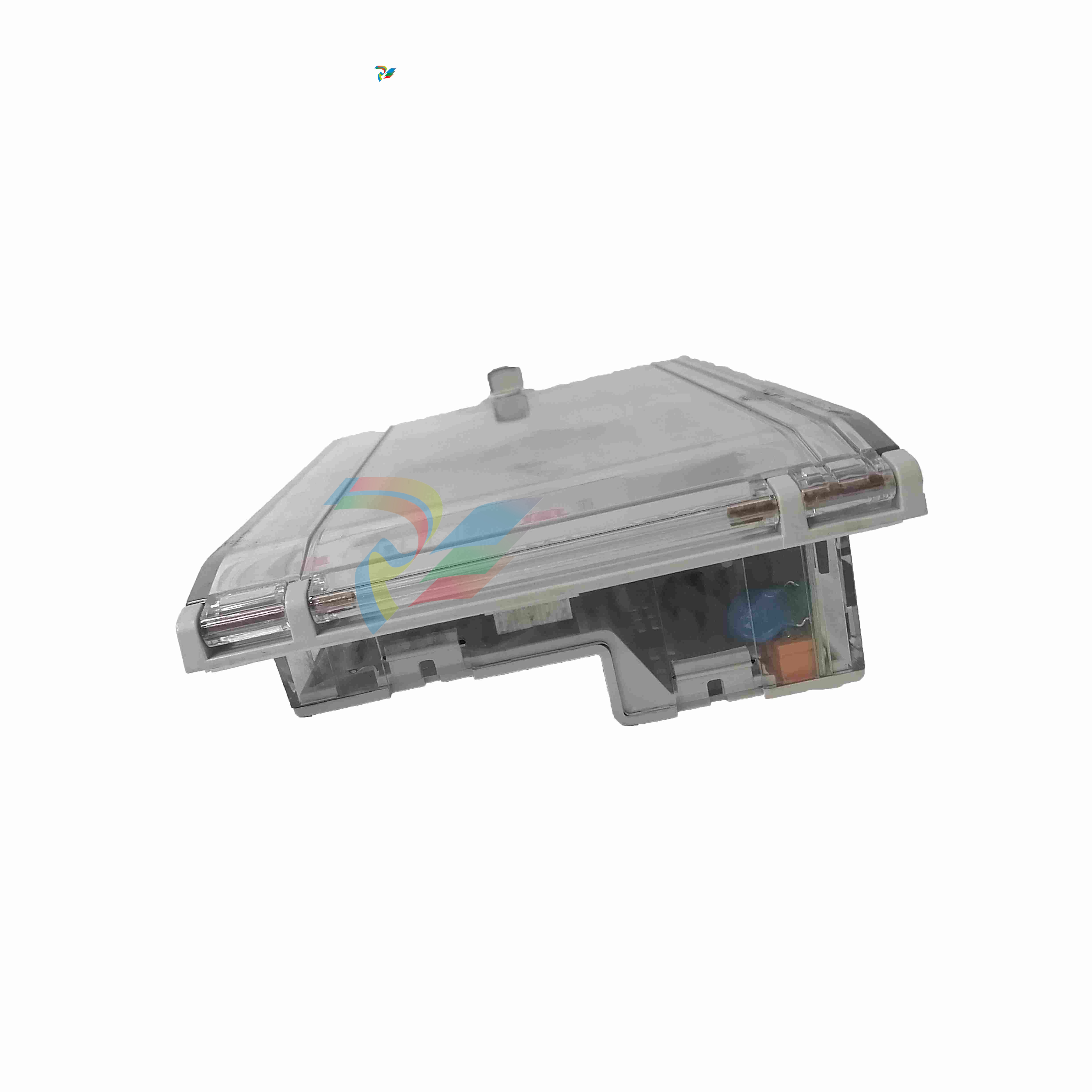 ABB Relion ® 615 series REF615 feeder protection and control device
 -
 Bentley 3500/45 Position Monitor
 -
Bentley 3500/42 Proximitors ®/ Earthquake monitoring module
-
ABB molded case circuit breaker
-
 ABB MVME162 Embedded Controller
 -
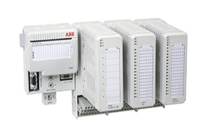 ABB TU810V1 System 800xA hardware selector
 -
 ABB SPAJ 140 C overcurrent and ground fault relay
 -
ABB AC 800PEC High Performance Control System
-
ABB REF601 and REJ601 relays
-
 ALSTOM RPH3/PS125b Controlled Switching Device,CT1VT220/TCR
 -
ABB V-Contact VSC Medium voltage vacuum contactors
-
ABB 3BHE004385R0001 UNS 0884a, V1:Current Sensor 2000A
-
ABB UAD206A101 Programmable Logic Controller
-
 ABB ACS800-04/U4 driver module
 -
ABB UAD149A0011 3BHE014135R0011 Controller Module
-
 ABB BSM series AC servo motor
 -
 ALSTOM DFI-150-0003- Limelight Diagnostic Board
 -
 ABB GCC960C102 motor driver
 -
 ABB INDUSTRIALDRIVES UCU-22, UCU-23 andUCU-24control units
 -
ABB XDD501A101 Bus Terminal Module
-
 ABB S800 I/O DTM 5.3 module
 -
 ALSTOM N897164611M High Performance Control Module
 -
 ALSTOM N897164610L Pulse Output Module
 -
 ALSTOM N70032702L High Performance Control Module
 -
 ALSTOM MVAJ1L1GB0771B Auxiliary Transmission Relay
 -
 GE 239 MOTOR PROTECTION RELAY
 -
ALSTOM ADVANCED MICRO CONTROLLER 2
-
 Honeywell HC900 Process and Safety Controller
 -
ABB ControlMaster CM10 Universal Process Controller
-
ABB dual power conversion switch
-
 ABB RET 541/543/545 Transformer Terminal Device
 -
 ABB Relion ® RET620 Transformer Protection and Control Device
 -
 ABB Relion ® REU615 Voltage Protection and Control Device
 -
 ABB Relion ® REU615 Voltage Protection and Control Device
 -
 ABB REX615 Protection and Control Relay Products
 -
ABB PGC2000 series E2 process gas chromatograph
-
 ABB PROCOLOR P 88QT03 bus coupling module
 -
 Honeywell WEB-8000 Controller
 -
 ABB Protection Relay REX 521
 -
ABB 5SGY3545L0020 Controller Module
-
ABB 5SGY3545L0017 module tension controller
-
ABB 5SGY3545L003 IGCT control module
-
ABB SNAT609TAI 5761789-6H Industrial I/O Interface Card
-
ABB SNAT602TAC circuit board
-
ABB SNAT603 CNT Control Board
-
ABB SNAT634PAC pulse amplifier module
-
 ABB RK682011-BA RL0B 100 standard unit module
 -
 ABB PP846A 3BSE042238R2 Industrial Control Panel

