

K-WANG
+086-15305925923
Service expert in industrial control field!


Product
Article
NameDescriptionContent
Adequate Inventory, Timely Service
pursuit of excellence


Ship control system
Equipment control system
Power monitoring system
Brand
Product parameters
- Telephone:+86-15305925923
- contacts:Mr.Wang
- Email:wang@kongjiangauto.com
Description
The 2 Amp Relay Output module for the Series 90-30 Programmable Logic Controller
provides 16 normally-open relay circuits for controlling output loads provided by the user. The
output switching capacity of each output is 2 amps. The output points are arranged in four
groups of four points each.
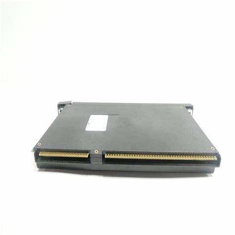
GE IC693MDL940 Relay Output, N.O., 2 Amp - 16 Point
Relay Output, N.O., 2 Amp - 16 PointIC693MDL940
The 2 Amp Relay Output module for the Series 90-30 Programmable Logic Controller
provides 16 normally-open relay circuits for controlling output loads provided by the user. The
output switching capacity of each output is 2 amps. The output points are arranged in four
groups of four points each. Each group has a common power output terminal. The relay
outputs can control a wide range of user-supplied load devices, such as: motor starters,
solenoids, and indicators. Power for the internal relay circuits is provided by the +24 volt DC
bus on the backplane. The user must supply the AC or DC power to operate field devices.
There are no fuses on this module.
LED indicators which provide the ON/OFF status of each point are located at the top of the
module. The LEDs are arranged in two horizontal rows with eight green LEDs in each row; the top
row labeled A1 through 8 (points 1 through 8) and the bottom row labeled B1 through 8 (points 9
through 16). An insert goes between the inside and outside surface of the hinged door. The surface
towards the inside of the module (when the hinged door is closed) has circuit wiring information,
and circuit identification information can be recorded on the outside surface. The outside left edge
of the insert is color-coded red to indicate a high-voltage module. This module can be installed in
any I/O slot of a 5 or 10-slot baseplate in a Series 90-30 PLC system.
Table 7-19. Specifications for IC693MDL940
Rated Voltage 24 volts DC, 120/240 volts AC (nominal – see the following
table for exceptions)
Operating Voltage 5 to 30 volts DC
5 to 250 volts AC, 50/60 Hz
Outputs per Module 16 (four groups of four outputs each)
Isolation 1500 volts between field side and logic side
500 volts between groups
Maximum Load 2 amps pilot duty maximum per output
4 amps maximum per common
Minimum Load 10 mA
Maximum Inrush 5 amps
On Response Time 15 ms maximum
Off Response Time 15 ms maximum
Int. Power Consumption 7 mA (all outputs on) from 5 volt bus on backplane
135 mA (all outputs on) from relay 24V bus on backplane
Refer to Appendix B for product standards and general specifications.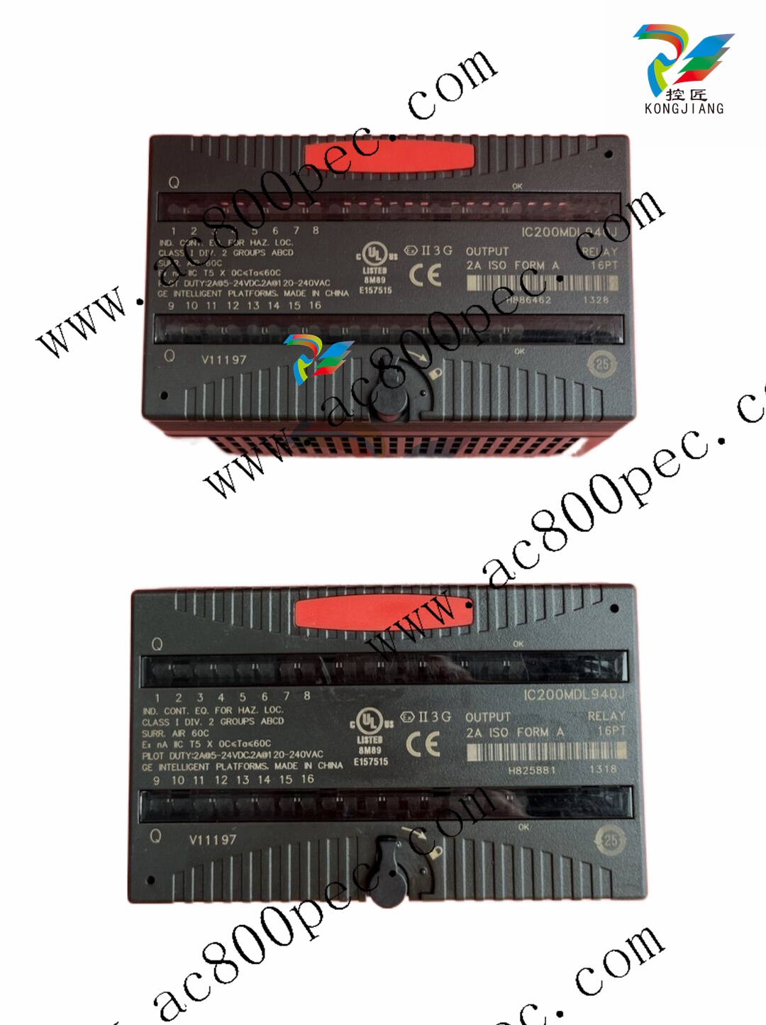
IC693MDL940 Output Module Field Wiring Information
The following figure provides wiring information for connecting user supplied load devices
and power source to the 2 amp N.O. Relay output module.
Table 7-20. Load Current Limitations for IC693MDL940
Operating
Maximum Current
for Load Type Typical Contact Life
Voltage Resistive Lamp or Solenoid (Number of Operations)
24 to 120 VAC 2 amps 1 amp 300,000
24 to 120 VAC 1 amp .5 amps 500,000
24 to 120 VAC .1 amps .05 amps 1,000,000
240 VAC 2 amps 1 amp 150,000
240 VAC 1 amp .5 amps 200,000
240 VAC .1 amps .05 amps 500,000
24 VDC - 2 amps 100,000
24 VDC 2 amps 1 amp 300,000
24 VDC 1 amp .5 amps 500,000
24 VDC .1 amps .05 amps 1,000,000
125 VDC .2 amps .1 amps 300,000
Assumes a 7 ms time constant
Relay contact life, when switching inductive loads, will approach resistive load contact life if
suppression circuits are used. The following figures are examples of typical suppression
circuits for AC and DC loads. The 1A, 200V diode shown in the DC load suppression circuit is
an industry standard 1N4935. The resistor and capacitor shown for AC load suppression are
standard components, available from most electronics distributors.
DC LOADS
SERIES
90-30
RELAY
OUTPUT
COM
DC SUPPLY
1A, 200V
a45151A
Load Coil
Figure 7-36. Load Suppression Examples for IC693MDL940 Output Module
Purchase history
| User name | Member Level | Quantity | Specification | Purchase Date |
|---|
Total 0 Record
Customer Reviews
Satisfaction :
5 Stars
No evaluation information


-
 ABB medium voltage frequency converter ACS2000 4kV frame 1, 2, 3 spare parts
 -
 ABB low-voltage AF contactor AF400... AF460
 -
ABB KPM Sheet Break Detector - KB2
-
 ABB TP854 base plate
 -
 ABB AO845A Analog Output Module
 -
 ABB FS450R12KE3+AGDR-71C Integrated Circuit
 -
 ABB PNI800K01 Ability ™ Symphony ® Plus Hardware Selector
 -
 ABB REA 101 arc protection relay
 -
 ABB 3BSC950193R1 TB850 CEX-Bus Terminator
 -
 ABB BC810K02 Compact Product Kit Hardware
 -
 ABB DI810 digital input module
 -
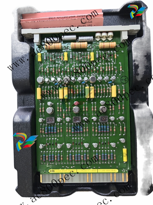 ABB Harmony Sequence of Events (SOE) system
 -
 ABB Tension Electronics PFEA111/112
 -
 ABB AI801 Analog Input Module
 -
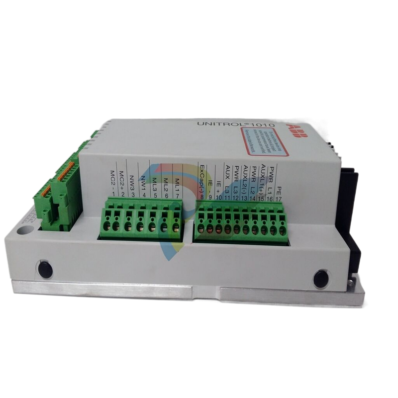 ABB AF C094 AE02 ARCnet Control Board
 -
 ABB TP830-1 PLC module
 -
 ABB CP430 Human Machine Interface (HMI) Installation and Operation
 -
 ABB 81EU01-E/R3210 Analog Signal Input Module
 -
 ABB Panel 800- PP836 5.1 Hardware and Installation
 -
ABB PM866AK01 Controller
-
 ABB TK850V007 CEX Bus expansion cable Installation and configuration method
 -
ABB AO801 Analog Output Module
-
ABB CI855 communication interface
-
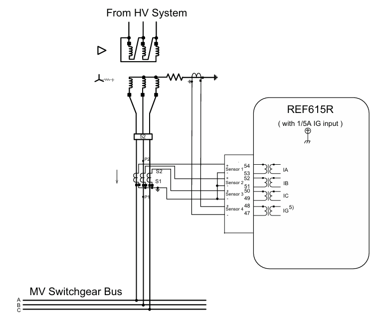 ABB REF615R feeder protection and control
 -
 ABB EL3020 Model EasyLine Continuous Gas Analyzers
 -
 MOLEX SST-PB3-VME-1 and SST-PB3-VME-2 Hardware Reference Guide
 -
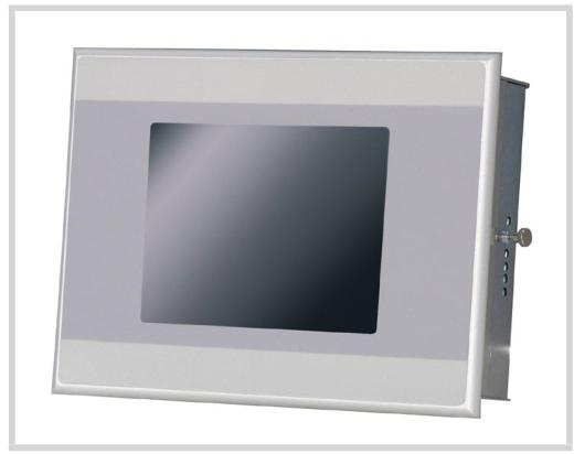 Eaton XVH300 MICRO PANEL
 -
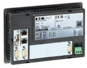 Eaton XV-303/XV-313 multi touch display
 -
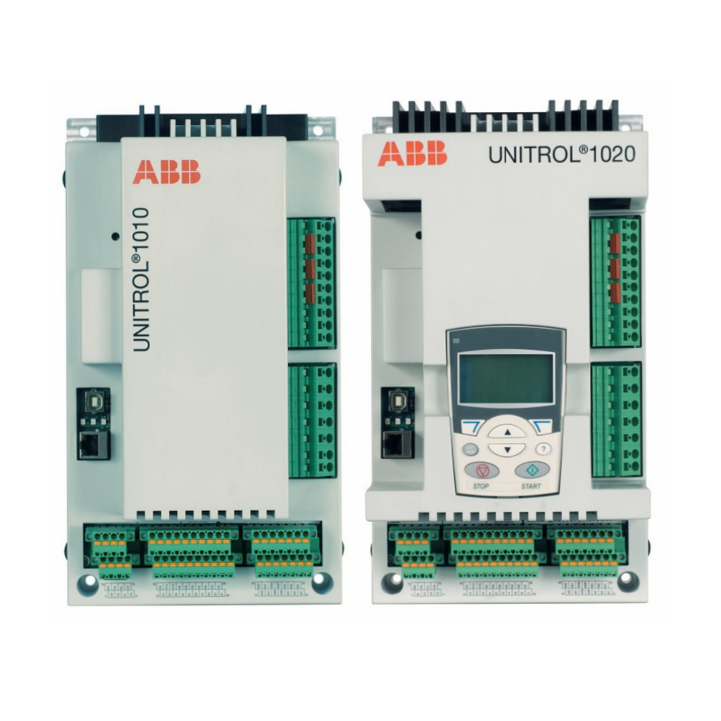 ABB Panel 800 Version 6 Operator Panel
 -
 ABB 1SVR011718R2500 Analog Signal Converter
 -
 ABB BC810K02 CEX Bus Interconnection Unit Kit
 -
 ABB RELION ® 615 series REU615 voltage protection and control relay
 -
 ABB Symphony Harmony/INFI 90 DCS Remote I/O Module Upgrade Kit
 -
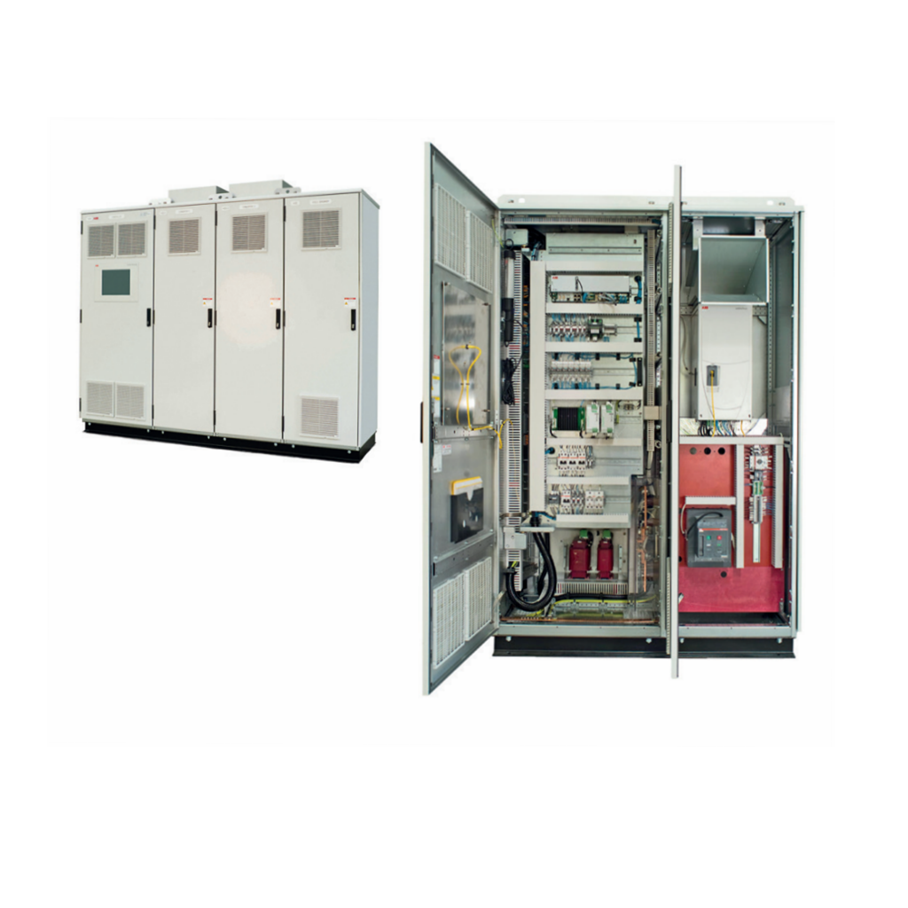 ABB REM610C55HCNN02 motor protection relay
 -
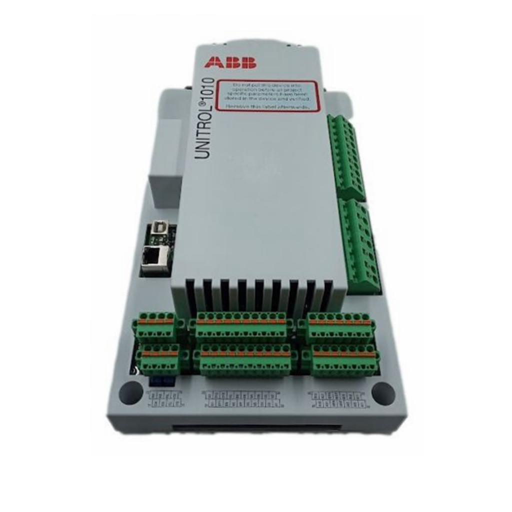 ABB TU810V1 Compact Terminal Unit
 -
 ABB REF 541, REF 543, and REF 545 feeder terminals
 -
ABB UNITOL 1000 series automatic voltage regulator
-
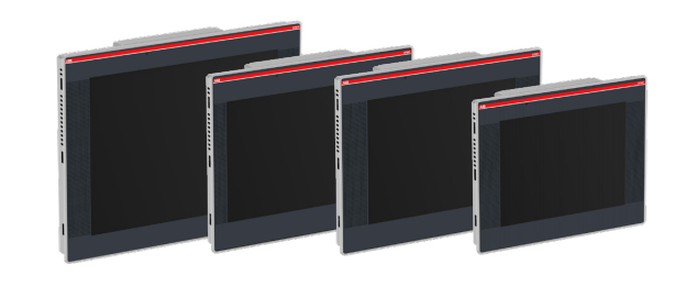 ABB PCD235C101 3BHE057901R0101 AC800pec Excitation High Performance Control System
 -
ABB GFD233 3BHE022294R0102 Redundant System Control Module
-
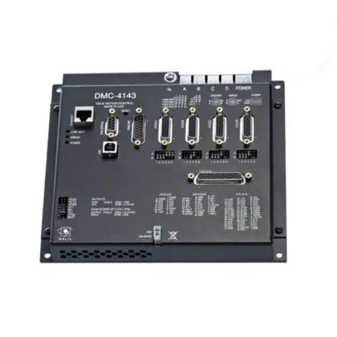 Galil DMC-40x0 series motion controller
 -
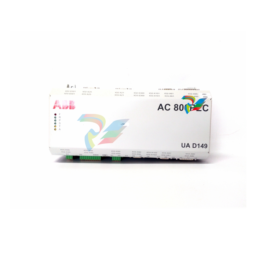 ABB AO2040-CU Ex Central Unit
 -
 ABB REF615 feeder protection relay
 -
 ABB INSUMMCU2 MCU2A02V24 motor control unit
 -
 ABB REF 542plus multifunctional protection and switchgear control unit
 -
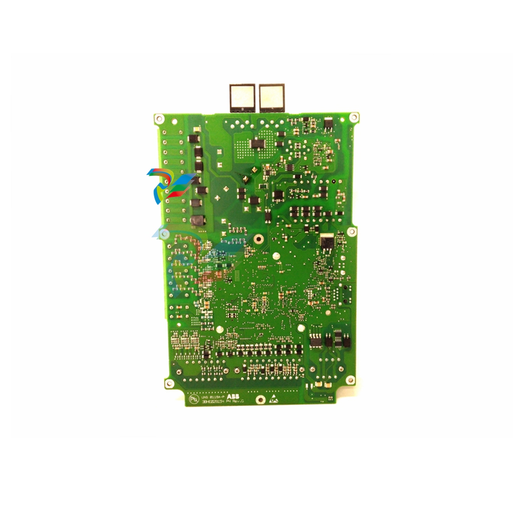 ABB PP886 Compact Product Suite hardware selector
 -
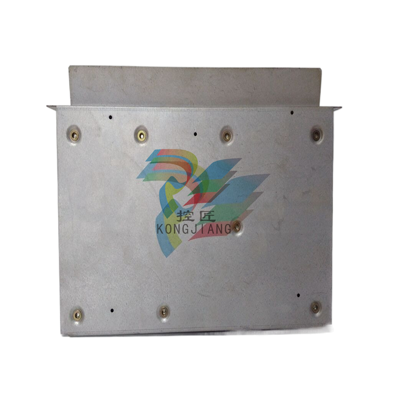 ABB AC500 V3 PLC Enhanced connectivity and performance
 -
ABB SYNCHROTACT ® 5 Synchronous and Parallel Devices
-
 ABB SUE 3000 high-speed switching device
 -
 ABB REF542plus multifunctional protection and switchgear control unit
 -
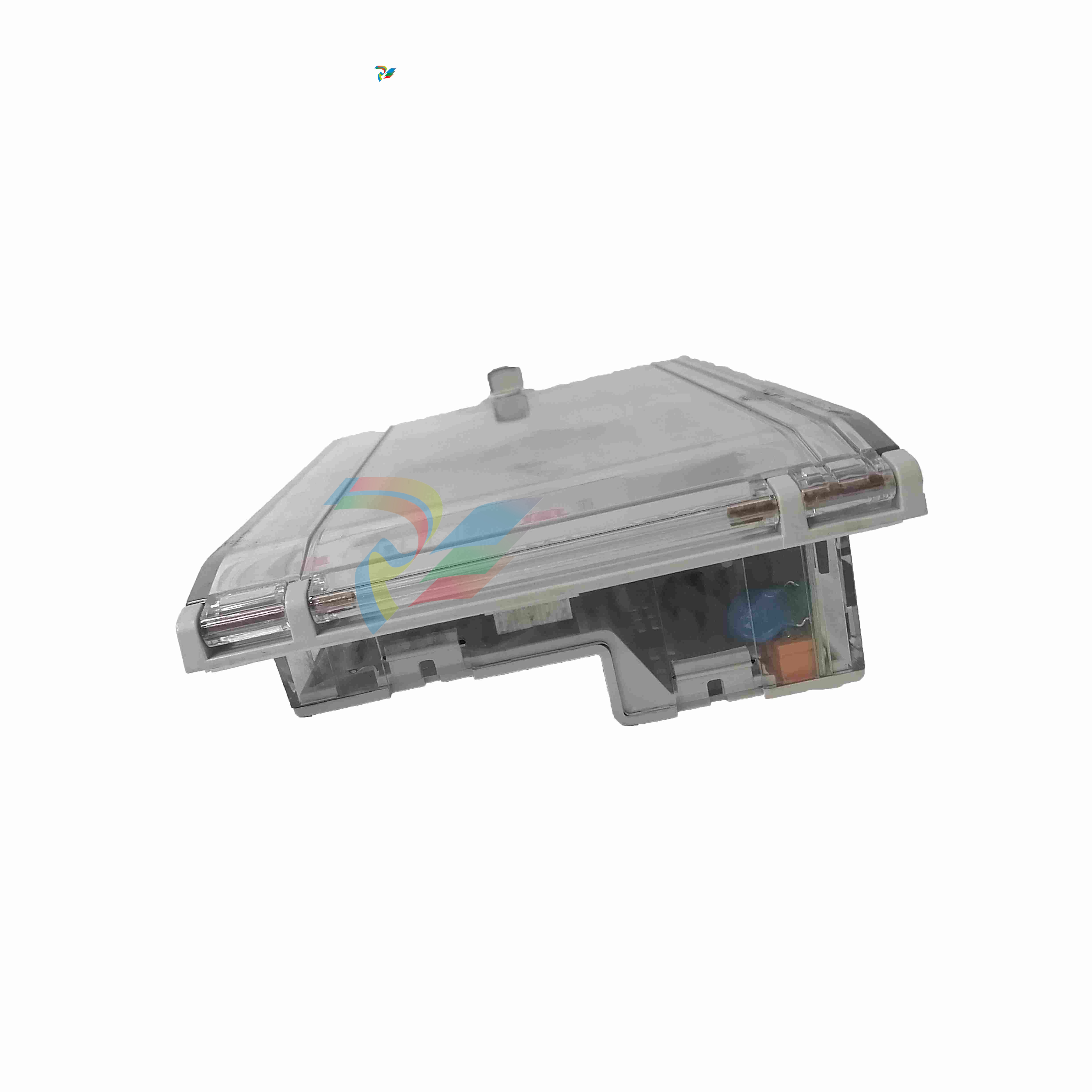 ABB Relion ® 615 series REF615 feeder protection and control device
 -
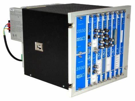
 Bentley 3500/45 Position Monitor
 -
Bentley 3500/42 Proximitors ®/ Earthquake monitoring module
-
 ABB molded case circuit breaker
 -
 ABB MVME162 Embedded Controller
 -
 ABB TU810V1 System 800xA hardware selector
 -
 ABB SPAJ 140 C overcurrent and ground fault relay
 -
ABB AC 800PEC High Performance Control System
-
ABB REF601 and REJ601 relays
-
 ALSTOM RPH3/PS125b Controlled Switching Device,CT1VT220/TCR
 -
ABB V-Contact VSC Medium voltage vacuum contactors
-
ABB 3BHE004385R0001 UNS 0884a, V1:Current Sensor 2000A
-
ABB UAD206A101 Programmable Logic Controller
-
 ABB ACS800-04/U4 driver module
 -
 ABB UAD149A0011 3BHE014135R0011 Controller Module
 -
 ABB BSM series AC servo motor
 -
 ALSTOM DFI-150-0003- Limelight Diagnostic Board
 -
 ABB GCC960C102 motor driver
 -
 ABB INDUSTRIALDRIVES UCU-22, UCU-23 andUCU-24control units
 -
ABB XDD501A101 Bus Terminal Module
-
 ABB S800 I/O DTM 5.3 module
 -
 ALSTOM N897164611M High Performance Control Module
 -
 ALSTOM N897164610L Pulse Output Module
 -
 ALSTOM N70032702L High Performance Control Module
 -
 ALSTOM MVAJ1L1GB0771B Auxiliary Transmission Relay
 -
 GE 239 MOTOR PROTECTION RELAY
 -
 ALSTOM ADVANCED MICRO CONTROLLER 2
 -
 Honeywell HC900 Process and Safety Controller
 -
ABB ControlMaster CM10 Universal Process Controller
-
ABB dual power conversion switch
-
 ABB RET 541/543/545 Transformer Terminal Device
 -
 ABB Relion ® RET620 Transformer Protection and Control Device
 -
 ABB Relion ® REU615 Voltage Protection and Control Device
 -
 ABB Relion ® REU615 Voltage Protection and Control Device
 -
 ABB REX615 Protection and Control Relay Products
 -
ABB PGC2000 series E2 process gas chromatograph
-
 ABB PROCOLOR P 88QT03 bus coupling module
 -
 Honeywell WEB-8000 Controller
 -
 ABB Protection Relay REX 521
 -
 ABB 5SGY3545L0020 Controller Module
 -
ABB 5SGY3545L0017 module tension controller
-
ABB 5SGY3545L003 IGCT control module
-
ABB SNAT609TAI 5761789-6H Industrial I/O Interface Card
-
ABB SNAT602TAC circuit board
-
ABB SNAT603 CNT Control Board
-
ABB SNAT634PAC pulse amplifier module
-
 ABB RK682011-BA RL0B 100 standard unit module
 -
 ABB PP846A 3BSE042238R2 Industrial Control Panel
 -
 ABB ZMU-02 inverter memory card
 -
ABB 3BHE014135R0011 UAD149A0011 DCS POSITIONING CONTROL MODULE
-
ABB 3BHE014135R0011 UAD149 A00-0-11 I/O module
-
 ABB MEASUREMENT & ANALYTICS Web Tension Systems with Tension Electronics PFEA113
 -
ABB GDD471A001 2UBA0022R0001 motor control module
-
ABB UCD224A103 high-performance control module
-
 ABB PDD205A0121 control module
 -
ABB PDD205A1121 3BHE02535R1211 processor module
-
ABB DSDX453 Digital Input/Output Module
-
ABB DSPC454 controller module
-
 Woodward ESDR4 Current Differential Protection Relay
 -
 Siemens SIJECT CI16iP StepB 6AТ1131-6DF21-0AB0 Compact Control
 -
 EtherNet/IP™ to Remote I/O or DH+ Gateway AN-X2-AB-DHRIO
 -
ABB 81EU01-E/R3210 Analog Signal Input Module
-
 ABB TK457V050 Industrial Temperature Controller
 -
 ABB DSRF197K01 Control Module
 -
 ABB TK802F SD802F/SD812F power cord
 -
ABB 3BHE03930R0101 I/O module
-
ABB 3BHB0040277R0101 GVC700AE01 thyristor module
-
 ABB 3BHB003154R0101 5SXE05-0156 IGCT module
 -
 RELIANCE INSPECTOR VCIB-06 Advanced Industrial Visual Display
 -
ABB AO2000-LS25 Laser analyzer
-
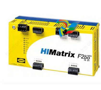 HIMA F8650X Central module
 -
ABB PM864AK01 Classic System 800xA hardware selector
-
ABB 3BSE048845R1 CI868K01 IEC 61850 Interface
-
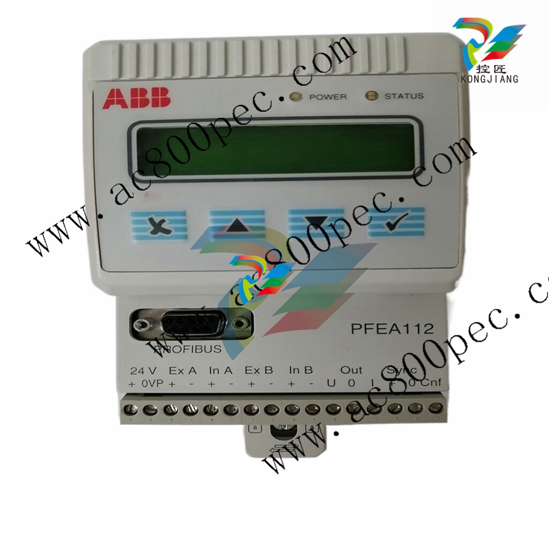 ABB 5SHY35L4520 Asymmetric Integrated Gate Converter Thyristor
 -
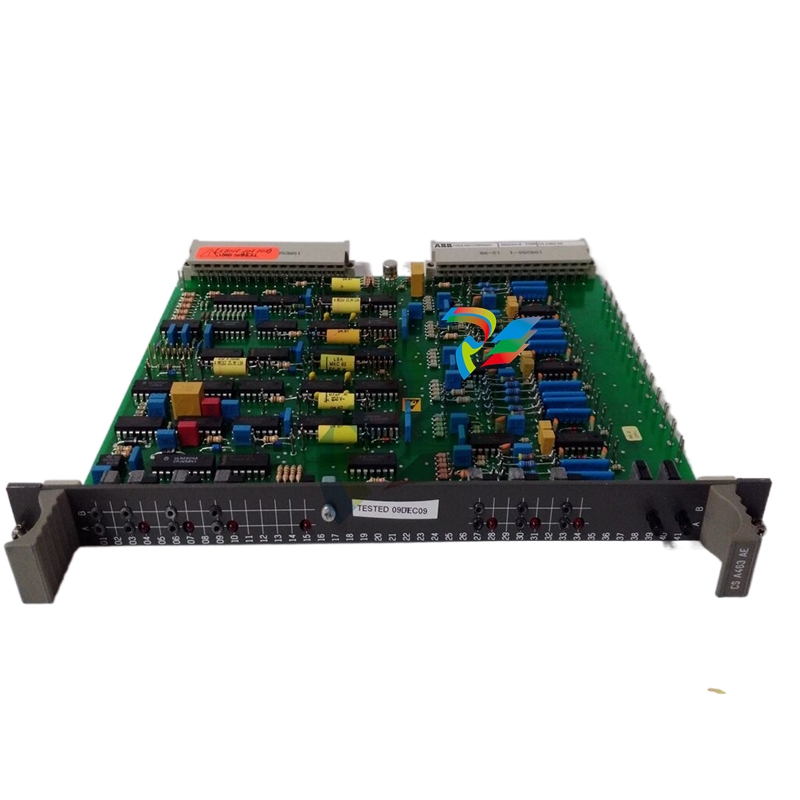 ABB UNS0119A-P V101 3BHE029153R0101 processor module
 -
 Xycom 99212A-001 PC board
 -
 Xycom 144365-001 motherboard
 -
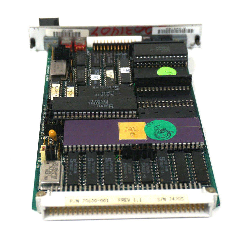
 XYCOM 70400-001 T3065-4 XVME-400 Board
 -
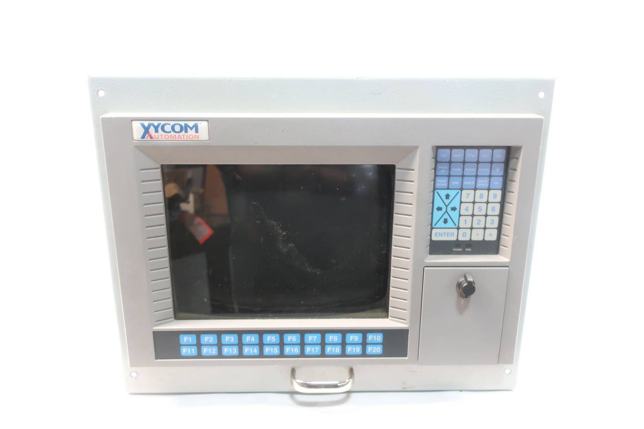 Xycom Automation # 9450-2480016010000 Interface Monitor Model

