
K-WANG
+086-15305925923
Service expert in industrial control field!


Product
Article
NameDescriptionContent
Adequate Inventory, Timely Service
pursuit of excellence


Ship control system
Equipment control system
Power monitoring system
Brand
Product parameters
- Telephone:+86-15305925923
- contacts:Mr.Wang
- Email:wang@kongjiangauto.com
Description
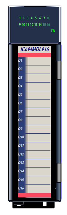
The 4 Amp 16 Point Relay Output module provides 16 Form A relays for controlling
output loads. The maximum output switching capacity of each circuit is 4 Amps. Each
output point is isolated from the other points, and each point has a separate common
power output terminal. Outputs provide a high degree of noise immunity, minimizing
the need to add external snubbers. The relay outputs can control a wide range of
output devices, such as: motor starters, solenoids, and indicators. The user must
supply the AC or DC power to operate the field devices.
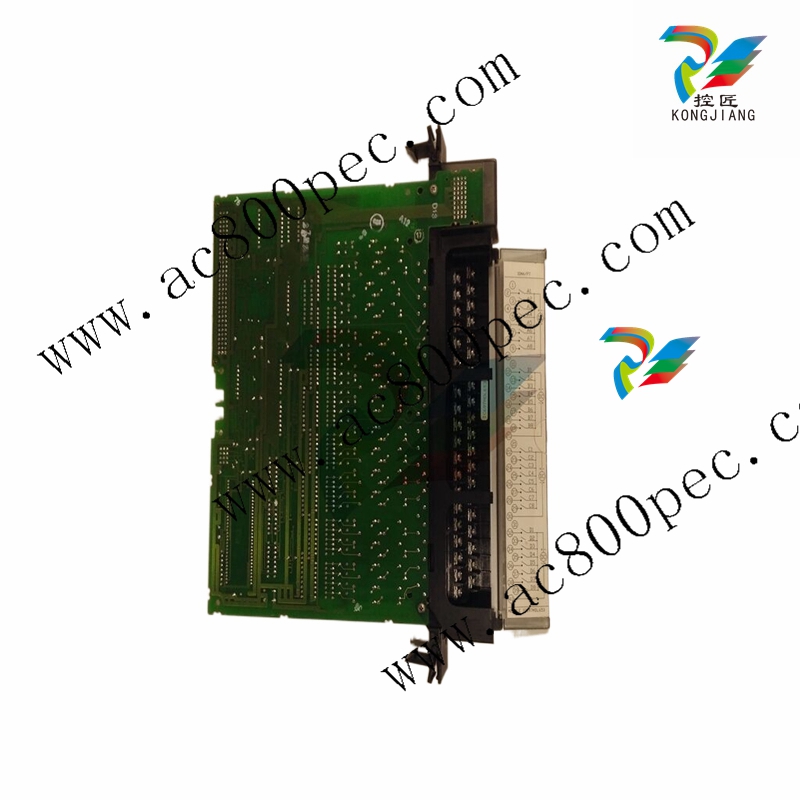
GE IC694MDL916 Output Module, Isolated Relay
The 4 Amp 16 Point Relay Output module provides 16 Form A relays for controlling
output loads. The maximum output switching capacity of each circuit is 4 Amps. Each
output point is isolated from the other points, and each point has a separate common
power output terminal. Outputs provide a high degree of noise immunity, minimizing
the need to add external snubbers. The relay outputs can control a wide range of
output devices, such as: motor starters, solenoids, and indicators. The user must
supply the AC or DC power to operate the field devices.
This module is available as a PACSystems RX3i module (catalog number
IC694MDL916), illustrated at left, or as a Series 90-30 PLC module (catalog number
IC693MDL916). The RX3i version is only compatible with a PACSystems RX3i CPU.
The Series 90-30 version can be installed in any I/O slot in a PACSystems RX3i or
Series 90-30 PLC. See the next page for details of specific CPU version requirements.
Module MDL916 can be used with a Box-style (IC694TBB032), Extended Box-style
(IC694TBB132), Spring-style (IC694TBS032), or Extended Spring-style
(IC694TBS132) Terminal Block. Extended terminal blocks provide the extra shroud
depth typically needed for shielded wires. See the PACSystems RX3i System Manual,
GFK-2314 revision B or later for more information about terminal blocks. Terminal
Blocks are ordered separately.
A DIP switch on back of the module is used to select the outputs’ default mode: Force
Off or Hold Last State. The module must be removed from the backplane to set this
switch.
Individually-numbered LEDs indicate the ON/OFF state of each output. The red/green
TB LED is green when the module’s removable terminal block is locked in place. It is
red when the terminal block is not locked.
Module IC694MDL916 reports Addition of Terminal Block, Loss of Terminal Block,
Hold Last State Configuration Mismatch, and Module Over Temp messages to the
RX3i CPU. Module IC693MDL916 does not report diagnostic status to the CPU.
The red bands on the door card show that MDL916 is a high-voltage module.
Release Information
Release History
Release Comments
IC693MDL916-AA, IC694MDL916-AA Initial Release
Functional Compatibility
Compatible CPU Versions
Module Configuration Software PACSystems
RX3i Series 90-30
IC693MDL916 CPU350 - 10.60, CPU352 - 10.50,
CPU364 – 10.60, CPU374 - 11.03
IC694MDL916
Proficy Machine Edition
version 5.5,
Service Pack 2 or later
Firmware version
3.81
Not compatible
Installation in Hazardous Locations
• EQUIPMENT LABELED WITH REFERENCE TO CLASS I, GROUPS A, B, C & D, DIV. 2 HAZARDOUS
LOCATIONS IS SUITABLE FOR USE IN CLASS I, DIVISION 2, GROUPS A, B, C, D OR NON-HAZARDOUS
LOCATIONS ONLY
• WARNING - EXPLOSION HAZARD - SUBSTITUTION OF COMPONENTS MAY IMPAIR SUITABILITY FOR
CLASS I, DIVISION 2;
• WARNING - EXPLOSION HAZARD - WHEN IN HAZARDOUS LOCATIONS, TURN OFF POWER BEFORE
REPLACING OR WIRING MODULES; AND
• WARNING - EXPLOSION HAZARD - DO NOT CONNECT OR DISCONNECT EQUIPMENT UNLESS POWER
HAS BEEN SWITCHED OFF OR THE AREA IS KNOWN TO BE NONHAZARDOUS.
Specifications
Refer to the PACSystems RX3i System Manual, GFK-2314, for product standards and general specifications.
Outputs per Module 16 isolated Form A relay outputs
External Power Supply 0 – 125VDC (5/24/125 VDC nominal)
0 – 250VAC (47 to 63 Hz), 120-240VAC nominal
Isolation
Field to Backplane and
to Frame Ground,
Group to Group
250 VAC continuous; 1500 VAC for 1 minute.
Power Consumption 300mA at 5VDC from backplane maximum (all outputs ON)
Thermal Derating See next page
Output Characteristics
Output Voltage 5 – 125VDC (5/24/125 VDC nominal)
5 – 250VAC (47 to 63 Hz), 120-240VAC nominal
Output Current 10mA per point minimum
4A for 5-250VAC maximum (resistive or general purpose)
4A for 5-30VDC maximum (resistive)
200mA for 125VDC (maximum resistive)
2A pilot duty per output (5 to 30VDC, 5 to 250VAC)
2A lamp load per output (5 to 30VDC, 5 to 250VAC)
Output Voltage Drop 0.3VDC maximum
Output Leakage Current Not Applicable (open contact)
Response Times (On/Off) 10ms maximum (At nominal voltage excluding contact bounce)
Switching Frequency 20 cycles per minute maximum
Protection None. External snubbers may be applied if necessary
Relay Contact Life See chart on the next page
Diagnostic Information Field side terminal block presence detection reported to CPU (for RX3i
only)
* When this module is used with DC power supply IC695PSD040 or PSD140, special precautions should be taken
because dropouts in the source voltage will be seen by this module and may cause relay dropouts.
Thermal Derating
The table below shows the number of outputs that can be on at the same time under the maximum load of 4
Amps per point.
Load Current Limitations
Operating Maximum Current for Load Type Typical Contact Life
Voltage Resistive Lamp or Solenoid * (Number of Operations)
5 to 250 VAC 4 Amps 2 Amps 200,000
5 to 250 VAC 0.1 Amp 0.05 Amp 1,000,000
5 to 250 VAC 1 Amp 0.5 Amp 700,000
5 to 30 VDC 4 Amps 2 Amps 200,000
5 to 30 VDC 1 Amp 0.5 Amp 700,000
5 to 30 VDC 0.1 Amp 0.05 Amp 1,000,000
* Assumes a 7ms L/R time constant (DC inductive load) or Cos φ > 0.4 (AC inductive load)
Setting the Output Defaults
The DIP switch on back of the module determines how the outputs will operate if the CPU is set to Stop Mode or
loses communications with the module. The Outputs Default Mode selection made with the DIP switch must
match the selection made for this feature in the module’s software configuration. If the two do not match, a
warning message is displayed in the fault table.
The module must be removed from the backplane to set this switch. Note that there are two DIP switches on the
module. Only the upper switch is used.
Outputs Default mode DIP Switch
Closed (left) = Hold Last State
Open (right) = Force Off
Not Used
With the Outputs Default Mode switch in the right
(open) position, the outputs will turn off whenever
communication with the CPU is lost.
When the switch is in the left position, the outputs
will hold their last programmed value whenever
communication with the CPU is lost. Backplane
power must be present to Hold Last State.
Otherwise, the module will default outputs
regardless of the DIP switch setting.
Field Wiring: MDL916
Connections Terminals Terminals Connections
Output 1, Normally-Open 1 19 Output 9, Normally-Open
Output 1 Return 2 20 Output 9 Return
Output 2, Normally-Open 3 21 Output 10, Normally-Open
Output 2 Return 4 22 Output 10 Return
Output 3, Normally-Open 5 23 Output 11, Normally-Open
Output 3 Return 6 24 Output 11 Return
Output 4, Normally-Open 7 25 Output 12, Normally-Open
Output 4 Return 8 26 Output 12 Return
Output 5, Normally-Open 9 27 Output 13, Normally-Open
Output 5 Return 10 28 Output 13 Return
Output 6, Normally-Open 11 29 Output 14, Normally-Open
Output 6 Return 12 30 Output 14 Return
No Connection 13 31 No Connection
Output 7, Normally-Open 14 32 Output 15, Normally-Open
Output 7 Return 15 33 Output 15 Return
No Connection 16 34 No Connection
Output 8, Normally-Open 17 35 Output 16, Normally-Open
Output 8 Return 18 36 Output 16 Return
Purchase history
| User name | Member Level | Quantity | Specification | Purchase Date |
|---|
Total 0 Record
Customer Reviews
Satisfaction :
5 Stars
No evaluation information


- other
- LTI Drives
- ADLINK
- Beckhoff
- Other Brands
- AMAT
- Iba
- PEPPERL+FUCHS
- Aerotech
- WATLOW
- MAN
- ADVANCED
- Abaco
- YOKOGAWA
- KOLLMORGEN
- MEGGITT
- kong-sberg
- METSO
- Motorola
- NI
- OEMAX
- RELIANCE
- scanlab
- schneider
- uniop
- Vibro-Meter
- Honeywell
- Rolls-Royce
- MOOG
- GE
- B&R
- Woodward
- Yaskawa
- xYCOM
- Siemens
- Emerson
- HIMA
- Bently
- ZYGO
- FOXBORO
- OMACO
- PROSOFT
- ENTERASYS
- TRICONEX
- Parker
- Lenze
- KEBA
- Alstom
- CTI
- ABB
- A-B
145

-
 ADLINK AmITX-ALN-N97 Mini ITX Industrial Motherboard
 -
 ADLINK NuPRO-850 Full length ePCI-X Industrial Control Board
 -
 ADLINK MI-965 Mini ITX Industrial Motherboard
 -
 ADLINK M-302 ATX Industrial Motherboard
 -
 ADLINK PXI-3920/PXI-3910 3U PXI System Controller
 -
 ADLINK PCI-8132 Two Axis Servo/Stepper Motion Control Card
 -
 ADLINK cPCI-6760D 6U CompactPCI Single Board Computer
 -
 ADLINK ACL-7122 144 bit digital I/O board
 -
 ADLINK NuPRO-775 Half length Socket370 Industrial Single Board Computer
 -
 ETEL Accuret MODULAR series servo controller
 -
 ADLINK PCI-9112/cPCI-9112 multifunctional acquisition card
 -
 ADLINK PCI-8102 Two Axis Pulse Motion Control Card
 -
 ADLINK PCI-9812/PCI-9810 synchronous 4-channel high-speed acquisition card
 -
 ADLINK PCI-7200/cPCI-7200 high-speed digital I/O board
 -
 ADLINK MXE-1000 series fanless embedded machine
 -
 ADLINK IMB-T10 Mini ITX Industrial Motherboard
 -
 ADLINK HSL Distributed High Speed I/O System
 -
 ADLINK PXI/DAQ/DAQe-2500 series multifunctional analog output DAQ card
 -
 ADLINK PXI/DAQ/DAQe-2200 series multifunctional data acquisition card
 -
 ADLINK ETX-AT ETX Core Computer Module
 -
 ADLINK ACL-7225 ISA 16 channel relay output+16 channel isolated digital input card
 -
 ADLINK DAQ-2000 series synchronous acquisition card
 -
 ADLINK NuPRO-E330 PICMG 1.3 full-length industrial motherboard (SHB)
 -
 ADLINK ACL-8112 series multifunctional ISA acquisition card
 -
 ADLINK USB-2405 24 bit dynamic signal acquisition module
 -
 ADLINK PXIS-3320 15 slot 6U PXI chassis
 -
 ADLINK PCIe GIE7x series acquisition card
 -
 ADLINK PCIe-7856/PCIe-7853 Distributed Motion and IO Main Controller PCIe Acquisition Card
 -
 ADLINK PCI-6308 series isolated analog output board
 -
 ADLINK PCI-7432 Isolated Digital I/O Acquisition Card
 -
 ADLINK NuPRO-E72 PICMG 1.3 Full length Industrial SHB Single Board Computer
 -
 ADLINK MXE-5400 series fanless embedded industrial computer
 -
 ADLINK M-322 Industrial ATX Motherboard
 -
 ADLINK IMB-M43H Industrial ATX Motherboard
 -
 ADLINK IMB-M42H Industrial ATX Motherboard
 -
 ADLINK i915GV-INA ATX motherboard
 -
 ADLINK ETX-NR667 Embedded ETX Standard Computer Module
 -
 ADLINK ETX-BT (PATA to SATA version) User Manual
 -
 ADLINK CM1-BT1 PC/104 Single Board Computer
 -
![ADLINK cPCI-8217 [R] 3U CompactPCI VGA/LCD Display Module](https://aosspic10001.websiteonline.cn/hkw632bc8/image/image_aJXQRn.png) ADLINK cPCI-8217 [R] 3U CompactPCI VGA/LCD Display Module
ADLINK cPCI-8217 [R] 3U CompactPCI VGA/LCD Display Module -
 ADLINK AmITX-SL-G Mini ITX Embedded Motherboard
 -
 ADLINK AmITX-AL-I ultra-thin Mini ITX industrial motherboard
 -
 ADLINK NuPRO-E315 Full length PICMG 1.3 Industrial SHB Single Board Computer
 -
 ADLINK NuPRO-842 Full length PICMG 1.0 PCI/ISA Industrial Single Board Computer
 -
 ADLINK NuPRO-900A PICMG 1.2 ePCI-X Dual Xeon Industrial System Motherboard (SHB)
 -
 ADLINK cPCI-6910 series 6U CompactPCI single board computer
 -
 ADLINK cPCI-6860A 6U CompactPCI dual core single board computer with cPCI-R6860A rear adapter board
 -
 ADLINK cPCI-8168 6U CompactPCI Eight Axis Motion Control Card
 -
 ADLINK NuPRO-E340 PICMG 1.3 Industrial SHB motherboard
 -
 ADLINK NuPRO-A40H Full length PICMG1.0 Industrial Single Board Computer (SBC)
 -
 ADLINK NuPRO-852 Full length PICMG1.0 Industrial Single Board Computer
 -
 ADLINK NuPRO-841 Full length Industrial SBC
 -
 ADLINK NuPRO-590/591/592 series Socket7 full-length industrial SBC
 -
 ADLINK MXE-5500 series fanless embedded industrial computer
 -
 ADLINK MXE-200/200i Fanless Embedded Machine
 -
 ADLINK cPCI-6770 series CompactPCI CPU board
 -
 ADLINK NuPRO-A301 standard PICMG 1.0 full-length industrial SBC single board computer
 -
 ADLINK NuPRO-965 PICMG 1.3 SHB Express Full length Industrial Motherboard
 -
 ADLINK NuPRO-935A Full length PICMG1.0 Industrial Single Board Computer
 -
 ADLINK NuPRO-865 Full length Single Board Computer
 -
 ADLINK NuPRO-840 DV/LV Full Length PICMG Industrial Single Board Computer
 -
 ADLINK NuPRO-770 series full-length industrial single board computer
 -
 ADLINK NuPRO-595 series half length Socket 7 industrial motherboard
 -
 ADLINK cPCI-6840 series 6U CompactPCI single board computer
 -
 Foxboro 43AP series pneumatic indicator controller (PSS 3-1B3 A)
 -
 ADLINK cPCI-3720 Series 3U Low Power CompactPCI Single Board Computer
 -
 ADLINK NuPRO-E47, PICMG 1.3 full-length industrial SHB system motherboard
 -
 ADLINK NuPRO-E43 PICMG 1.3 full-length system motherboard
 -
 ADLINK NuPRO-780 series full-length industrial CPU board
 -
 ADLINK cPCI-6965 series 6U CPCI single board computer
 -
 ADLINK USB/LPCI/LPCIe-3488A GPIB interface card
 -
 Rittal SK 3241.700 Blue e+Fan Filter Unit
 -
 ADLINK cPCI-8168 6U CompactPCI 8-Axis Motion Control Card
 -
 ADLINK PCIe PXIe-8638 PCIe to PXIe Bus Expansion Kit
 -
 ADLINK PCIe GIE7x series acquisition card
 -
 ADLINK PCIe-7396 96 96 channel TTL digital IO card
 -
 ADLINK PCI/MPC/PXI-8164 Three in One Motion Control Card
 -
 ADLINK PCI-8154 Four Axis Pulse Motion Control Card
 -
 ADLINK PCI-8134 Four Axis Servo/Stepper Motion Control Card
 -
 ADLINK NuPRO-E42 PICMG1.3 full-length SHB motherboard
 -
 ADLINK MXC-6600 series high-performance fanless extended industrial computer
 -
 ADLINK MXC-6000 series embedded industrial control computer
 -
 ADLINK MXC-2300 series fanless expandable embedded industrial computer
 -
 ADLINK MCM-204 Independent Ethernet DAQ User Manual
 -
 ADLINK MCM-100/102 Edge IoT Platform for Machine Condition Monitoring User’s Manual
 -
 ADLINK MXC-6400 series sixth generation Core Fanless Scalable Industrial Control Computer
 -
 ADLINK Matrix Full Series Fanless Embedded Industrial Control Computers
 -
 ADLINK GIE64+4-channel PoE Gigabit Vision Capture Card
 -
 Honeywell UMS Security System Troubleshooting Guide
 -
 Honeywell Expert Series-C I/O Module
 -
 ADLINK EOS-1200 Embedded Vision Host
 -
 ADLINK DLAP-5200 series high-performance fanless AI industrial computer
 -
 ADLINK DLAP-4000 series embedded industrial control computer
 -
 ADLINK Matrix MXC-2000 Series Fanless Industrial Control Computer Specification
 -
 ADLINK DAQ -/DAQE -/PXI-2000 Series Multi functional Synchronous Acquisition Card
 -
 ADLINK cPCI-6520 6U CompactPCI Single Board Computer
 -
 ADLINK CM1-86DX3 PC/104 Single Board Computer
 -
 Honeywell DC1000 series PID temperature controller
 -
 ALSTOM MiCOM C264 Modular Substation Controller
 -
 EMERSON AMS 2140 Mechanical Health Analyzer
 -
 ADLINK NuPRO-E320 PICMG1.3 Full length Industrial Motherboard
 -
 ADLINK NuPRO-800 Series Full length Industrial SBC User Manual
 -
 ADLINK NuPRO-598 Industrial Single Board Computer
 -
 ADLINK MXC-6300 Fanless Embedded Industrial Control Computer
 -
 ADLINK Express-BASE7 User Manual
 -
 ADLINK DLAP-211 Series Fanless Edge AI Platform Specification Manual
 -
 ADLINK PCI/LPCI/LPCIe/cPCI-723X series 32 channel isolated digital I/O card
 -
 ADLINK cPCI-6965 series 6U CompactPCI single board computer
 -
 ADLINK NuDAQ 7200 series high-speed digital I/O board
 -
 Linghua ADLINK DLAP Deep Learning Acceleration Platform Product Manual
 -
 DEIF TCM-2 thyristor control module
 -
 Installation Manual for DEIF MVR-200 Series Medium Voltage Protection Device
 -
 DEIF MDR-2 multifunctional differential relay
 -
 DEIF AOM-1 Analog Output Module
 -
 DEIF AGI 400 series industrial/marine touch screen
 -
 Installation Manual for DEIF BRW-1 Marine Wing Bridge Instrument
 -
 DEIF AGC200 Quick Start Guide
 -
 DEIF AGC Multi line 2 Generator Set ControllerProduct basic information
 -
 ABB SPA-ZC 400 Ethernet Gateway Installation and Debugging Manual
 -
 ABB REM 543/545 motor generator protection device
 -
 DEIF PPU 300 controller
 -
 DEIF Delomatic 4 Offshore/Ocean Platform Dedicated Generator Power Management System DM-4
 -
 DEIF Delomatic Modular Generator Set Integrated System
 -
 DEIF AGC-4 Mk II Generator Set Controller
 -
 DEIF AGC-4 diesel generator set integrated controller
 -
 DEIF Multi line 2 Series PPU Unit Power Management (PPM) Operation Manual
 -
 DEIF Multi line 2 V2.4X Installation Manual
 -
 Beckwith M-6280 Digital Capacitor Bank Controller

K-JIANG

Add: Jimei North Road, Jimei District, Xiamen, Fujian, China
Tell:+86-15305925923