
K-WANG
+086-15305925923
Service expert in industrial control field!


Product
Article
NameDescriptionContent
Adequate Inventory, Timely Service
pursuit of excellence


Ship control system
Equipment control system
Power monitoring system
Brand
Product parameters
- Telephone:+86-15305925923
- contacts:Mr.Wang
- Email:wang@kongjiangauto.com
Description
Note
The electrical power supply and supply air pressure data
indicated on the name plate must be complied with during
commissioning.
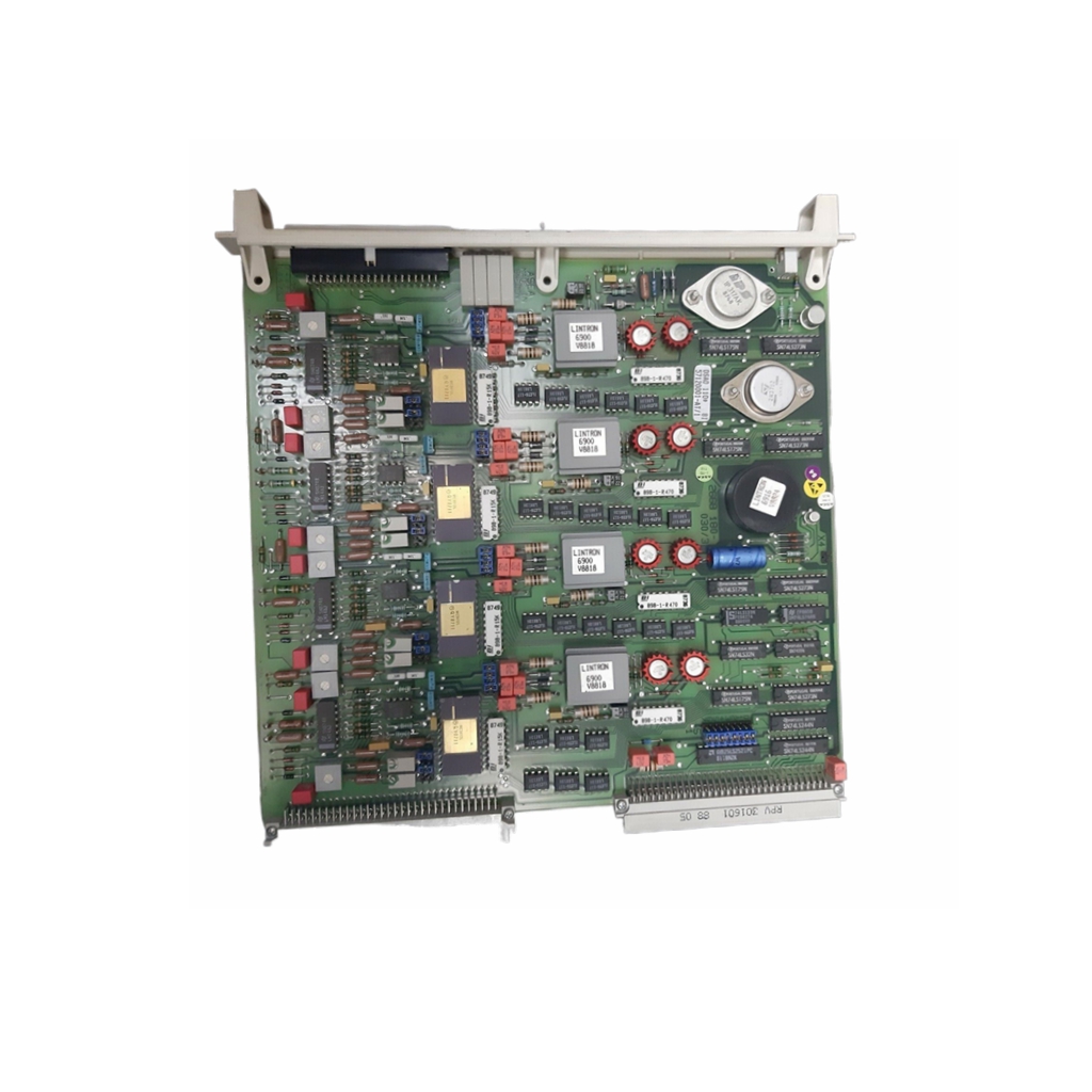
ABB 07KT97H3 Programmable Processor Unit
5 Installation
Pneumatic connections
Air supply
Instrument air*
Purity Maximum particle size: 5 μm
Maximum particle density: 5 mg/m3
Oil content Maximum concentration 1 mg/m3
Pressure dew point 10 K below operating temperature
Supply pressure** Standard design:
1.4 to 6 bar (20 to 90 psi)
Marine version:
1.6 to 5.5 bar (23 to 80 psi)
Air consumption*** < 0.03 kg/h / 0.015 scfm
* Free of oil, water and dust in accordance with DIN / ISO 8573-1. Pollution
and oil content in accordance with Class 3
** Do not exceed the maximum output pressure of the actuator
*** Independent of supply pressure
6 Commissioning
Note
The electrical power supply and supply air pressure data
indicated on the name plate must be complied with during
commissioning.
CAUTION
Risk of injury due to incorrect parameter values!
Incorrect parameter values can cause the valve to move
unexpectedly. This can lead to process failures and result in
injuries.
• Before recommissioning a positioner that was previously
in use at another location, always reset the device to its
factory settings.
• Never start automatic adjustment before restoring the
factory settings!
Note
Please observe the information in Operation on page 32 to
operate the device!
Commissioning the positioner:
1. Open the pneumatic power supply.
2. Power-up the electric power supply and feed in the setpoint
signal 4 to 20 mA.
3. Checking mechanical mounting:
• Press and hold MODE; in addition, press or until
operating mode 1.3 (manual adjustment in the measuring
range) is displayed. Release MODE.
• Press or to move the actuator into the mechanical
end position; check the end positions; rotational angle is
displayed in degrees; for high-speed mode, press or
simultaneously.
Recommended rotational angle range
Linear actuators −28 to 28°
Rotary actuators −57 to 57°
Minimum angle 25°
4. Perform standard automatic adjustment in accordance with
Standard automatic adjustment on page 29.
Commissioning of the positioner is now complete, and the
device is ready for operation.
Operating modes
Selection from the operating level
1. Press and hold down MODE.
2. Also press and release rapidly as often as required. The
selected operating mode is displayed.
3. Release MODE.
The position is displayed in % or as a rotation angle.
Operating mode Mode indicator Position indicator
1.0
Control mode* with
adaptation of the control
parameters M10906a M10906f
1.1
Control mode* without
adaptation of the control
parameters M10906b M10906g
1.2
Manual adjustment** in
the operating range.
Adjust*** using or M10906c M10906g
1.3
Manual adjustment** in
the measuring range.
Adjust*** using or M10906d M10906h
* Since self-optimization in operating mode 1.0 is subject to several factors
during control operation with adaptation, incorrect adjustments could
appear over an extended period.
** Positioning not active.
*** For high-speed mode, press and simultaneously.
Standard automatic adjustment
Note
Standard Auto Adjust does not always result in optimum control
conditions.
Standard automatic adjustment for linear actuators*
1. MODE Press and hold until ADJ_LIN is displayed.
2. MODE Press and hold until the countdown ends.
3. Release MODE; this starts Autoadjust.
Standard automatic adjustment for rotary actuators*
1. ENTER Press and hold until ADJ_ROT is displayed.
2. ENTER Press and hold until the countdown ends.
3. Release ENTER; this starts Autoadjust.
If Autoadjust is successful, the parameters will be stored
automatically and the positioner will revert to operating mode
1.1.
If an error occurs during Autoadjust, the process will be
terminated with an error message.
Perform the following steps if an error occurs:
1. Press and hold down operating button or for
approximately three seconds.
The unit will switch to the operating level, mode 1.3 (manual
adjustment within the measuring range).
2. Check mechanical mounting in accordance with Mechanical
mounting on page 13 and repeat the standard automatic
adjustment.
* The zero position is determined automatically and saved during standard
automatic adjustment, counter-clockwise (CTCLOCKW) for linear actuators
and clockwise (CLOCKW) for rotary actuators
6 Commissioning
Sample parameters
‘Change the zero position of the LCD display from clockwise
(CLOCKW) to counter-clockwise limit stop (CTCLOCKW)’
Initial situation: the positioner is in bus operation on the
operating level.
1. Switching to the configuration level:
• Press and hold down and simultaneously,
• additionally quickly press and release ENTER,
• Wait for the countdown to go from 3 to 0,
• Release and .
The following is now shown in the display:
M10906i
2. Switching to parameter group 3._:
• Press and hold down MODE and ENTER simultaneously,
• additionally quickly press and release 2×,
The following is now shown in the display:
M10906j
• Release MODE and ENTER.
The following is now shown in the display:
M10906k
3. Selecting parameter 3.2:
• Press and hold down MODE,
• additionally quickly press and release 2×,
The following is now shown in the display:
M10906l
— Release MODE.
4. Changing parameter settings:
• Quickly press and release to select CTCLOCKW.
5. Switching to parameter 3.3 (Return to operating level) and
saving the new settings:
• Press and hold down MODE,
• additionally quickly press and release 2×,
The following is now shown in the display:
M10906m
• Release MODE,
• Quickly press and release to select NV_SAVE,
• Press ENTER and hold down until the countdown goes
from 3 to 0.
The new parameter setting is saved and the positioner
automatically returns to the operating level. It continues in the
operating mode that was active prior to the configuration level
being called up.
Setting the option modules
Setting the mechanical position indication
1. Loosen the screws for the housing cover and remove it.
2. Rotate the position indicator on the shaft to the desired
position.
3. Attach the housing cover and screw it onto the housing.
Tighten the screws so that they are hand-tight.
4. Attach the symbol label to mark the minimum and maximum
valve positions on the housing cover.
Note
The labels are located on the inside of the housing cover.
Purchase history
| User name | Member Level | Quantity | Specification | Purchase Date |
|---|
Total 0 Record
Related products

Customer Reviews
Satisfaction :
5 Stars
No evaluation information


- other
- LTI Drives
- ADLINK
- Beckhoff
- Other Brands
- AMAT
- Iba
- PEPPERL+FUCHS
- Aerotech
- WATLOW
- MAN
- ADVANCED
- Abaco
- YOKOGAWA
- KOLLMORGEN
- MEGGITT
- kong-sberg
- METSO
- Motorola
- NI
- OEMAX
- RELIANCE
- scanlab
- schneider
- uniop
- Vibro-Meter
- Honeywell
- Rolls-Royce
- MOOG
- GE
- B&R
- Woodward
- Yaskawa
- xYCOM
- Siemens
- Emerson
- HIMA
- Bently
- ZYGO
- FOXBORO
- OMACO
- PROSOFT
- ENTERASYS
- TRICONEX
- Parker
- Lenze
- KEBA
- Alstom
- CTI
- ABB
- A-B
172

-
 ADLINK AmITX-ALN-N97 Mini ITX Industrial Motherboard
 -
 ADLINK NuPRO-850 Full length ePCI-X Industrial Control Board
 -
 ADLINK MI-965 Mini ITX Industrial Motherboard
 -
 ADLINK M-302 ATX Industrial Motherboard
 -
 ADLINK PXI-3920/PXI-3910 3U PXI System Controller
 -
 ADLINK PCI-8132 Two Axis Servo/Stepper Motion Control Card
 -
 ADLINK cPCI-6760D 6U CompactPCI Single Board Computer
 -
 ADLINK ACL-7122 144 bit digital I/O board
 -
 ADLINK NuPRO-775 Half length Socket370 Industrial Single Board Computer
 -
 ETEL Accuret MODULAR series servo controller
 -
 ADLINK PCI-9112/cPCI-9112 multifunctional acquisition card
 -
 ADLINK PCI-8102 Two Axis Pulse Motion Control Card
 -
 ADLINK PCI-9812/PCI-9810 synchronous 4-channel high-speed acquisition card
 -
 ADLINK PCI-7200/cPCI-7200 high-speed digital I/O board
 -
 ADLINK MXE-1000 series fanless embedded machine
 -
 ADLINK IMB-T10 Mini ITX Industrial Motherboard
 -
 ADLINK HSL Distributed High Speed I/O System
 -
 ADLINK PXI/DAQ/DAQe-2500 series multifunctional analog output DAQ card
 -
 ADLINK PXI/DAQ/DAQe-2200 series multifunctional data acquisition card
 -
 ADLINK ETX-AT ETX Core Computer Module
 -
 ADLINK ACL-7225 ISA 16 channel relay output+16 channel isolated digital input card
 -
 ADLINK DAQ-2000 series synchronous acquisition card
 -
 ADLINK NuPRO-E330 PICMG 1.3 full-length industrial motherboard (SHB)
 -
 ADLINK ACL-8112 series multifunctional ISA acquisition card
 -
 ADLINK USB-2405 24 bit dynamic signal acquisition module
 -
 ADLINK PXIS-3320 15 slot 6U PXI chassis
 -
 ADLINK PCIe GIE7x series acquisition card
 -
 ADLINK PCIe-7856/PCIe-7853 Distributed Motion and IO Main Controller PCIe Acquisition Card
 -
 ADLINK PCI-6308 series isolated analog output board
 -
 ADLINK PCI-7432 Isolated Digital I/O Acquisition Card
 -
 ADLINK NuPRO-E72 PICMG 1.3 Full length Industrial SHB Single Board Computer
 -
 ADLINK MXE-5400 series fanless embedded industrial computer
 -
 ADLINK M-322 Industrial ATX Motherboard
 -
 ADLINK IMB-M43H Industrial ATX Motherboard
 -
 ADLINK IMB-M42H Industrial ATX Motherboard
 -
 ADLINK i915GV-INA ATX motherboard
 -
 ADLINK ETX-NR667 Embedded ETX Standard Computer Module
 -
 ADLINK ETX-BT (PATA to SATA version) User Manual
 -
 ADLINK CM1-BT1 PC/104 Single Board Computer
 -
![ADLINK cPCI-8217 [R] 3U CompactPCI VGA/LCD Display Module](https://aosspic10001.websiteonline.cn/hkw632bc8/image/image_aJXQRn.png) ADLINK cPCI-8217 [R] 3U CompactPCI VGA/LCD Display Module
ADLINK cPCI-8217 [R] 3U CompactPCI VGA/LCD Display Module -
 ADLINK AmITX-SL-G Mini ITX Embedded Motherboard
 -
 ADLINK AmITX-AL-I ultra-thin Mini ITX industrial motherboard
 -
 ADLINK NuPRO-E315 Full length PICMG 1.3 Industrial SHB Single Board Computer
 -
 ADLINK NuPRO-842 Full length PICMG 1.0 PCI/ISA Industrial Single Board Computer
 -
 ADLINK NuPRO-900A PICMG 1.2 ePCI-X Dual Xeon Industrial System Motherboard (SHB)
 -
 ADLINK cPCI-6910 series 6U CompactPCI single board computer
 -
 ADLINK cPCI-6860A 6U CompactPCI dual core single board computer with cPCI-R6860A rear adapter board
 -
 ADLINK cPCI-8168 6U CompactPCI Eight Axis Motion Control Card
 -
 ADLINK NuPRO-E340 PICMG 1.3 Industrial SHB motherboard
 -
 ADLINK NuPRO-A40H Full length PICMG1.0 Industrial Single Board Computer (SBC)
 -
 ADLINK NuPRO-852 Full length PICMG1.0 Industrial Single Board Computer
 -
 ADLINK NuPRO-841 Full length Industrial SBC
 -
 ADLINK NuPRO-590/591/592 series Socket7 full-length industrial SBC
 -
 ADLINK MXE-5500 series fanless embedded industrial computer
 -
 ADLINK MXE-200/200i Fanless Embedded Machine
 -
 ADLINK cPCI-6770 series CompactPCI CPU board
 -
 ADLINK NuPRO-A301 standard PICMG 1.0 full-length industrial SBC single board computer
 -
 ADLINK NuPRO-965 PICMG 1.3 SHB Express Full length Industrial Motherboard
 -
 ADLINK NuPRO-935A Full length PICMG1.0 Industrial Single Board Computer
 -
 ADLINK NuPRO-865 Full length Single Board Computer
 -
 ADLINK NuPRO-840 DV/LV Full Length PICMG Industrial Single Board Computer
 -
 ADLINK NuPRO-770 series full-length industrial single board computer
 -
 ADLINK NuPRO-595 series half length Socket 7 industrial motherboard
 -
 ADLINK cPCI-6840 series 6U CompactPCI single board computer
 -
 Foxboro 43AP series pneumatic indicator controller (PSS 3-1B3 A)
 -
 ADLINK cPCI-3720 Series 3U Low Power CompactPCI Single Board Computer
 -
 ADLINK NuPRO-E47, PICMG 1.3 full-length industrial SHB system motherboard
 -
 ADLINK NuPRO-E43 PICMG 1.3 full-length system motherboard
 -
 ADLINK NuPRO-780 series full-length industrial CPU board
 -
 ADLINK cPCI-6965 series 6U CPCI single board computer
 -
 ADLINK USB/LPCI/LPCIe-3488A GPIB interface card
 -
 Rittal SK 3241.700 Blue e+Fan Filter Unit
 -
 ADLINK cPCI-8168 6U CompactPCI 8-Axis Motion Control Card
 -
 ADLINK PCIe PXIe-8638 PCIe to PXIe Bus Expansion Kit
 -
 ADLINK PCIe GIE7x series acquisition card
 -
 ADLINK PCIe-7396 96 96 channel TTL digital IO card
 -
 ADLINK PCI/MPC/PXI-8164 Three in One Motion Control Card
 -
 ADLINK PCI-8154 Four Axis Pulse Motion Control Card
 -
 ADLINK PCI-8134 Four Axis Servo/Stepper Motion Control Card
 -
 ADLINK NuPRO-E42 PICMG1.3 full-length SHB motherboard
 -
 ADLINK MXC-6600 series high-performance fanless extended industrial computer
 -
 ADLINK MXC-6000 series embedded industrial control computer
 -
 ADLINK MXC-2300 series fanless expandable embedded industrial computer
 -
 ADLINK MCM-204 Independent Ethernet DAQ User Manual
 -
 ADLINK MCM-100/102 Edge IoT Platform for Machine Condition Monitoring User’s Manual
 -
 ADLINK MXC-6400 series sixth generation Core Fanless Scalable Industrial Control Computer
 -
 ADLINK Matrix Full Series Fanless Embedded Industrial Control Computers
 -
 ADLINK GIE64+4-channel PoE Gigabit Vision Capture Card
 -
 Honeywell UMS Security System Troubleshooting Guide
 -
 Honeywell Expert Series-C I/O Module
 -
 ADLINK EOS-1200 Embedded Vision Host
 -
 ADLINK DLAP-5200 series high-performance fanless AI industrial computer
 -
 ADLINK DLAP-4000 series embedded industrial control computer
 -
 ADLINK Matrix MXC-2000 Series Fanless Industrial Control Computer Specification
 -
 ADLINK DAQ -/DAQE -/PXI-2000 Series Multi functional Synchronous Acquisition Card
 -
 ADLINK cPCI-6520 6U CompactPCI Single Board Computer
 -
 ADLINK CM1-86DX3 PC/104 Single Board Computer
 -
 Honeywell DC1000 series PID temperature controller
 -
 ALSTOM MiCOM C264 Modular Substation Controller
 -
 EMERSON AMS 2140 Mechanical Health Analyzer
 -
 ADLINK NuPRO-E320 PICMG1.3 Full length Industrial Motherboard
 -
 ADLINK NuPRO-800 Series Full length Industrial SBC User Manual
 -
 ADLINK NuPRO-598 Industrial Single Board Computer
 -
 ADLINK MXC-6300 Fanless Embedded Industrial Control Computer
 -
 ADLINK Express-BASE7 User Manual
 -
 ADLINK DLAP-211 Series Fanless Edge AI Platform Specification Manual
 -
 ADLINK PCI/LPCI/LPCIe/cPCI-723X series 32 channel isolated digital I/O card
 -
 ADLINK cPCI-6965 series 6U CompactPCI single board computer
 -
 ADLINK NuDAQ 7200 series high-speed digital I/O board
 -
 Linghua ADLINK DLAP Deep Learning Acceleration Platform Product Manual
 -
 DEIF TCM-2 thyristor control module
 -
 Installation Manual for DEIF MVR-200 Series Medium Voltage Protection Device
 -
 DEIF MDR-2 multifunctional differential relay
 -
 DEIF AOM-1 Analog Output Module
 -
 DEIF AGI 400 series industrial/marine touch screen
 -
 Installation Manual for DEIF BRW-1 Marine Wing Bridge Instrument
 -
 DEIF AGC200 Quick Start Guide
 -
 DEIF AGC Multi line 2 Generator Set ControllerProduct basic information
 -
 ABB SPA-ZC 400 Ethernet Gateway Installation and Debugging Manual
 -
 ABB REM 543/545 motor generator protection device
 -
 DEIF PPU 300 controller
 -
 DEIF Delomatic 4 Offshore/Ocean Platform Dedicated Generator Power Management System DM-4
 -
 DEIF Delomatic Modular Generator Set Integrated System
 -
 DEIF AGC-4 Mk II Generator Set Controller
 -
 DEIF AGC-4 diesel generator set integrated controller
 -
 DEIF Multi line 2 Series PPU Unit Power Management (PPM) Operation Manual
 -
 DEIF Multi line 2 V2.4X Installation Manual
 -
 Beckwith M-6280 Digital Capacitor Bank Controller

K-JIANG

Add: Jimei North Road, Jimei District, Xiamen, Fujian, China
Tell:+86-15305925923