
K-WANG
+086-15305925923
Service expert in industrial control field!


Product
Article
NameDescriptionContent
Adequate Inventory, Timely Service
pursuit of excellence


Ship control system
Equipment control system
Power monitoring system
Brand
Product parameters
- Telephone:+86-15305925923
- contacts:Mr.Wang
- Email:wang@kongjiangauto.com
Description
The Analog Output module provides eight 0 to 21.0 mA
outputs that may be scaled by the user to any span within
this range on a per output basis. Outputs are isolated in
groups of 4 with no isolation between outputs in a group.
All points are isolated from controller logic
Honeywell Analog Input (8 channel)900A01-0202
Analog Output Module (900B08-xxxx)The Analog Output module provides eight 0 to 21.0 mA
outputs that may be scaled by the user to any span within
this range on a per output basis. Outputs are isolated in
groups of 4 with no isolation between outputs in a group.
All points are isolated from controller logic.
A green blinking status LED on the module indicates when
the module is being scanned. A red status LED when
module or channel diagnostics exist. A user specified
failsafe value is supported to allow predictable operation in
the event communication between the module and the
controller is interrupted.
Outputs are updated synchronous with control execution. A
user-specified rate of change limit may be applied to each
output when needed. Requires Euro style 36-terminal
terminal block.
A DIP switch on the module selects the use of 24V from
Rack PS (internal) power or external loop power via a
separate 24V DC power source. The as-shipped (default)
switch setting is external power.
External Power Source requirements:
Voltage Vin: 18 to 36 Vdc
Current 350 mA per module
Outputs per module 8, isolated in 2 groups of 4 outputs (1-4, 5-8)
Current 0 to 21.0 mA, range selectable
Load resistance 750 ohms max
Galvanic Isolation 500VDC group to group. Groups 1-4, 5-8
Galvanic Isolation from logic
500 VDC
Accuracy 0.1% full scale at reference conditions
Modules per rack 4 max when powered from internal 24V
backplane power
Minimum current sensing >0.5mA per output
Calibration Data Data is stored in non-volatile memory.
Redundant Factory Calibration, with
automatic rejection of Bad version. Individual
Channel Field Calibration
Diagnostics Monitoring of Factory Calibration, Field
Calibration, Configuration
Output Verification Feedback to controller to indicate output
current is flowing.
D/A Resolution 13+ bits (1 part in 13332)
Power Supply Loading 5V ; 225 mA max
24V ; 350 mA max
Terminal Block 36 Position – Euro style, (Model 900TCK-0001)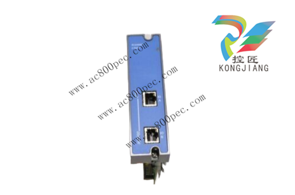
Analog Output Module (900B16-xxxx)
The Analog Output module provides 16, 0 to 21.0 mA
outputs that may be scaled by the user to any span within
this range on a per output basis. Outputs are isolated in
groups of 4 with no isolation between outputs in a group.
All points are isolated from controller logic.
A green blinking status LED on the module indicates
when the module is being scanned. A red status LED
when module or channel diagnostic exist. A user
specified failsafe value is supported to allow predictable
operation in the event communication between the
module and the controller is interrupted.
Outputs are updated synchronous with control execution.
A user-specified rate of change limit may be applied to
each output when needed. Requires Euro style 36-
terminal terminal block.
A DIP switch on the module selects the use of 24V from rack PS (internal) power or external loop power via a separate 24V
DC power source. The as-shipped (default) switch setting is external power.
External Power Source requirements:
Voltage 18 to 36 Vdc
Current 700 mA per module
Outputs per module 16, isolated in 4 groups of 4 outputs (1-4, 5-8, 9-12, 13-16)
Current 0 to 21.0 mA, range selectable
Load resistance 750 ohms max
Galvanic Isolation 500VDC group to group. Groups 1-4, 5-8, 9-12, 13-16.
Galvanic Isolation
from logic
500 VDC
Accuracy 0.1% full scale at reference conditions
Modules per rack 2 max when powered from internal 24V backplane power.
Minimum current
sensing
> 0.5mA per output
Calibration Data Data is stored in non-volatile memory. Redundant Factory
Calibration, with automatic rejection of Bad version.
Individual Channel Field Calibration
Diagnostics Monitoring of Factory Calibration, Field Calibration, and
Configuration.
Output Verification Feedback to controller to indicate output current is flowing.
D/A Resolution 13+ bits (1 part in 13332)
Power Supply
Loading
5V ; 350 mA max
24V ; 700 mA max
Terminal Block 36 Position – Euro style, (Model 900TCK-0001)
Purchase history
| User name | Member Level | Quantity | Specification | Purchase Date |
|---|
Total 0 Record
Related products
Customer Reviews
Satisfaction :
5 Stars
No evaluation information


- other
- ADLINK
- LTI Drives
- Other Brands
- AMAT
- Iba
- PEPPERL+FUCHS
- Aerotech
- WATLOW
- MAN
- ADVANCED
- Abaco
- YOKOGAWA
- KOLLMORGEN
- MEGGITT
- kong-sberg
- METSO
- Motorola
- NI
- OEMAX
- RELIANCE
- scanlab
- schneider
- uniop
- Vibro-Meter
- Honeywell
- Rolls-Royce
- MOOG
- GE
- B&R
- Woodward
- Yaskawa
- xYCOM
- Siemens
- Emerson
- HIMA
- Bently
- ZYGO
- FOXBORO
- OMACO
- PROSOFT
- ENTERASYS
- TRICONEX
- Parker
- Lenze
- KEBA
- Alstom
- CTI
- ABB
- A-B
142

-
 DEIF TCM-2 thyristor control module
 -
 Installation Manual for DEIF MVR-200 Series Medium Voltage Protection Device
 -
 DEIF MDR-2 multifunctional differential relay
 -
 DEIF AOM-1 Analog Output Module
 -
 DEIF AGI 400 series industrial/marine touch screen
 -
 Installation Manual for DEIF BRW-1 Marine Wing Bridge Instrument
 -
 DEIF AGC200 Quick Start Guide
 -
 DEIF AGC Multi line 2 Generator Set ControllerProduct basic information
 -
 ABB SPA-ZC 400 Ethernet Gateway Installation and Debugging Manual
 -
 ABB REM 543/545 motor generator protection device
 -
 DEIF PPU 300 controller
 -
 DEIF Delomatic 4 Offshore/Ocean Platform Dedicated Generator Power Management System DM-4
 -
 DEIF Delomatic Modular Generator Set Integrated System
 -
 DEIF AGC-4 Mk II Generator Set Controller
 -
 DEIF AGC-4 diesel generator set integrated controller
 -
 DEIF Multi line 2 Series PPU Unit Power Management (PPM) Operation Manual
 -
 DEIF Multi line 2 V2.4X Installation Manual
 -
 Beckwith M-6280 Digital Capacitor Bank Controller
 -
 Beckwith M-3311 Transformer Protection Relay
 -
 Beckwith M-3311A Transformer Integrated Protection Device
 -
 Beckwith M-3310 Transformer Integrated Protection Device Specification
 -
 Beckwith M-0359 Syncrocloser Check Plus Application Guide for Synchronous Calibration Relay
 -
 Beckwith M-0293A On Load Tap changer Controller Application Guide
 -
 DEIF GPU-3 Synchronous/Asynchronous Generator Integrated Microcomputer Protection Controller
 -
 Installation Instructions for DEIF PPM-3
 -
 Beckwith M-3520 distributed power grid connected comprehensive protection device
 -
 Beckwith M-3430 generator comprehensive protection device
 -
 Beckwith M-2293B adapter panel
 -
 Beckwith M-2001C digital on load voltage regulator controller
 -
 Beckwith M-2001B Digital On Load Voltage Regulating Controller
 -
 Beckwith M-0388/M-0389 synchronous verification relay
 -
 Beckwith M-0193B synchronous closing device
 -
 Beckwith M-0115A Transformer Parallel Balancing Module
 -
 Beckwith M-0067E on load tap changer controller
 -
 Beckwith M-4272 Digital Motor Bus Switching System
 -
 Beckwith M-3311A Transformer Integrated Protection Device
 -
 Beckwith M-3425A Generator Integrated Protection Device Manual
 -
 Basler BE1-27/BE1-59/BE1-27/59 undervoltage/overvoltage relay
 -
 Basler AVC63-12/AVC125-10 excitation voltage regulator
 -
 Basler L301kc Color Three Line Array Camera Operation Manual
 -
 Basler CBS 212A Current Enhanced Excitation System
 -
 Basler BE3-25 synchronous check relay
 -
 Operation Manual for Basler BE1-32R/BE1-32O/U Direction Power Relay
 -
 Basler Electric PRS-250 Veri Sync Synchronous Relay
 -
 Basler Pilot Series Area Array Industrial Camera piA2400-17gc
 -
 Basler BE1-11g comprehensive protection device for generator
 -
 Basler VR63-4C/UL Analog Excitation Voltage Regulator
 -
 Basler BE1-DFPR distribution feeder protection relay
 -
 Basler CBS310/CBS320 current strong excitation system
 -
 Basler UFOV250A/UFOV260A Low Frequency Overvoltage Module
 -
 Basler MVC104/MVC108/MVC232 manual voltage control device
 -
 Basler XR2002/XR2002F PMG excitation regulator
 -
 Basler DECS-400 Digital Excitation Control System
 -
 Basler DGC-2020 Digital Generator Set Controller
 -
 Basler MVC-300 Electronic Manual Excitation Controller
 -
 Basler MVC-104/MVC-108/MVC-232 manual excitation controller
 -
 Basler SSR32-12/SSR63-12/SSR125-12 Static Excitation Voltage Regulator
 -
 Basler SR4A/SR8A Analog Excitation Voltage Regulator
 -
 Basler BE2000E Digital Excitation Voltage Regulator
 -
 Basler DECS-2100 Digital Excitation System
 -
 Basler BE1-851 Overcurrent Protection Device Manual
 -
 Basler APR 63-5 Voltage Regulator
 -
 Basler BE1-FLEX Integrated Protection Control System
 -
 Basler BE1-700V digital voltage protection relay
 -
 Basler BE1-87B high impedance bus differential relay
 -
 Basler BE1-40Q demagnetization relay
 -
 Basler BE1-60 Voltage Balance Relay
 -
 Basler BE1-47N negative sequence voltage phase sequence relay
 -
 Basler BE1-81O/U digital frequency relay
 -
 Basler BE1-11f Feedline Integrated Protection Device Manual
 -
 Basler DECS-250 Digital Excitation Control System
 -
 Basler DECS-100 Digital Excitation Control System
 -
 Basler BE1-BPR Circuit Breaker Protection Relay
 -
 Basler BE1-50/51B-255 overcurrent relay
 -
 Basler BE1-25 synchronous check relay
 -
 Basler BE1-51 microcomputer time limited overcurrent relay
 -
 Basler DECS-300 Digital Excitation Control System
 -
 Mitsubishi MELSEC-F FX series programmable controllers
 -
 Hirschmann cSCALE Mobile Machinery Modular Controller
 -
 Hirschmann OZD Profi G12DU/G12DK/G12DE ATEX1 PROFIBUS Fiber Optic Repeater Manual
 -
 Hirschmann OCTOPUS OS20/OS24 Network Managed IP65/IP67 Industrial Switch Installation Manual
 -
 Hirschmann RS20/RS22/RS30/RS32/RS40 Series Industrial Rail Switch Installation Manual
 -
 Hirschmann EAGLE One Industrial Ethernet Firewall Installation Manual
 -
 Hirschmann MACH102 Series Industrial Switch Installation Manual
 -
 Hirschmann MS20/MS30 Modular Industrial Switch Installation Manual
 -
 Hirschmann BRS20/22/30/32/40/42/50/52 Series BOBCAT Industrial Rail Switch Installation Manual
 -
 Hirschmann RSB20 Basic Series Industrial Rail Switch Installation Manual
 -
 Hirschmann RS20 Basic Series Industrial Ethernet DIN-Rail Switches
 -
 BECKHOFF EP20xx/EP28xx IP67 EtherCAT Box Digital Output Module
 -
 BECKHOFF EL5102 Incremental Encoder Terminal Manual
 -
 BECKHOFF CU8803-000x CP Link4 Launch Box Operation Manual
 -
 Beckhoff CU20xx/CU22xx Industrial Unmanned Switch Manual
 -
 BECKHOFF AMP8000 Distributed Servo System Operation Manual
 -
 BECKHOFF EL2911/EL2911-2200 TwinSAFE Safety Potential Supply Terminal Manual
 -
 BECKHOFF EL600x/EL602x series EtherCAT serial port terminal module
 -
 BECKHOFF CP6700-0001-0050/0060 Integrated Machine Manual
 -
 BECKHOFF CP70xx Series Control Panel Installation and Operation Manual
 -
 BECKHOFF CP29xx Cabinet Mounted Industrial Touch Panel Official Operation Manual
 -
 Beckhoff C6650-0060 Control Cabinet Industrial PC
 -
 Beckhoff BK series K-bus to EtherCAT coupler
 -
 Beckhoff CX20x0 Series Embedded Industrial Control Computer Manual
 -
 Beckhoff CP77xx Series Industrial Panel PC Installation and Operation Manual
 -
 Beckhoff EL41xx Series 16 Bit Analog Output Terminal Manual
 -
 Beckhoff C63xx-0020 series control cabinet industrial PC
 -
 Beckhoff C6920-0060 Control Cabinet Industrial PC
 -
 Beckhoff CU8800-0010 USB transmitter extender (TX)
 -
 Beckhoff AX2000 series digital servo amplifier
 -
 Beckhoff AX8000 Modular Multi Axis Servo System
 -
 Beckhoff CP27xx Embedded Panel PC User Manual
 -
 Beckhoff CP69xx Industrial Embedded Control Panel
 -
 Beckhoff CP60xx Embedded Industrial Control Panel
 -
 Beckhoff CP72xx series panel PC official installation, operation, configuration, maintenance, and troubleshooting
 -
 Installation and Operation of Beckhoff CP78xx Series Control Panel
 -
 Beckhoff CP39xx series industrial touch control panel
 -
 Beckhoff CX8110 Embedded Industrial PC
 -
 Beckhoff CX50x0 series DIN rail embedded industrial PC
 -
 Beckhoff CP62xx series embedded panel PC
 -
 BECKHOFF C6030 Compact Industrial PC
 -
 UniOP ePAD32B/ePAD33B/ePAD33BT Industrial HMI
 -
 UniOP ePAD05&ePAD06 Industrial HMI
 -
 UniOP ePAD03/ePAD04 entry-level HMI
 -
 UniOP CP01R-04 Compact Industrial HMI
 -
UniOP BKDR-16 Industrial Human Machine Interface
-
 Beckwith M-3425A Generator Integrated Protection Relay
 -
 Basler DECS-200 Digital Excitation Control System
 -
 Basler DECS-250 Digital Excitation Control System Manual
 -
 HA-800 series AC servo drive
 -
 JUMO dTRANS p35 Pressure Sensor Operation Manual with IO Link Interface

K-JIANG

Add: Jimei North Road, Jimei District, Xiamen, Fujian, China
Tell:+86-15305925923