
K-WANG
+086-15305925923
Service expert in industrial control field!
Product
Article
NameDescriptionContent
Adequate Inventory, Timely Service
pursuit of excellence


Ship control system
Equipment control system
Power monitoring system
Current position:
Brand
Product parameters
- Telephone:+86-15305925923
- contacts:Mr.Wang
- Email:wang@kongjiangauto.com
Description
Overview
This section contains descriptions of and procedures for installing I/O Modules in controller racks
(C30/C30S, C50/C50S, C70/C70S, models) and in I/O expansion racks (S50/S50S, S75/S75S only).
Honeywell 8 ch A/O RTP Cable (1.0M, 3.3ft) Note 6 (NOT FOR SIL2 SYSTEMS) 900RTC-B910
I/O Module Installation and Wiring
Overview
This section contains descriptions of and procedures for installing I/O Modules in controller racks
(C30/C30S, C50/C50S, C70/C70S, models) and in I/O expansion racks (S50/S50S, S75/S75S only).
Module Placement in Racks
Each input or output module is placed in an I/O slot in a rack as shown in Figure 37.
Each “slot” in a rack includes a set of guides that locate the circuit board in the rack and a 20-pin (4 x 5)
socket in the backplane that receives the associated 4 x 5-pin plug at the back of the I/O module.
At the front of each I/O module, a 20 or 36 pin plug receives the associated socket on the back of a terminal
block. When the I/O module is inserted into the rack and the terminal block is placed on the circuit board,
two captured screws in the terminal block are fastened to metal tabs on the rack.
Figure 37 – I/O Module Installation
Do not use an input/output terminal block if the terminal block is damaged, if the door is
missing, or if one or both mounting screws are missing.
Always tighten both terminal block screws to proper torque settings before applying field
power to the module. Torque to 0,4 - 0,5 Nm (3.5 – 4.4 Lb-In.)
Do not apply energized (“live”) field wiring to an input/output module that is not installed in
one of the racks in the HC900 Controller.
Do not operate the controller without a Protective Earth connection.
Failure to comply with these instructions could result in death or serious injury.Terminal Block Styles
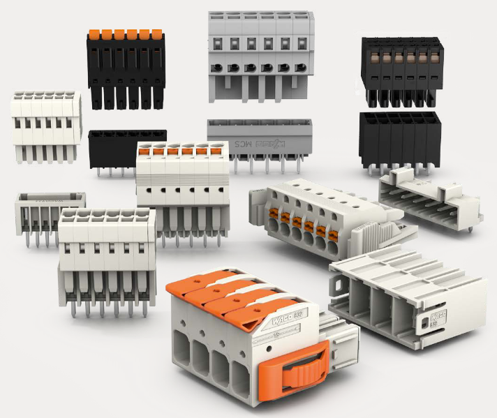
The terminal block is available in the barrier style, shown at
left in Figure 38, and the Euro style, shown at right. Not
shown: a Euro style with 36 connections is also available
for certain high capacity modules.
Terminal blocks have an embossed numbering “key” that
shows the numbering pattern of the 20/36 connections.
The frame associated with the terminal block has a
transparent hinged door. The hinged door is a tool secured
cover. To open the door, insert a flat screwdriver into the
slot at the top and bottom of the door while pulling out. The
door has molded-in tabs that hold labels, which are uniquely
color-coded to identify each module type.
Each label is printed on both sides. On the front (visible
when the door is closed) are I/O channel numbers, with
spaces in which tag names can be written. On the back
(visible when the door is open) are wiring patterns for the
type of module located in the slot.
Figure 38 – Terminal Block Styles
The 20-pin, inline connectors at the back of the terminal blocks are universal; that is, any type of I/O
module can be used with either the Barrier style or the Euro style terminal block. The 36-pin Euro terminal
blocks must be used with High Level AI, High Level AO, 32 DI, and 32 DO modules.
ATTENTION
Before mounting terminal blocks in the rack, be sure they are properly keyed to the
module type they will be used with. See I/O Module Installation Procedures, page 84.
Terminal Block Colors and Keying
Both the barrier style and the Euro style are available in two colors (red and black). Black terminal blocks,
which have gold contacts, are used for low-voltage, low-energy signals such as analog inputs, contact
inputs and low DC voltages. Red terminal blocks, which have tin contacts, are used for higher voltages
such as 120/240 Vac.
Colors of each Terminal Blocks must correlate to that of the mating header on I/O modules with which they
are used; that is:
Black terminal blocks, which have gold contacts, are for use with I/O modules that have black headers
and gold pins in the 20-pin connector; these include: Analog Input, 4-channel Analog Output, DC Input,
DC Output, Contact Input, Pulse Input, Pulse Output, Frequency Input, Quadrature Input.
Red terminal blocks, which have white (tin) contacts, are for use with I/O modules that have red headers
and white- (tin-) contacts in the 20-pin connector; these include: AC Input, AC Output, and Relay
Output.
36-pin black Euro terminal blocks, which have gold contacts, are for use with 8-point AO, 16-point AO,
16-point AI, 32-point DI, and 32-point DO modules.
Terminal blocks must be keyed by the installer to prevent high voltage terminal blocks from being
installed on low voltage modules. See Table 14.
Any of the color-coded labels will fit into the door of any terminal block. Use care to ensure that all
hardware components match each other, and also match the control strategy in the configuration file.
Remote Termination Panel (RTP)
The optional Remote Termination Panel (RTP) provides an easy way to connect the HC900 controller to
the field wiring. The RTP integrates some of the typical externally connected components, reducing wiring
and setup time. It also minimizes the need for multiple wires under a single screw connection by
expanding the connectivity of the shared terminals of the I/O modules.
See Appendix - Installation of Remote Termination Panels (RTPs) page 217 for details.
Terminal Block-to-Field (Signal) Wiring
Although both of the two available terminal block styles can be used on all I/O module types, wiring
methods vary with the module type and with the type of field devices connected to the terminal block. The
descriptions that follow provide details.
Wiring can be routed through the terminal block at the top, at the bottom, or both. Wiring should be fixed
in place using wire ties at the slotted tabs that are molded in at top and bottom of each terminal block.
Wiring Rules and Recommendations
In general, stranded copper wire should be used for non-thermocouple electrical connections. Twisted-pair
wiring with shielded cable is recommended and will improve noise immunity if wire routing is suspect.
Wire Gage
Observe all local codes when making power connections. Unless local electrical codes dictate otherwise,
the recommended minimum wire size for connections is given in Table 12.
Table 12 – Minimum Recommended Wire Sizes
Wire
Gauge
Wire Application
14 Earth ground to common power supply.
14 to 16 AC to power supply
10 to 14 Earth ground wire
20 DC current and voltage field wiring
22 DC current and voltage wiring in control room
Routing and Securing Wires
Typically, field wiring is routed to connections at a terminal panel near the controller and then from the
terminal panel to the terminal blocks on the I/O modules.
Whatever method of routing is used, wiring must be mechanically supported along its length, and must be
protected from physical damage and electromagnetic (noise) interference. (See Electrical Considerations
page 56.)
Also, all wires must be securely terminated, using appropriate wiring practices.
Signal Grounding (
Figure 39)
The shield for each input should be grounded
at the grounding bar (optional) at the top or
bottom of each rack as indicated in Figure 40.
For low-frequency noise rejection, I/O wiring
shields should be grounded only at the
controller end.
For high-frequency noise rejection, shields
should be grounded at the controller and at
the field device. If the ground voltage
potential at the field device is different from
that at the controller, a DC isolation capacitor
should be used between the shield and the
grounding bar on the rack.
Figure 39 – Signal-Wire Grounding
Aluminum grounding bars for I/O wiring are available as options. When selected for use, they are fastened
to the top and/or bottom of each rack, as indicated in Figure 40. To enable connection of multiple ground
wires with a single screw, the wires can be twisted together and secured with a wire lug.
To facilitate module replacement, it is advisable in most cases to route all wiring through either the top or
the bottom of the terminal block. This
allows the terminal block to pivot up or
down, allowing ready access to the
module, and is the preferred method
for a limited number of wires.
For a larger number of wires, or for
wires of a heavier gauge, it is advisable
to route some wires through the top of
the terminal block, and some through
the bottom, as indicated in Figure 40.
In this case, it is necessary to adjust
wire length so as to ensure adequate
flexibility of the twisted wires and to
provide clearance sufficient to remove
the I/O module.
Purchase history
| User name | Member Level | Quantity | Specification | Purchase Date |
|---|
Total 0 Record
Related products
Customer Reviews
Satisfaction :
5 Stars
No evaluation information


KONG JIANG


Add: Jimei North Road, Jimei District, Xiamen, Fujian, China
Tell:+86-15305925923


