
K-WANG
+086-15305925923
Service expert in industrial control field!


Product
Article
NameDescriptionContent
Adequate Inventory, Timely Service
pursuit of excellence


Ship control system
Equipment control system
Power monitoring system
Brand
Product parameters
- Telephone:+86-15305925923
- contacts:Mr.Wang
- Email:wang@kongjiangauto.com
Description
Carefully place the Power
Supplies in the slots in the
Rack, ensuring that the
connector at the back seats
properly. See Table 9 steps 1
and 2 for power supply wiring
details.
Honeywell LV RTP Cable (32/16 channel) (5.0M, 16.4ft) Note 6 (NOT FOR SIL2 SYSTEMS) 900RTC-3350
Step Procedure Comments/References
1 Carefully place the Power
Supplies in the slots in the
Rack, ensuring that the
connector at the back seats
properly. See Table 9 steps 1
and 2 for power supply wiring details.
Note: It is recommended each
power supply should be
powered from a separate
power source and a power
switch should be installed to
allow for servicing of each
Processor/Supply separately.
2 Set controller communication ports.
See page 42.
3.Ensure that AC power to the
rack is disconnected.
Carefully place the Controller
Modules in the rack, adjacent
to the Power Supplies.
Fasten them in place with
captured screws at top and bottom.
Torque to 0,4 -0,5 N.m
(3.5 – 4.4 Lb-In).
ATTENTION:
The CPU battery comes
installed with a plastic tab
protruding from the battery
cover. This tab breaks the
battery circuit. Do not
remove this tab at this time.
Removing the tab before
the controller is configured
can substantially shorten
battery life. Remove the tab
under power after the
controller configuration is complete.
(For more information, refer to Battery
Installation/Replacement, page 203.)
See figure in step 1.
4 Insert the RSM in the middle
slot and attach with screws at
top and bottom.
See figure in step 1.
Assemble I/O Expansion Racks
I/O Expansion Rack assembly information is given in Table 11.
Table 11 – Assemble I/O Expansion Racks
Step Procedure Comments/References
1 Insert power supply into left-most slot
in the I/O rack. See Table 9 steps 1
and 2 for wiring details.
If using redundant power, your I/O rack will contain a second
smaller compartment, see 1 in the following figure. Insert first
power supply in the larger compartment as shown, to the
immediate right of the plate dividing the two compartments.
2 Redundant Power (optional):
Insert the second power supply in the
left side of the smaller compartment,
see 1 in figure above. See Table 9
steps 1 and 2 for details.
Insert the PSM between the 2 power
supplies. Fasten it in place with
screws at top and bottom.
See 1 in figure above. See Table 9 steps 1 and 2 for wiring
details.
Step Procedure Comments/References
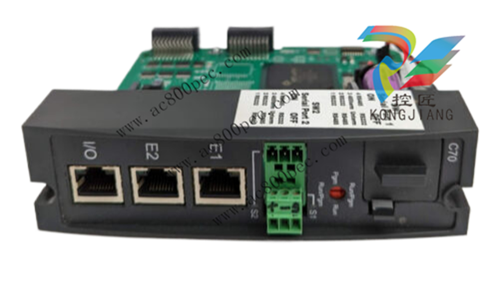
3 Set scanner address for the I/O rack
using the Scanner Module DIP
switches on SW3 (shown at right). For
C50/C70, use addresses 1-11. For
C75, use addresses 1-12.
Scheme 1 (upto 5 racks):
DIP switches 6-8 must be OFF. Only
one DIP switch may be ON:
DIP switch 1 ON = Scanner 1
DIP switch 2 ON = Scanner 2
DIP switch 3 ON = Scanner 3
DIP switch 4 ON = Scanner 4
DIP switch 5 ON = Scanner 5
Scheme 2 (upto 12 racks):
DIP switch 6 NO Always and
1 ON = Scanner 1
2 ON = Scanner 2
2 & 1 ON = Scanner 3
3 ON = Scanner 4
3 & 1 ON = Scanner 5
3 & 2 ON = Scanner 6
3 & 2 & 1 ON = Scanner 7
4 ON = Scanner 8
4 & 1 ON = Scanner 9
4 & 2 ON = Scanner 10
4 & 2 & 1 ON = Scanner 11
4 & 3 ON = Scanner 12
A small slotted screwdriver or
paperclip works well; avoid pencils.
4 Repeat steps 1 through 3 for each I/O
expansion rack.
Then, for each I/O expansion rack,
insert the Scanner Module
immediately to the right of the Power
Supply, and secure it in place with the
two captured screws in the faceplate.
Purchase history
| User name | Member Level | Quantity | Specification | Purchase Date |
|---|
Total 0 Record
Related products
Customer Reviews
Satisfaction :
5 Stars
No evaluation information


- other
- ADLINK
- LTI Drives
- Other Brands
- AMAT
- Iba
- PEPPERL+FUCHS
- Aerotech
- WATLOW
- MAN
- ADVANCED
- Abaco
- YOKOGAWA
- KOLLMORGEN
- MEGGITT
- kong-sberg
- METSO
- Motorola
- NI
- OEMAX
- RELIANCE
- scanlab
- schneider
- uniop
- Vibro-Meter
- Honeywell
- Rolls-Royce
- MOOG
- GE
- B&R
- Woodward
- Yaskawa
- xYCOM
- Siemens
- Emerson
- HIMA
- Bently
- ZYGO
- FOXBORO
- OMACO
- PROSOFT
- ENTERASYS
- TRICONEX
- Parker
- Lenze
- KEBA
- Alstom
- CTI
- ABB
- A-B
142

-
 Beckwith M-2001C digital on load voltage regulator controller
 -
 Beckwith M-2001B Digital On Load Voltage Regulating Controller
 -
 Beckwith M-0388/M-0389 synchronous verification relay
 -
 Beckwith M-0193B synchronous closing device
 -
 Beckwith M-0115A Transformer Parallel Balancing Module
 -
 Beckwith M-0067E on load tap changer controller
 -
 Beckwith M-4272 Digital Motor Bus Switching System
 -
 Beckwith M-3311A Transformer Integrated Protection Device
 -
 Beckwith M-3425A Generator Integrated Protection Device Manual
 -
 Basler BE1-27/BE1-59/BE1-27/59 undervoltage/overvoltage relay
 -
 Basler AVC63-12/AVC125-10 excitation voltage regulator
 -
 Basler L301kc Color Three Line Array Camera Operation Manual
 -
 Basler CBS 212A Current Enhanced Excitation System
 -
 Basler BE3-25 synchronous check relay
 -
 Operation Manual for Basler BE1-32R/BE1-32O/U Direction Power Relay
 -
 Basler Electric PRS-250 Veri Sync Synchronous Relay
 -
 Basler Pilot Series Area Array Industrial Camera piA2400-17gc
 -
 Basler BE1-11g comprehensive protection device for generator
 -
 Basler VR63-4C/UL Analog Excitation Voltage Regulator
 -
 Basler BE1-DFPR distribution feeder protection relay
 -
 Basler CBS310/CBS320 current strong excitation system
 -
 Basler UFOV250A/UFOV260A Low Frequency Overvoltage Module
 -
 Basler MVC104/MVC108/MVC232 manual voltage control device
 -
 Basler XR2002/XR2002F PMG excitation regulator
 -
 Basler DECS-400 Digital Excitation Control System
 -
 Basler DGC-2020 Digital Generator Set Controller
 -
 Basler MVC-300 Electronic Manual Excitation Controller
 -
 Basler MVC-104/MVC-108/MVC-232 manual excitation controller
 -
 Basler SSR32-12/SSR63-12/SSR125-12 Static Excitation Voltage Regulator
 -
 Basler SR4A/SR8A Analog Excitation Voltage Regulator
 -
 Basler BE2000E Digital Excitation Voltage Regulator
 -
 Basler DECS-2100 Digital Excitation System
 -
 Basler BE1-851 Overcurrent Protection Device Manual
 -
 Basler APR 63-5 Voltage Regulator
 -
 Basler BE1-FLEX Integrated Protection Control System
 -
 Basler BE1-700V digital voltage protection relay
 -
 Basler BE1-87B high impedance bus differential relay
 -
 Basler BE1-40Q demagnetization relay
 -
 Basler BE1-60 Voltage Balance Relay
 -
 Basler BE1-47N negative sequence voltage phase sequence relay
 -
 Basler BE1-81O/U digital frequency relay
 -
 Basler BE1-11f Feedline Integrated Protection Device Manual
 -
 Basler DECS-250 Digital Excitation Control System
 -
 Basler DECS-100 Digital Excitation Control System
 -
 Basler BE1-BPR Circuit Breaker Protection Relay
 -
 Basler BE1-50/51B-255 overcurrent relay
 -
 Basler BE1-25 synchronous check relay
 -
 Basler BE1-51 microcomputer time limited overcurrent relay
 -
 Basler DECS-300 Digital Excitation Control System
 -
 Mitsubishi MELSEC-F FX series programmable controllers
 -
 Hirschmann cSCALE Mobile Machinery Modular Controller
 -
 Hirschmann OZD Profi G12DU/G12DK/G12DE ATEX1 PROFIBUS Fiber Optic Repeater Manual
 -
 Hirschmann OCTOPUS OS20/OS24 Network Managed IP65/IP67 Industrial Switch Installation Manual
 -
 Hirschmann RS20/RS22/RS30/RS32/RS40 Series Industrial Rail Switch Installation Manual
 -
 Hirschmann EAGLE One Industrial Ethernet Firewall Installation Manual
 -
 Hirschmann MACH102 Series Industrial Switch Installation Manual
 -
 Hirschmann MS20/MS30 Modular Industrial Switch Installation Manual
 -
 Hirschmann BRS20/22/30/32/40/42/50/52 Series BOBCAT Industrial Rail Switch Installation Manual
 -
 Hirschmann RSB20 Basic Series Industrial Rail Switch Installation Manual
 -
 Hirschmann RS20 Basic Series Industrial Ethernet DIN-Rail Switches
 -
 BECKHOFF EP20xx/EP28xx IP67 EtherCAT Box Digital Output Module
 -
 BECKHOFF EL5102 Incremental Encoder Terminal Manual
 -
 BECKHOFF CU8803-000x CP Link4 Launch Box Operation Manual
 -
 Beckhoff CU20xx/CU22xx Industrial Unmanned Switch Manual
 -
 BECKHOFF AMP8000 Distributed Servo System Operation Manual
 -
 BECKHOFF EL2911/EL2911-2200 TwinSAFE Safety Potential Supply Terminal Manual
 -
 BECKHOFF EL600x/EL602x series EtherCAT serial port terminal module
 -
 BECKHOFF CP6700-0001-0050/0060 Integrated Machine Manual
 -
 BECKHOFF CP70xx Series Control Panel Installation and Operation Manual
 -
 BECKHOFF CP29xx Cabinet Mounted Industrial Touch Panel Official Operation Manual
 -
 Beckhoff C6650-0060 Control Cabinet Industrial PC
 -
 Beckhoff BK series K-bus to EtherCAT coupler
 -
 Beckhoff CX20x0 Series Embedded Industrial Control Computer Manual
 -
 Beckhoff CP77xx Series Industrial Panel PC Installation and Operation Manual
 -
 Beckhoff EL41xx Series 16 Bit Analog Output Terminal Manual
 -
 Beckhoff C63xx-0020 series control cabinet industrial PC
 -
 Beckhoff C6920-0060 Control Cabinet Industrial PC
 -
 Beckhoff CU8800-0010 USB transmitter extender (TX)
 -
 Beckhoff AX2000 series digital servo amplifier
 -
 Beckhoff AX8000 Modular Multi Axis Servo System
 -
 Beckhoff CP27xx Embedded Panel PC User Manual
 -
 Beckhoff CP69xx Industrial Embedded Control Panel
 -
 Beckhoff CP60xx Embedded Industrial Control Panel
 -
 Beckhoff CP72xx series panel PC official installation, operation, configuration, maintenance, and troubleshooting
 -
 Installation and Operation of Beckhoff CP78xx Series Control Panel
 -
 Beckhoff CP39xx series industrial touch control panel
 -
 Beckhoff CX8110 Embedded Industrial PC
 -
 Beckhoff CX50x0 series DIN rail embedded industrial PC
 -
 Beckhoff CP62xx series embedded panel PC
 -
 BECKHOFF C6030 Compact Industrial PC
 -
 UniOP ePAD32B/ePAD33B/ePAD33BT Industrial HMI
 -
 UniOP ePAD05&ePAD06 Industrial HMI
 -
 UniOP ePAD03/ePAD04 entry-level HMI
 -
 UniOP CP01R-04 Compact Industrial HMI
 -
UniOP BKDR-16 Industrial Human Machine Interface
-
 Beckwith M-3425A Generator Integrated Protection Relay
 -
 Basler DECS-200 Digital Excitation Control System
 -
 Basler DECS-250 Digital Excitation Control System Manual
 -
 HA-800 series AC servo drive
 -
 JUMO dTRANS p35 Pressure Sensor Operation Manual with IO Link Interface
 -
 KEBA XE 020 RFID Module
 -
 Honeywell SmartLine series transmitters
 -
 Eaton CROUSE-HINDS MTL MA30 RF and Surge Protector Operation Manual
 -
 Beckhoff EL31xx Series 16 Bit EtherCAT Analog Input Terminal Manual
 -
 BECKHOFF AX5000 series EtherCAT servo drive
 -
 BECKHOFF EL30xx Series 12 Bit Analog Input Terminal Manual
 -
 Beckhoff EL70x7 series stepper motor EtherCAT terminal manual
 -
 BECKHOFF CX52x0 Series Embedded Industrial PC Hardware Manual
 -
 BECKHOFF CX9000/CX9010 series embedded controllers
 -
 BECKHOFF AM8000/AM8500 Series Synchronous Servo Motor Operation Manual
 -
 BECKHOFF EL9xxx series EtherCAT system terminal
 -
 BECKHOFF EK110x/EK15xx series EtherCAT bus coupler
 -
 BECKHOFF CX51x0 Series Embedded PC Hardware Manual
 -
 BECKHOFF CX2100-0014 Embedded Power Unit User Manual
 -
 BECKHOFF CX1000 Series Modular Embedded Industrial PC Hardware Manual
 -
 BECKHOFF CP69xx series embedded industrial control panel usage instructions
 -
 Beckhoff C6030-0080 ultra compact industrial PC
 -
 IFM O3D series time-of-flight 3D industrial sensor usage instructions
 -
 Allen Bradley Guardmaster 440R series safety relay
 -
 OMRON SYSMAC CS1 Rack mounted Large and Medium sized PLC Selection
 -
 GE Multilin EPM9900P high-precision power quality analyzer
 -
 Automotive LC-4 series brushless DC driver
 -
 Doric NC500 Neuroscience Acquisition Host
 -
 Honeywell X-DCS2000/EN DIGITAL INTEGRATED SYSTEM MANAGER SYSTEM MANAGER
 -
 Kollmorgen SERVOSTAR600 (601~620) servo drive
 -
 ABB Totalflow X series differential pressure flow computer
 -
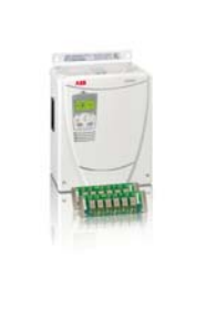
 ABB ACS6000 medium voltage frequency converter
 -
 OMRON NX502 model Sysmac platform machine controller hardware usage instructions

K-JIANG

Add: Jimei North Road, Jimei District, Xiamen, Fujian, China
Tell:+86-15305925923