K-WANG

+086-15305925923
Service expert in industrial control field!
NameDescriptionContent
Adequate Inventory, Timely Service
pursuit of excellence 
Ship control system
Equipment control system
Power monitoring system
Current position:
   
Brand
Honeywell Low VoltageTerminal Block (Barrier Style) Note 3 900TBK-0101
❤ Add to collection

Honeywell Low VoltageTerminal Block (Barrier Style) Note 3 900TBK-0101

+86-15305925923
Mr.Wang
wang@kongjiangauto.com

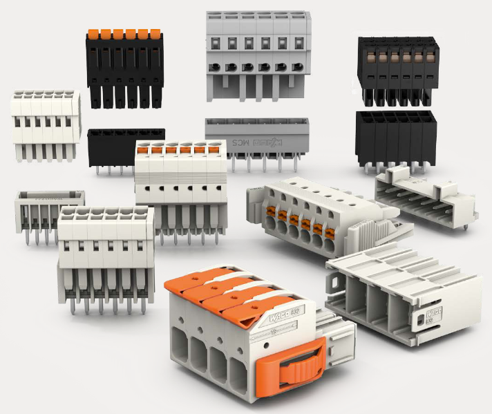
Each I/O module includes a status indicator for the module. Digital Input and Digital Output modules also

include a status indicator for each channel. Terminal blocks available include the Euro style (Error!

Reference source not found. left) and the Barrier style (Error! Reference source not found. right).

18000.00
¥18000.00
Weight:3.550KG
Quantity:
(Inventory: 18)
Consultation
Accessories
  • ABB-07AC91-Analo
    Original :¥16475.00
    With a price :¥16475
    Quantity  
  • ABB-AC31 91serie
    Original :¥16475.00
    With a price :¥16475
    Quantity  
  •   
    Original :¥
    0.00
      
      With the total price :¥
    0.00
Product parameters
  • Telephone:+86-15305925923
  • contacts:Mr.Wang
  • Email:wang@kongjiangauto.com
Description

Each I/O module includes a status indicator for the module. Digital Input and Digital Output modules also

include a status indicator for each channel. Terminal blocks available include the Euro style (Error!

Reference source not found. left) and the Barrier style (Error! Reference source not found. right).


Honeywell Low VoltageTerminal Block (Barrier Style) Note 3 900TBK-0101

Each I/O module includes a status indicator for the module. Digital Input and Digital Output modules also
include a status indicator for each channel. Terminal blocks available include the Euro style (Error!
Reference source not found. left) and the Barrier style (Error! Reference source not found. right).
For more information on I/O modules and associated terminal blocks, refer to the section in this manual on
Input/Output Installation and Wiring.
Personal Computer
A Personal Computer is required to create the control and data acquisition strategy (configuration file) that
runs in the controller, using the Designer configuration software. The PC can also be used to
download/upload configuration files to/from the controller, and can be used to download program updates
to firmware in the Controller Module and/or Scanner Modules.
 A PC can be connected to the controller via the RS-232 port for legacy system.
 For the new system, a PC can be connected to the controller via the RS-485 to USB cable connected to
RS485 Port , which can be connected to external Honeywell qualified RS485 to USB converter, and can
also be networked to the controller via the Ethernet 10/100Base-T Open Connectivity Network port.
Redundant controllers: PC communicates with Lead Controller only.
NOTE: For specific PC requirements and for specific software requirements, refer to the Designer Software
Users Manual.
RS-232 Modem Devices
In Legacy systems the PC configuration tool can connect from the RS-232 serial port of the Controller
Module to a serial port on the PC.
For new system, the PC Configuration tool connects to the galvanically isolated RS-485 port on the
Controller Module using an external Honeywell qualified RS-485 to USB converter.
The PC can be located remote from the Controller by using Modems and telephone links. Modems and

suitable cabling are available from third-party vendors.
Figure 18 – HC900 Controller Configurations

In any of the racks shown in each controller configuration can be 4-, 8-, or 12-slot versions.
The Ethernet cables for the I/O expansion links are standard shielded Cat 5 cables, with standard RJ45
connectors. Each cable segment can be up to 100 meters (328 feet) long.
You can also use fiber optic cable for connections between the controller and a remote rack. Please refer to
HC900 specification document (51-52-03-31) for more details.
Configuration 1 is the C30/C30S/C50/C50S/C70/C70S CPU with I/O but no I/O expansion racks.
Configuration 2 shows the C50/C50S/C70/C70S CPU with 1 I/O expansion rack. The Ethernet cable
connects directly between the 10/100 Base-T connectors on the C50/C70 CPU Controller Module and the
Scanner Module.
ATTENTION:
For 2 or more I/O expansion racks a switch is required. Use only Honeywell recommended switches
(part no. 50008930-001, 50089785-001). The total number of switches is limited to 2 in series between
a CPU and its scanners.
Configuration 3 shows the C50/C50S/C70/C70S CPU with 3 I/O expansion racks. Since there are at least 2
I/O expansion racks a switch is required. When an Ethernet switch is used to connect to expansion I/O, a
cable goes between the I/O port on the controller to the switch. Two cables go from the switch to 2
scanners. A third cable goes from the switch to a second switch, which connects to a third remote scanner.

I/O implementation requirements include:
 Constructing a configuration file, and loading it into the Controller Module. This file includes I/O
numbering assignments for each I/O Function Block regarding Rack Number, Module Number ("slot"
number, or position in the rack, starting from the left), and Channel Number.
 Physically assigning Rack Numbers, by positioning DIP switch settings in the Scanner Module for each
rack.
 Placing the appropriate module type in each slot in each rack.
The I/O expansion network uses Honeywell private protocol that optimizes I/O performance and security.
The configuration and operation of the I/O expansion network is automatic, it is entirely under control of
built-in private software that resides in the Controller Module and in each Scanner Module included in the
HC900 system. The controller examines the control strategy stored in its memory, verifies that the physical
configuration (Rack Numbers and I/O Module type- by Module Number) matches the stored control
strategy, and establishes communication with each of the I/O modules in each of the I/O racks.
I/O Expansion Network (C75 /C75S)
I/O for redundant controllers is the same as I/O Expansion Network page 33, with the following
exceptions/notes.
 In Figure 18, any of the racks shown in each controller configuration can be 4-, 8- or 12-slot versions.
Redundant I/O power not available with 4-slot.
 Double the amount of Switches and Ethernet cables are required to configure the redundant I/O Link.
 Maximum of 2 switches between each CPU (CPU A and CPU B) and the I/O racks.
Ethernet Open Connectivity Network
The configuration of the Ethernet Open Connectivity Network varies with specific applications in purpose
and in complexity. In some applications, configuration is straightforward and within the capabilities of
experienced installation technicians. In other applications (for example, those that include inter-connection
to other networks such as Intranet and Internet), a working knowledge of networking is required.
The Ethernet Open Connectivity Network for a given HC900 Controller enables:
 Redundant Networks.
 Peer-to-peer communication (Safety peer communication for SIL controller from release 6.300)
 Connection to other PC hosts
 Inter-connection to other networks (such as for sending Alarm/Event messages via e-mail.)
 These ports are to be considered part of the control network layer and as such care must be taken to
reduce exposure to uncontrolled network influences. A properly configured firewall such as the
MOXA EDR-810 is recommended to help mitigate.
CAUTION
Communications lockout is possible in high network traffic conditions.
Extraneous traffic is possible when sharing bandwidth with other devices. We recommend putting the
controller on a private network segment. Failure to do so could, in high traffic cases, result in
communications lockout requiring the controller to be power-cycled.
  • TRICON ®/ Installation and maintenance of E/E2/E3 transmitters
  • TRLC0NEX Tricon fault-tolerant controller
  • WAGO 221 series LEVER-NUTS ® Compact splicing connector
  • WAGO-I/O-SYSTEM 750 Programmable Fieldbus Controller ETHERNET 
  • WAGO Rail-Mount Terminal Blocks with Screw and Stud Connection
  • WAGO series molded case circuit breaker (MCCB)
  • WAGO Rail-Mount Terminal Blocks
  • WAGO I/O System 750/753 Series Distributed Automation System
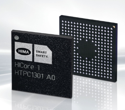
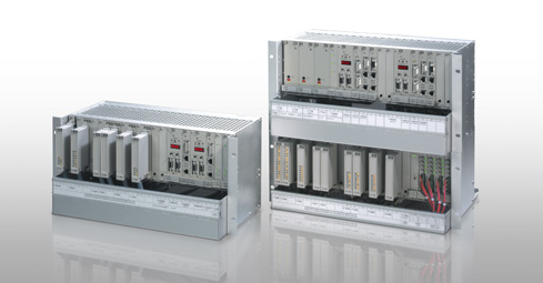
  • HIMA X-CPU 01 processor module
  • Westinghouse iGen5000 Digital Inverter Generator
  • Westinghouse WGen7500DF Dual Fuel Portable Generator
  • Westinghouse WPX2700H/WPX3100H High Pressure Cleaning Machine
  • Westinghouse WH7500V portable generator
  • Westinghouse WGen9500c portable generator
  • Westinghouse DS/DSL series low-voltage power circuit breakers
  • Westinghouse ePX3500 Electric High Voltage Cleaning Machine
  • Westinghouse ST Switch Intelligent Automatic Portable Transfer Switch
  • Westinghouse 2400i digital inverter generator
  • Westinghouse iGen series digital inverter generator
  • HIMA CPU 01 Controller Module
  • Westinghouse WPX3000e/WPX3400e electric high-pressure cleaning machine
  • Westinghouse WGen2000, WGen3600, and WGen3600V portable generators
  • Westinghouse WGen5500 Generator
  • Westinghouse WGen20000 Generator
  • Westinghouse WPro8500 and WPro12000 portable generators
  • Westinghouse iGen4500DFc Dual Fuel Digital Variable Frequency Generator
  • Watlow Series L Temperature Limiting Controller
  • Watlow Series F4P Series 1/4 DIN (96 × 96mm) Temperature/Process Controller
  • Watlow EZ-ZONE ® RME (Expansion) Module
  • Watlow EZ-ZONE ® RMA (Access) module
  • Watlow PM PLUS ™ 6 Series PID Integrated Controller
  • Watlow Immersion Heater
  • Watlow F4T Controller Installation and Failure
  • Watlow DIN-A-MITE ® Style C Solid State Power Controller
  • Watlow plug-in heater
  • Watlow Series 942 Controller
  • Watlow Series 988 Controller
  • Watlow Series 146 Temperature Regulator
  • Watlow PM LEGACY ™ Limit controller
  • Johnson AE55/NIE55 Installation Guide
  • Watlow Series 96 Temperature Controller
  • Watlow PM PLUS ™ PID/Integrated Limit Controller
  • Watlow Ceramic Fiber Heater
  • Watlow Power Series microprocessor based SCR power controller
  • Watlow thermocouple products
  • Watlow Series 965 Controller
  • Watlow PM3 LEGACY ™ PID controller
  • Watlow Series 93 Controller
  • Watlow EZ-ZONE ® PM PID controller
  • Watlow CLS200 series controller
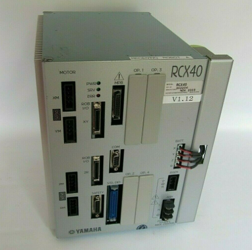
  • YAMAHA RCX40 4-axis robot controller
  • YASKAWA Z1000 series HVAC dedicated frequency converter
  • YASKAWA HV600&Z1000U series HVAC dedicated frequency converter
  • YASKAWA Power Regenerative Unit R1000 Series
  • YASKAWA AC Drive P1000 Industrial Fan and Pump Special Frequency Converter
  • YASKAWA FP605 series industrial fan pump dedicated driver
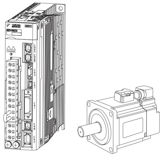
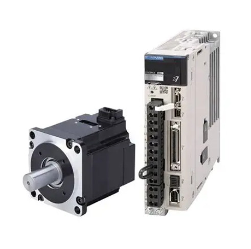
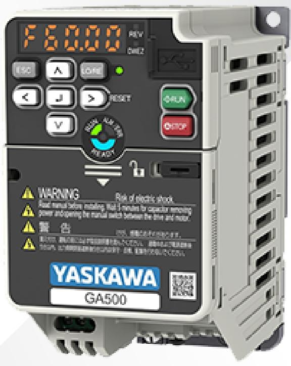
  • YASKAWA GA500 series AC micro driver
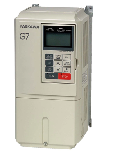
  • YASKAWA AC Drive G7 Series (Model CIMR-G7U)
  • YASKAWA U1000 series 24V power supply options (PS-U10L/PS-U10H)
  • YASKAWA GA800 industrial AC frequency converter Key issues
  • YASKAWA GA800 Industrial AC Inverter
  • YASKAWA AC Drive V1000 Compact Vector Control Drive
  • YASKAWA Control Pack CP-317M System Controller
  • YASKAWA VARISPEED-626M/656MR5 series vector control frequency converter
  • YASKAWA AC Servo Drive HR Series (CACR-HR) Multi functional/Positioning Control
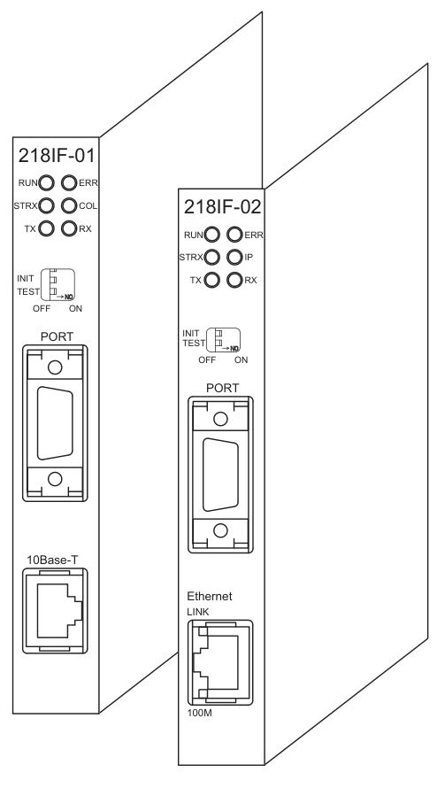
  • YASKAWA MP2000 series machine controller communication module
  • Yokogawa AQ1100 series OLTS multi field tester
  • YOKOGAWA AQ7280 Optical Time Domain Reflectometer
  • YOKOGAWA AQ2200 Series Multi Application Testing System
  • YOKOGAWA AQ6150B/AQ6151B Optical Wavelength Meter
  • YOKOGAWA AQ6360 Optical Spectrum Analyzer
  • Yokogawa AQ6375E Spectral Analyzer Remote Control
  • Yokogawa DL350 Scope Order Communication Interface
  • Yokogawa 701944/701945 100:1 High Voltage Probe
  • Yokogawa CA700 pressure calibrator
  • Yokogawa DLM5000HD series high-definition oscilloscope
  • Yokogawa AQ1210 Series OTDR Multi Field Tester
  • Yokogawa AQ1000 OTDR Optical Time Domain Reflectometer
  • YOKOGAWA WT1801R series precision power analyzer communication interface
  • YOKOGAWA DLM3034HD/DLM3054HD High Definition Oscilloscope
  • YOKOGAWA AQ23011A/AQ23012A Modular Framework Equipment
  • YOKOGAWA DLM3054HD Mixed Signal Oscilloscope
  • YOKOGAWA CW500 Power Quality Analyzer
  • YOKOGAWA CA500/CA550 Multi functional Process Calibration Instrument
  • YOKOGAWA AQ7420 High-Resolution Reflectometer
  • YOKOGAWA FG410/FG420 arbitrary waveform editor
  • Yokogawa Model 701905 Conversion Cable
  • YOKOGAWA MY600 Digital Insulation Resistance Tester
  • YOKOGAWA AQ7290 Series Optical Time Domain Reflectometer OTDR
  • YOKOGAWA LS3300 AC Power Calibrator
  • Yokogawa AQ6377E Optical Spectrum Analyzer Remote Control
  • Yokogawa AQ6361 Optical Spectrum Analyzer
  • Yokogawa IS8000 Integrated Software ECU Monitoring and Synchronization Function
  • Yokogawa ROTAMASS TI Coriolis Mass Flow Meter
  • Yokogawa ROTOMETER RAMC Metal Variable Area Flow Meter
  • Yokogawa SL1000 high-speed data acquisition unit input module
  • ​Yokogawa FLXA402T turbidity and chlorine liquid analyzer Installation and wiring
  • Yokogawa WTB10-DO Series Dissolved Oxygen Measurement System Terminal Box
  • Yokogawa Model 702928 PBD0200 Differential Probe
  • YOKOGAWA ADMAG TI Series AXW Electromagnetic Flow Meter (25-450mm) Installation and Operation
  • YOKOGAWA ADMAG TI series AXW electromagnetic flowmeter (25-1800mm)
  • YOKOGAWA DO30G Dissolved Oxygen Sensor
  • YOKOGAWA SC4AJ Conductivity Sensor
  • YOKOGAWA SC210G Conductivity Detector
  • Yokogawa PH4/OR4 series pH and ORP sensor (IM12B10B00-01EN)
  • Yokogawa OR8EFG KCl filled ORP sensor (IM12C07J01-01E)
  • YOKOGAWA FU24 pH/ORP Composite Sensor with Pressure Compensation (IM 12B06J03-03EN-P)
  • Yokogawa SC200 Intelligent Two Wire Conductivity Transmitter System (IM12D08B01-01E)
  • YOKOGAWA CENTUM VP Integrated Production Control System (TI33J01A10-01EN)
  • ABB AO2000-LS25 Laser Analysts User Manual
  • YOKOGAWA FA-M3 positioning module (with analog voltage output)
  • YOKOGAWA FA-M3 Series Basic Modules
  • YOKOGAWA EJA110E Diff erential Pressure Transmitter
  • Zygo 3D Optical Profiler
  • Zygo Mark II 4-inch interferometer system
  • Zygo NewView 9000 3D Optical Contour Analyzer Core Features
  • Zygo NewView 9000 3D Optical Profilometer Technology
  • Zygo Profilometer Standard Operating Procedure
  • Zygo’s Guide to Typical Interferometer Setups
  • ZYGO Laser Interferometer Accessory Guide OMP-0463AM
  • ZYGO MetroPro 9.0 Reference Guide (OMP-0347M)
  • Zygo Device Standard Operating Procedure (SOP)
  • Zygo Verify Laser Interferometer
  • Zygo MicroLUPI interferometer
  • ZYGO ZMI-1000 Displacement Measuring Interferometer System
  • Zygo's ZMI 2000 displacement measurement interferometer system
  • ABB IGCT Technology: A Revolutionary Breakthrough in High Voltage Inverters
  • Siemens 6AG1204-2BB10-4AA3 Ethernet Switch