
K-WANG
+086-15305925923
Service expert in industrial control field!
Product
Article
NameDescriptionContent
Adequate Inventory, Timely Service
pursuit of excellence


Ship control system
Equipment control system
Power monitoring system
Brand
Product parameters
- Telephone:+86-15305925923
- contacts:Mr.Wang
- Email:wang@kongjiangauto.com
Description
NOTE: The 15" control station can be programmed using only the Ethernet, serial and compact flash card.
The 900CS15's USB programming port conflicts with today’s PCs so it's advisable to use Ethernet ports for
configuration changes. This problem has been observed only with the 15" control station; the 10" control
station has not shown any problems with its USB ports.
Honeywell Redundant Power Status Module 900PSM-0101
NOTE: The 15" control station can be programmed using only the Ethernet, serial and compact flash card.
The 900CS15's USB programming port conflicts with today’s PCs so it's advisable to use Ethernet ports for
configuration changes. This problem has been observed only with the 15" control station; the 10" control
station has not shown any problems with its USB ports.
Serial Port S1/S2
The Serial Port S1 and Serial Port S2 screens both show Statistics (Table 6) and Settings (Table 8) for those
controller serial ports.
Table 9 shows the relationship between the setup parameters and each protocol.
The controller’s Serial Port S1 can be set-up as an ELN Configuration port, a Modbus Master port, or a
Modbus Slave port. The ELN protocol allows the controller to communicate with the Process Control
Designer package on the PC using the proprietary ELN protocol. The Modbus Master protocols allow the
controller to act as a Modbus Master, retrieving data from other instruments that have been configured as
Modbus slave devices. The three Modbus Slave protocols allow the controller to act as a slave to various
host devices, including a PC running HC Designer.
The information presented in Table 6 and Table 9 also applies to Serial Port S1 when a Redundant
Controller is used.
Table 6 Serial Port S1/S2 Statistics (left side of display)
Item Description
Port Diagnostic Shows the overall condition of the Serial Port S1. See the list of Serial Port S1
diagnostic conditions in Table 7 on page 24.
Port Status This is the current status of the port. The possible status conditions are:
GOOD: the protocol is set to ELN.
REQUIRES SETUP: the protocol is set to one of the Modbus Slave protocols, and
the Slave Address is set to 255. Messages on the communication link are ignored
in this state.
OFFLINE: the protocol is set to one of the Modbus Slave protocols, and the Slave
Port Enable is set to DISABLE. Messages on the communication link are ignored
in this state.
ONLINE: the protocol is set to one of the Modbus Slave protocols, and the Slave
Port Enable is set to ENABLE. Messages on the communication link are being
processed in this state.
NO MODBUS SLAVE BLOCKS: the protocol is set to one of the Modbus Slave
protocols, but there are no Modbus slave function blocks present in the controller’s
configuration.
PROGRAM MODE: the protocol is set to one of the Modbus Slave protocols, but
the controller is in Program Mode. The controller does not scan the slave devices in
this state.
ELN SLAVE: the protocol is set to one of the Modbus Slave protocols, but the
controller is in Program Locked Mode. The port automatically reverts to ELN
protocol and the controller becomes a slave device whenever the mode selection
switch is placed in the Program Locked position.
SCANNING SLAVES: the protocol is set to one of the Modbus Slave protocols, and
the controller is actively scanning the slave devices attached to the port.
Messages Received The number of messages that were received and processed correctly.
Data Link Errors The number of basic link-level errors detected by the controller. If the protocol is
Modbus Master, the errors may be due to a slave device that does not reply when it
is scanned. Refer to the section “Troubleshooting Data Link Errors” (page 35) for
more information.
Application Errors The number of messages that were responded to with an exception code. For
example, application errors can be caused by (a) writing to a read-only register, (b)
accessing a register that is not supported by the slave device, or (c) using a
Modbus function code that is not supported by the slave device.
Clear Statistics This item resets the message counters for this port back to zero (Messages
Received, Data Link Errors, and Application Errors). Note: the counters will only be
reset if the controller is in Run Mode.
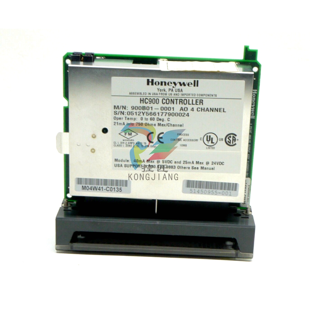
Table 7 Serial Port S1/S2: Port Diagnostic status
Status Possible Cause Controller Action What to do
GOOD N/A N/A N/A
APPLICATION
ERROR
Applies to Port S2
only. At least one
response to a host
resulted in an
exception code or
NAK.
1. Rack 1 monitor block’s
COMPORT DIAG is set to
WARNING.
2. Rack 1 monitor block’s
RACK OK pin is turned off.
3. SYSTEM MONITOR
block’s HW OK pin is
turned off.
At host, determine which message is
causing the exception code and fix it.
DATA LINK
ERROR
A large number of
messages are
resulting in data link
errors.
1. Rack 1 monitor block’s
COMPORT DIAG is set to
FAILED.
2. Rack 1 monitor block’s
RACK OK pin is turned off.
3. SYSTEM MONITOR
block’s HW OK pin is
turned off.
4. If configured as Modbus
Master port, associated
slave blocks have their
read pin values frozen to
the last value read.
1. Check baud rate.
2. Check connectors.
3. Check cable polarity.
4. Isolate cable from electrical
interference.
5. If RS232-to-RS485 converter used,
check its power, switch/jumper settings,
and polarity.
HARDWARE
FAILURE
The DUART is failing
to operate properly.
Replace the controller CPU module.
Table 8 Serial Port S1/S2 Settings (right side of display)
Setting Description
Protocol ELN: The default protocol, used to communicate with the HC Designer
configuration software.
MODBUS MASTER: The controller acts as a Modbus Master device on the
communication link.
MB MASTER ADVANCED: The controller acts as a Modbus Master device on the
communication link. This protocol provides enhanced data throughput for
applications where the HC900 is being used with a “Modbus-to-fieldbus” gateway device.
MODBUS SLAVE MULTI: The controller acts as a Modbus Slave device. This
protocol allows more than one slave device to be present on the communications
link (multi-drop).
MODBUS SLAVE PTP: The controller acts as a Modbus Slave device. This
protocol can be used if the controller is the only slave device on the link (Point-to point).
MODBUS SLAVE MODEM: The controller acts as a Modbus Slave device. This
protocol provides the extended delays that are needed to access the controller via
a modem.
Baud Rate (Bps) Select 9600, 19200, 38400, 57600 or 115200 bits per second.
Modbus Parity Select None, Odd, or Even parity.
Modbus Stop Bits Select 1 or 2 Stop Bits.
Slave Address (1-247 or 255)
This is the address of the controller on the Modbus link when one of the three
Modbus Slave protocols is selected. All devices on the link must have a unique
Modbus address. The address may be set to a value of 1 to 247, or it may be set
to 255. A value of 255 disables the port for this controller.
Slave Port Enable This item allows you to enable or disable the port:
ENABLE: The port will respond to communication requests.
DISABLE: The port will ignore communication requests.
Double Register Format Under the Modbus protocol, each IEEE 32-bit floating-point number requires two
consecutive Modbus registers, for a total of four bytes. The stuffing order of the
bytes within these registers differs among Modbus devices. To provide
compatibility with the various hosts, the double-register format is configurable. The
selections are:
FP B Big Endian format Byte order: 4, 3, 2, 1
FP L Little Endian format Byte order: 1, 2, 3, 4
FP BB Big Endian with byte-swap Byte order: 3, 4, 1, 2
FP LB Little Endian with byte-swap Byte order: 2, 1, 4, 3
Purchase history
| User name | Member Level | Quantity | Specification | Purchase Date |
|---|
Total 0 Record
Related products
Customer Reviews
Satisfaction :
5 Stars
No evaluation information


KONG JIANG


Add: Jimei North Road, Jimei District, Xiamen, Fujian, China
Tell:+86-15305925923


