
K-WANG
+086-15305925923
Service expert in industrial control field!


Product
Article
NameDescriptionContent
Adequate Inventory, Timely Service
pursuit of excellence


Ship control system
Equipment control system
Power monitoring system
Brand
Description
Items covered by delivery
Delivery typically comprises the following items:
- Drive that is shipped in sea freight or airfreight packaging.
- Optional components and cabinets
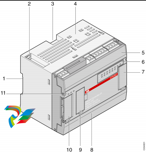
- Set of door keys attached to lifting rail (1 in Fig. 1-1)
- Set of door keys inside the drive
- Rating label (2 in Fig. 1-1)
- Box with USB stick (3 in Fig. 1-1), which contains the user manual and related documents.
- Strain relief rails
- Air exhaust hood
- Redundant fan unit (option)
- Set of bolts, nuts and washers
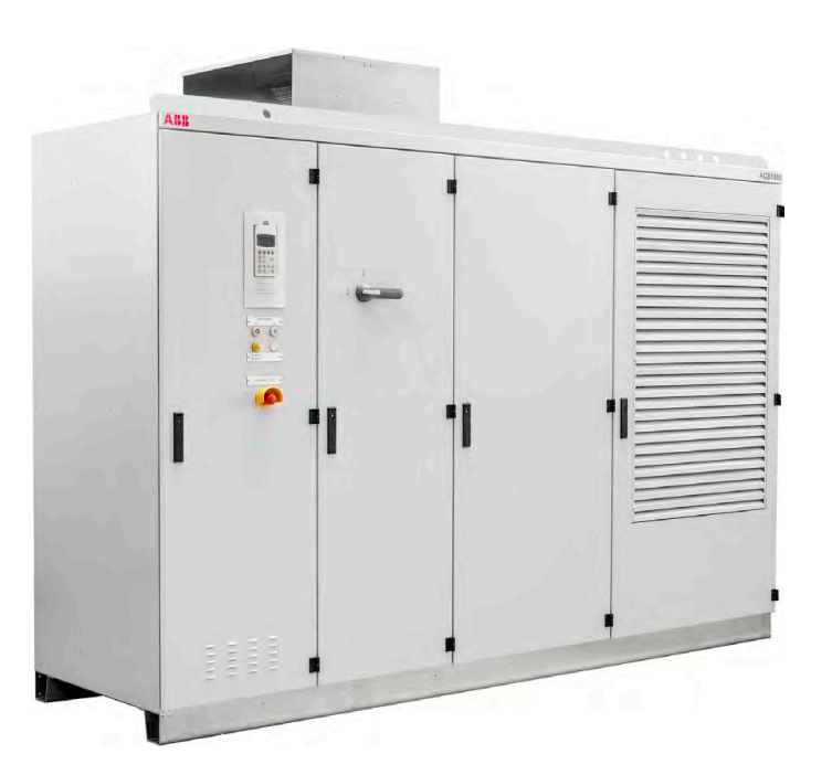
ABB ACS1000 air-cooled
OverviewRead this material before working on or around the equipment. Failure
to do so can result in injury or death!
2.1.1 Safety standards
The following industry standards are observed:
- "ANSI Z535.6 American national standard for product safety information in product
manuals, instructions, and other collateral materials" [16]
- "ISO 3864-2:2004 (E) - Graphical symbols – Safety colors and safety signs – Part 2: Design
principles for product safety labels" [17]
- "ISO 7010:2011 (E) - Graphical symbols - Safety colours and safety signs - Registered
safety sign" [18]
- "EN 50110 European standard code for electrical work safety" [19]
2.2 Safety messages
The following safety messages are provided to help prevent personal injury and damage to the
equipment. The indicated hazard level is based on the ANSI Z535.6 standard.
Product safety labels
Safety labels are affixed to the drive components to alert personnel of potential hazards when
working on the equipment. For more information, see the label placement document for
the drive.
The instructions on the safety labels must always be followed and the labels must be kept in a
perfectly legible condition.
Figure 2-1: Product warning label examples (label placement depends on the drive)
Additional safety labels, including the following, might also be provided:
(1) Danger label
(2) Caution label
(3) Warning label
(4) Notice label
Electricity hazard
This sign can also have additional text below it, eg, “High voltage”
Hot surface
Crushing of hands
No access for people with active implanted cardiac device
The magnetic field of the drive can influence the functioning of pacemakers. The
pacemaker sign should be installed at the entrance to the drive room or at a
minimum distance of 6 m from the drive to stop personnel with pacemakers
approaching the drive.
Firefighting sign
Outlines the procedure when fighting fire in electrical equipment. The sign must
be installed well visible near the drive.
High voltage sign
Must be installed clearly visible at the main circuit breaker in the switchgear room.
The sign alerts personnel to the high voltage which can be present on the
secondary side of the input transformer until the main circuit breaker has been
opened and secured and the drive has been de-energized and grounded.
General safety instructions
Minimize hazards
- Always observe local safety laws and regulations when working with electricity.
Before energizing the drive:
- Remove all foreign objects are from the drive
- Fasten all internal and external covers securely
- Close, lock, and/or bolt all doors
- Move the release dial of the door safety switches into the locked position
Before working on the drive:
- Turn off, lock out, and tag out the main and auxiliary power supplies to
the drive
- De-energize the drive
- Ensure that the safety ground connections are in place
- Ensure that the appropriate personal protective equipment (PPE) is available
and used when required
- Inform the involved personnel about the potential safety hazards
- Wear hearing protection when a drive is running.
Before working simultaneously on the drive and on other drive
system equipment:
- Observe the relevant safety codes and standards
- Turn off all energy sources for the equipment
- Ensure that all lockout and tagout devices are in place
- Install barriers around and use appropriate covers on the equipment that is
still energized
- Inform the involved personnel about the potential safety hazards
In case of fire in the drive room:
- Observe the established rules and regulations for fire safety
- Only allow firefighters with the appropriate PPE to enter the drive room
02 IMPORTANT SAFETY INFORMATION
3BHS213401 E01 REV H ACS1000 AIR-COOLED USER MANUAL 20/184
2.6 The 7 steps that save lives
ABB’s 7 steps that save lives concept is a series of actions that must take place prior to
commencing work on or near electrical installations. Everyone in the working party must be
fully engaged in this process to place electrical installations in a safe working condition and is
empowered to speak out if there are any deviations in this process and refuse to proceed until
these steps are carried out in their entirety.
1 Prepare for the work: do an on-site risk assessment or job
hazard analysis that considers the limits of approach for
shock and arc-flash.
- Be in possession of a clear work order to execute the work.
- When required, the access or work permit is to be obtained by a person
who is authorized for the specific electrical system.
- Engage the person responsible for electrical equipment or system to
review single-line diagrams, schematics, switching plans, etc.
- Ensure the competence of workers.
- Check for proper tools for the job.
- Determine and select the proper arc-rated Personal Protective
Equipment (PPE).
- Decide of the appropriate work methods and initiate the
- Permit To Work (PTW) process.
2 Clearly identify the work location and equipment.
- Use your senses (sight, hearing and smell) to identify problem areas.
- Define the work area via barriers and barricading and label equipment.
- Avoid distractions such as talking or texting on the phone.
3a Disconnect all sources of supply.
- If ABB is responsible for switching and it cannot be done remotely, then
the person performing the switching must be properly trained and
wearing the proper PPE identified in step 1.
- The Person in Charge of Work (PICW) must ensure that switching is
performed in the proper manner by witnessing it from a safe distance if
present on site or by engaging the person responsible for switching to
identify all isolation points.
3b Secure against reconnection by applying Lockout/Tagout.
- Apply Lockout/Tagout (LOTO) to the energy isolation device and if
multiple energy isolation devices are involved, then Group LOTO must
be implemented with the PICW serving as the Group LOTO Leader.
Purchase history
| User name | Member Level | Quantity | Specification | Purchase Date |
|---|
Total 0 Record
Related products

Customer Reviews
Satisfaction :
5 Stars
No evaluation information


- other
- LTI Drives
- ADLINK
- Beckhoff
- Other Brands
- AMAT
- Iba
- PEPPERL+FUCHS
- Aerotech
- WATLOW
- MAN
- ADVANCED
- Abaco
- YOKOGAWA
- KOLLMORGEN
- MEGGITT
- kong-sberg
- METSO
- Motorola
- NI
- OEMAX
- RELIANCE
- scanlab
- schneider
- uniop
- Vibro-Meter
- Honeywell
- Rolls-Royce
- MOOG
- GE
- B&R
- Woodward
- Yaskawa
- xYCOM
- Siemens
- Emerson
- HIMA
- Bently
- ZYGO
- FOXBORO
- OMACO
- PROSOFT
- ENTERASYS
- TRICONEX
- Parker
- Lenze
- KEBA
- Alstom
- CTI
- ABB
- A-B
172

-
 ADLINK PCI-9112/cPCI-9112 multifunctional acquisition card
 -
 ADLINK PCI-8102 Two Axis Pulse Motion Control Card
 -
 ADLINK PCI-9812/PCI-9810 synchronous 4-channel high-speed acquisition card
 -
 ADLINK PCI-7200/cPCI-7200 high-speed digital I/O board
 -
 ADLINK MXE-1000 series fanless embedded machine
 -
 ADLINK IMB-T10 Mini ITX Industrial Motherboard
 -
 ADLINK HSL Distributed High Speed I/O System
 -
 ADLINK PXI/DAQ/DAQe-2500 series multifunctional analog output DAQ card
 -
 ADLINK PXI/DAQ/DAQe-2200 series multifunctional data acquisition card
 -
 ADLINK ETX-AT ETX Core Computer Module
 -
 ADLINK ACL-7225 ISA 16 channel relay output+16 channel isolated digital input card
 -
 ADLINK DAQ-2000 series synchronous acquisition card
 -
 ADLINK NuPRO-E330 PICMG 1.3 full-length industrial motherboard (SHB)
 -
 ADLINK ACL-8112 series multifunctional ISA acquisition card
 -
 ADLINK USB-2405 24 bit dynamic signal acquisition module
 -
 ADLINK PXIS-3320 15 slot 6U PXI chassis
 -
 ADLINK PCIe GIE7x series acquisition card
 -
 ADLINK PCIe-7856/PCIe-7853 Distributed Motion and IO Main Controller PCIe Acquisition Card
 -
 ADLINK PCI-6308 series isolated analog output board
 -
 ADLINK PCI-7432 Isolated Digital I/O Acquisition Card
 -
 ADLINK NuPRO-E72 PICMG 1.3 Full length Industrial SHB Single Board Computer
 -
 ADLINK MXE-5400 series fanless embedded industrial computer
 -
 ADLINK M-322 Industrial ATX Motherboard
 -
 ADLINK IMB-M43H Industrial ATX Motherboard
 -
 ADLINK IMB-M42H Industrial ATX Motherboard
 -
 ADLINK i915GV-INA ATX motherboard
 -
 ADLINK ETX-NR667 Embedded ETX Standard Computer Module
 -
 ADLINK ETX-BT (PATA to SATA version) User Manual
 -
 ADLINK CM1-BT1 PC/104 Single Board Computer
 -
![ADLINK cPCI-8217 [R] 3U CompactPCI VGA/LCD Display Module](https://aosspic10001.websiteonline.cn/hkw632bc8/image/image_aJXQRn.png) ADLINK cPCI-8217 [R] 3U CompactPCI VGA/LCD Display Module
ADLINK cPCI-8217 [R] 3U CompactPCI VGA/LCD Display Module -
 ADLINK AmITX-SL-G Mini ITX Embedded Motherboard
 -
 ADLINK AmITX-AL-I ultra-thin Mini ITX industrial motherboard
 -
 ADLINK NuPRO-E315 Full length PICMG 1.3 Industrial SHB Single Board Computer
 -
 ADLINK NuPRO-842 Full length PICMG 1.0 PCI/ISA Industrial Single Board Computer
 -
 ADLINK NuPRO-900A PICMG 1.2 ePCI-X Dual Xeon Industrial System Motherboard (SHB)
 -
 ADLINK cPCI-6910 series 6U CompactPCI single board computer
 -
 ADLINK cPCI-6860A 6U CompactPCI dual core single board computer with cPCI-R6860A rear adapter board
 -
 ADLINK cPCI-8168 6U CompactPCI Eight Axis Motion Control Card
 -
 ADLINK NuPRO-E340 PICMG 1.3 Industrial SHB motherboard
 -
 ADLINK NuPRO-A40H Full length PICMG1.0 Industrial Single Board Computer (SBC)
 -
 ADLINK NuPRO-852 Full length PICMG1.0 Industrial Single Board Computer
 -
 ADLINK NuPRO-841 Full length Industrial SBC
 -
 ADLINK NuPRO-590/591/592 series Socket7 full-length industrial SBC
 -
 ADLINK MXE-5500 series fanless embedded industrial computer
 -
 ADLINK MXE-200/200i Fanless Embedded Machine
 -
 ADLINK cPCI-6770 series CompactPCI CPU board
 -
 ADLINK NuPRO-A301 standard PICMG 1.0 full-length industrial SBC single board computer
 -
 ADLINK NuPRO-965 PICMG 1.3 SHB Express Full length Industrial Motherboard
 -
 ADLINK NuPRO-935A Full length PICMG1.0 Industrial Single Board Computer
 -
 ADLINK NuPRO-865 Full length Single Board Computer
 -
 ADLINK NuPRO-840 DV/LV Full Length PICMG Industrial Single Board Computer
 -
 ADLINK NuPRO-770 series full-length industrial single board computer
 -
 ADLINK NuPRO-595 series half length Socket 7 industrial motherboard
 -
 ADLINK cPCI-6840 series 6U CompactPCI single board computer
 -
 Foxboro 43AP series pneumatic indicator controller (PSS 3-1B3 A)
 -
 ADLINK cPCI-3720 Series 3U Low Power CompactPCI Single Board Computer
 -
 ADLINK NuPRO-E47, PICMG 1.3 full-length industrial SHB system motherboard
 -
 ADLINK NuPRO-E43 PICMG 1.3 full-length system motherboard
 -
 ADLINK NuPRO-780 series full-length industrial CPU board
 -
 ADLINK cPCI-6965 series 6U CPCI single board computer
 -
 ADLINK USB/LPCI/LPCIe-3488A GPIB interface card
 -
 Rittal SK 3241.700 Blue e+Fan Filter Unit
 -
 ADLINK cPCI-8168 6U CompactPCI 8-Axis Motion Control Card
 -
 ADLINK PCIe PXIe-8638 PCIe to PXIe Bus Expansion Kit
 -
 ADLINK PCIe GIE7x series acquisition card
 -
 ADLINK PCIe-7396 96 96 channel TTL digital IO card
 -
 ADLINK PCI/MPC/PXI-8164 Three in One Motion Control Card
 -
 ADLINK PCI-8154 Four Axis Pulse Motion Control Card
 -
 ADLINK PCI-8134 Four Axis Servo/Stepper Motion Control Card
 -
 ADLINK NuPRO-E42 PICMG1.3 full-length SHB motherboard
 -
 ADLINK MXC-6600 series high-performance fanless extended industrial computer
 -
 ADLINK MXC-6000 series embedded industrial control computer
 -
 ADLINK MXC-2300 series fanless expandable embedded industrial computer
 -
 ADLINK MCM-204 Independent Ethernet DAQ User Manual
 -
 ADLINK MCM-100/102 Edge IoT Platform for Machine Condition Monitoring User’s Manual
 -
 ADLINK MXC-6400 series sixth generation Core Fanless Scalable Industrial Control Computer
 -
 ADLINK Matrix Full Series Fanless Embedded Industrial Control Computers
 -
 ADLINK GIE64+4-channel PoE Gigabit Vision Capture Card
 -
 Honeywell UMS Security System Troubleshooting Guide
 -
 Honeywell Expert Series-C I/O Module
 -
 ADLINK EOS-1200 Embedded Vision Host
 -
 ADLINK DLAP-5200 series high-performance fanless AI industrial computer
 -
 ADLINK DLAP-4000 series embedded industrial control computer
 -
 ADLINK Matrix MXC-2000 Series Fanless Industrial Control Computer Specification
 -
 ADLINK DAQ -/DAQE -/PXI-2000 Series Multi functional Synchronous Acquisition Card
 -
 ADLINK cPCI-6520 6U CompactPCI Single Board Computer
 -
 ADLINK CM1-86DX3 PC/104 Single Board Computer
 -
 Honeywell DC1000 series PID temperature controller
 -
 ALSTOM MiCOM C264 Modular Substation Controller
 -
 EMERSON AMS 2140 Mechanical Health Analyzer
 -
 ADLINK NuPRO-E320 PICMG1.3 Full length Industrial Motherboard
 -
 ADLINK NuPRO-800 Series Full length Industrial SBC User Manual
 -
 ADLINK NuPRO-598 Industrial Single Board Computer
 -
 ADLINK MXC-6300 Fanless Embedded Industrial Control Computer
 -
 ADLINK Express-BASE7 User Manual
 -
 ADLINK DLAP-211 Series Fanless Edge AI Platform Specification Manual
 -
 ADLINK PCI/LPCI/LPCIe/cPCI-723X series 32 channel isolated digital I/O card
 -
 ADLINK cPCI-6965 series 6U CompactPCI single board computer
 -
 ADLINK NuDAQ 7200 series high-speed digital I/O board
 -
 Linghua ADLINK DLAP Deep Learning Acceleration Platform Product Manual
 -
 DEIF TCM-2 thyristor control module
 -
 Installation Manual for DEIF MVR-200 Series Medium Voltage Protection Device
 -
 DEIF MDR-2 multifunctional differential relay
 -
 DEIF AOM-1 Analog Output Module
 -
 DEIF AGI 400 series industrial/marine touch screen
 -
 Installation Manual for DEIF BRW-1 Marine Wing Bridge Instrument
 -
 DEIF AGC200 Quick Start Guide
 -
 DEIF AGC Multi line 2 Generator Set ControllerProduct basic information
 -
 ABB SPA-ZC 400 Ethernet Gateway Installation and Debugging Manual
 -
 ABB REM 543/545 motor generator protection device
 -
 DEIF PPU 300 controller
 -
 DEIF Delomatic 4 Offshore/Ocean Platform Dedicated Generator Power Management System DM-4
 -
 DEIF Delomatic Modular Generator Set Integrated System
 -
 DEIF AGC-4 Mk II Generator Set Controller
 -
 DEIF AGC-4 diesel generator set integrated controller
 -
 DEIF Multi line 2 Series PPU Unit Power Management (PPM) Operation Manual
 -
 DEIF Multi line 2 V2.4X Installation Manual
 -
 Beckwith M-6280 Digital Capacitor Bank Controller
 -
 Beckwith M-3311 Transformer Protection Relay
 -
 Beckwith M-3311A Transformer Integrated Protection Device
 -
 Beckwith M-3310 Transformer Integrated Protection Device Specification
 -
 Beckwith M-0359 Syncrocloser Check Plus Application Guide for Synchronous Calibration Relay
 -
 Beckwith M-0293A On Load Tap changer Controller Application Guide
 -
 DEIF GPU-3 Synchronous/Asynchronous Generator Integrated Microcomputer Protection Controller
 -
 Installation Instructions for DEIF PPM-3
 -
 Beckwith M-3520 distributed power grid connected comprehensive protection device
 -
 Beckwith M-3430 generator comprehensive protection device
 -
 Beckwith M-2293B adapter panel

K-JIANG

Add: Jimei North Road, Jimei District, Xiamen, Fujian, China
Tell:+86-15305925923