
K-WANG
+086-15305925923
Service expert in industrial control field!


Product
Article
NameDescriptionContent
Adequate Inventory, Timely Service
pursuit of excellence


Ship control system
Equipment control system
Power monitoring system
Brand
Product parameters
- Telephone:+86-15305925923
- contacts:Mr.Wang
- Email:wang@kongjiangauto.com
Description
Grüne LED-Anzeigen für Stromversor gung OK (PWR), SattBus- Signale (SB
TD0, SB RD0), Signale TD0, TD1, RD0
und RD1 des seriellen Kanals;
rote LED-Anzeigen für Fehler und
ABB 086351-004 stepper linear control motherboard
Allgemeine DatenSpannungsversorgung +24 V (DC 19,2–30 V) einschl. 5% Welligkeit gemäß IEC-Standard 61131-2
Typ 1, d. h. +20%, -15% und max. 5%
Welligkeit
Temperaturen
Bei Betrieb
Außer Betrieb
+5°C bis +55°C
-25°C bis +70°C
Feuchte Max 90%, keine Kondensation
Schutzart IP20
Zulassungen (wenn Produkt oder Verpackung
entsprechend markiert
sind)
CE-Zeichen; erfüllt die Anforderungen
der EMV-Richtlinie 89/336/EEC gemäß
der Normen EN 50081-2 und
EN 50082-2.
Niederspannungsrichtlinie 73/23/EEC
mit Zusatz 93/68/EEC gemäß der Normen IEC 61131-2 (nur zutreffend für
Einheiten, die
an AC 50–1000 V und/oder DC 75–
1500 V angeschlossen werden).
UL-Zulassung für USA und Kanada
gemäß UL 508 (mit Ausnahme von 200-
CIPB/DP)
Verpackungsvolumen der Zentralsystemeinheiten
1–2 Einheiten
3–8 Einheiten
H 279 x B 360 x T 90 mm (9 dm3)
H 265 x B 265 x T 175 mm (12 dm3)
Controller-Einheiten
Prozessortyp
PM253
PM254
PM255
Motorola MC68020
Motorola MC68020
Motorola MC68060
Taktfrequenz
PM253
PM254
PM255
16,7 MHz
28,8 MHz
50 MHz
Gleitkommaprozessor
(FPU Ja
Speicher und E/A-Unterstützung für System- und Anwendungsprogramm
PM253V01
PM253V02
PM254V04
PM254V08
PM255V04
PM255V08
1 MB RAM, 32 E/A-Einheiten
2 MB RAM, 64 E/A-Einheiten
4 MB RAM, 128 E/A-Einheiten
8 MB RAM, 256 E/A-Einheiten
4 MB RAM, 256 E/A-Einheiten
8 MB RAM, 512 E/A-Einheiten
Statusanzeigen
PM253 und PM254
PM255
Grüne LED-Anzeigen für Stromversorgung OK (PWR), SattBus- Signale (SB
TD0, SB RD0), Signale TD0, TD1, RD0
und RD1 des seriellen Kanals;
rote LED-Anzeigen für Fehler und
Systemstopp
Grüne LED-Anzeigen für Stromversorgung OK (PWR), und Signale TD0, und
RD0 des seriellen Kanals;
rote LED-Anzeigen für Fehler und
Systemstopp;
rot/grüne LED für Batteriestatus
Kommunikationskanäle
Serielle Kanäle
Baudrate
Max. Kabellänge: 15 m
75, 110, 134, 150, 300, 600, 1200,
2400, 4800, 9600 (Standard), 19200
und 38400 Baud
PM253 und PM254 2 RS232-Kanäle
Kanal 0: TD, RD, RTS, CTS, DCD und
DTR;
Protokoll: MMS (SattLink)
Kanal 1: RD und TD
Datenbits: 7 oder 8 (Standard)
Parität: ungerade, gerade, keine
Stoppbits: 1 (Standard) oder 2
Protokoll: siehe 200-CI232
PM255 1 RS232-Kanal
Kanal 0: TD, RD, RTS und CTS
Protokoll: MMS (SattLink)
SattBus 1 Kanal, Supervisor-Funktion (nicht bei
PM255)
Protokoll: siehe 200-CISB
Echtzeituhr Ja
Genauigkeit, Normalmodus
PM253 und PM254
PM255
Genauigkeit, Batteriepuffermodus
10 ppm (ca. 6 min/Jahr)
100 ppm (ca. 60 min/Jahr)
50 ppm (ca. 0,2 s/Jahr)
Pufferbatterie Batterien müssen alle drei Jahre ersetzt
werden. Beachten Sie für alle PM254-
Einheiten, daß die maximale Batterielebensdauer 3000 Stunden beträgt, wenn
die Einheit nicht mit Spannung versorgt
wird.
PM253 und PM254 Lithium-Batterie für Speichererhaltung
und Echtzeituhr (3,6 V; 1,75 Ah; Typ
AA/R6/UM-3) einschl. Anschlußkabel
PM255 Aufladebare NiMH-Batterie für Speichererhaltung und Echtzeituhr (4,8 V;
200 mAh; Typ 4 x V250H);
Pufferzeit ca. 1 Stunde
Anschlüsse Ein 200-BPP Schraubklemmenblock;
eine 9polige D-SUB-Buchse an der Vorderseite
Erdung Direkt über Busmodul 200-BPN
Stromversorgung Über Stromversorgungseinheit 200-
PSMG/PSSG
Interne Stromaufnahme
(von 200-PSMG/PSSG) Max. 0,6 A
Busmodulcode 5
Gewicht 0,430 kg ohne Verpackung
0,500 kg mit Verpackung
Abmessungen H 163 x B 45 x T 91 mm (ohne
Anschlüsse und Schnappverschlüsse)
Bestellcodes PM253V01
PM253V02
PM254V04
PM254V08
PM255V04
PM255V08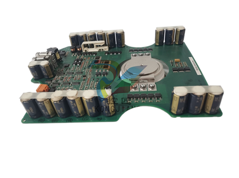
Stromversorgungseinheit 200-PSMG
Eingang DC 24 V (19,2–30 V einschl. max. 5%
Welligkeit) max. 1,3 A
Eingangssicherung 2 A träge, 250 V; IEC-127-3-Mikrosiche rung TR5
Eingangsstoßstrom Max. 4 A für 10 ms
Ausgleich von
Spannungsabfall Max. 0,3 ms
Ausgang DC 7–9 V; max. 2,2 A (1,8 A wenn
zusätzliche 200-PSSG verwendet wer den)
Taktfrequenz 4, 6, 8 und 12 MHz, abhängig von
Systemkonfigurationsgröße automa tisch eingestellt
Statusanzeigen Grüne LED-Anzeigen für Ausgangs spannung und Taktausgang;
Rote LED-Anzeigen für Initialisierungs fehleranzeige und Spannungsfehler
Potentialtrennung AC 500 V effektiv zwischen Eingang
und Ausgang
Anschlüsse Ein 200-BPP-Schraubklemmenblock
Erdung Direkt über Busmodul 200-BPN
Busmodulcode 7
Gewicht 0,170 kg ohne Verpackung
0,240 kg mit Verpackung
Abmessungen H 163 x B 45 x T 91 mm (ohne Anschlüs se und Schnappverschlüsse)
Bestellcode 200-PSMG
Stromversorgungseinheit 200-PSSG
Eingang DC 24 V (19,2–30 V einschl. max. 5%
Welligkeit) max. 1,3 A
Eingangssicherung 2 A träge 250 V; IEC-127-3-Mikrosiche rung TR5
Eingangsstoßstrom Max. 4 A für 10 ms
Ausgang DC 7–9 V; max. 1,8 A
Statusanzeigen Grüne LED für Ausgangsspannung
Rote LED für Spannungsfehler
Potentialtrennung AC 500 V effektiv zwischen Eingang
und Ausgang
Anschlüsse Ein 200-BPP-Schraubklemmenblock
Erdung Direkt über Busmodul 200-BPN
Busmodulcode 7
Gewicht 0,170 kg ohne Verpackung
0,240 kg mit Verpackung
Abmessungen H 163 x B 45 x T 91 mm (ohne Anschlüs se und Schnappverschlüsse)
Bestellcode 200-PSSG
RS232-Kommunikationsschnittstelle 200-CI232
Anzahl Kanäle 2
Kommunikations protokolle
COMLI (Client und Server), 3964R (Cli ent), MMS (SattLink) (Client und Server)
und benutzerdefiniert
Kommunikations schnittstelle
Asynchrone, serielle RS232C-Kommu nikation für TD, RD, RTS, CTS, DCD
und DTR
Statusanzeigen Grüne LED-Anzeigen für Stromversor gung OK und serielle Signale RD0, RD1,
TD0, TD1, RTS0 und RTS1
Potentialtrennung Keine
Übertragungs geschwindigkeiten
75, 110, 134, 150, 300, 600, 1200, 2400,
4800, 9600 (Standard), 19200 und
38400 Baud; max. Kabellänge: 15 m
Datenbits 7 oder 8 (Standard)
Parität Ungerade, gerade, keine
Stoppbits 1 (Standard) oder 2
Max. Last auf DTR 5 mA
Stromversorgung Über 200-PSMG/PSSG-Stromversor gungseinheiten
Interne Stromaufnahme
(von 200-PSMG/PSSG) Max. 0,2 A
Anschlüsse Zwei 200-BPP-Schraubklemmenblöcke;
zwei 9polige D-SUB-Buchsen an der
Vorderseite
Busmodulcode 8
Gewicht 0,200 kg ohne Verpackung
0,270 kg mit Verpackung
Abmessungen H 163 x B 45 x T 91 mm (ohne Anschlüs se und Schnappverschlüsse)
Bestellcode 200-CI232
RS485-Kommunikationsschnittstelle 200-CI485G
Anzahl Kanäle 2
Anzahl Netzknoten 32 pro Kanal
Kommunikations protokolle
COMLI (Client und Server), 3964R
(Client), MMS (SattLink) (Client und
Server) und benutzerdefiniert
Kommunikations schnittstelle
Asynchrone, serielle RS485-Kommuni kation für TD, RD und RTS
Statusanzeigen Grüne LED-Anzeigen für Stromversor gung OK und serielle Signale RD0, RD1,
TD0, TD1, RTS0 und RTS1
Potentialtrennung AC 500 V effektiv; die Kanäle sind ein zeln von der Hauptlogik und DC 24 V
getrennt.
Übertragungsgeschwin digkeiten
75, 110, 134, 150, 300, 600, 1200, 2400,
4800, 9600 (Standard), 19200 und
38400 Baud; max. Kabellänge: 1200 m
Datenbits 7 oder 8 (Standard)
Parität Ungerade, gerade, keine
Stoppbits 1 (Standard) oder 2
Stromversorgung Über 200-PSMG/PSSG-Stromversor gungseinh. und externes Stromversor gungsteil (DC 24 V)
Interne Stromaufnahme
(von 200-PSMG/PSSG) Max. 0,2 A
Externe Stromaufnahme Max. 0,1 A (von externer DC 24 V)
Anschlüsse Zwei 200-BPP-Schraubklemmenblöcke
Busmodulcode 8
Gewicht 0,220 kg ohne Verpackung
0,290 kg mit Verpackung
Abmessungen H 163 x B 45 x T 91 mm (ohne Anschlüs se und Schnappverschlüsse)
Bestellcode 200-CI485G
Purchase history
| User name | Member Level | Quantity | Specification | Purchase Date |
|---|
Total 0 Record
Related products

Customer Reviews
Satisfaction :
5 Stars
No evaluation information


- other
- ADLINK
- LTI Drives
- Other Brands
- AMAT
- Iba
- PEPPERL+FUCHS
- Aerotech
- WATLOW
- MAN
- ADVANCED
- Abaco
- YOKOGAWA
- KOLLMORGEN
- MEGGITT
- kong-sberg
- METSO
- Motorola
- NI
- OEMAX
- RELIANCE
- scanlab
- schneider
- uniop
- Vibro-Meter
- Honeywell
- Rolls-Royce
- MOOG
- GE
- B&R
- Woodward
- Yaskawa
- xYCOM
- Siemens
- Emerson
- HIMA
- Bently
- ZYGO
- FOXBORO
- OMACO
- PROSOFT
- ENTERASYS
- TRICONEX
- Parker
- Lenze
- KEBA
- Alstom
- CTI
- ABB
- A-B
172

-
 ADLINK DLAP-211 Series Fanless Edge AI Platform Specification Manual
 -
 ADLINK PCI/LPCI/LPCIe/cPCI-723X series 32 channel isolated digital I/O card
 -
 ADLINK cPCI-6965 series 6U CompactPCI single board computer
 -
 ADLINK NuDAQ 7200 series high-speed digital I/O board
 -
 Linghua ADLINK DLAP Deep Learning Acceleration Platform Product Manual
 -
 DEIF TCM-2 thyristor control module
 -
 Installation Manual for DEIF MVR-200 Series Medium Voltage Protection Device
 -
 DEIF MDR-2 multifunctional differential relay
 -
 DEIF AOM-1 Analog Output Module
 -
 DEIF AGI 400 series industrial/marine touch screen
 -
 Installation Manual for DEIF BRW-1 Marine Wing Bridge Instrument
 -
 DEIF AGC200 Quick Start Guide
 -
 DEIF AGC Multi line 2 Generator Set ControllerProduct basic information
 -
 ABB SPA-ZC 400 Ethernet Gateway Installation and Debugging Manual
 -
 ABB REM 543/545 motor generator protection device
 -
 DEIF PPU 300 controller
 -
 DEIF Delomatic 4 Offshore/Ocean Platform Dedicated Generator Power Management System DM-4
 -
 DEIF Delomatic Modular Generator Set Integrated System
 -
 DEIF AGC-4 Mk II Generator Set Controller
 -
 DEIF AGC-4 diesel generator set integrated controller
 -
 DEIF Multi line 2 Series PPU Unit Power Management (PPM) Operation Manual
 -
 DEIF Multi line 2 V2.4X Installation Manual
 -
 Beckwith M-6280 Digital Capacitor Bank Controller
 -
 Beckwith M-3311 Transformer Protection Relay
 -
 Beckwith M-3311A Transformer Integrated Protection Device
 -
 Beckwith M-3310 Transformer Integrated Protection Device Specification
 -
 Beckwith M-0359 Syncrocloser Check Plus Application Guide for Synchronous Calibration Relay
 -
 Beckwith M-0293A On Load Tap changer Controller Application Guide
 -
 DEIF GPU-3 Synchronous/Asynchronous Generator Integrated Microcomputer Protection Controller
 -
 Installation Instructions for DEIF PPM-3
 -
 Beckwith M-3520 distributed power grid connected comprehensive protection device
 -
 Beckwith M-3430 generator comprehensive protection device
 -
 Beckwith M-2293B adapter panel
 -
 Beckwith M-2001C digital on load voltage regulator controller
 -
 Beckwith M-2001B Digital On Load Voltage Regulating Controller
 -
 Beckwith M-0388/M-0389 synchronous verification relay
 -
 Beckwith M-0193B synchronous closing device
 -
 Beckwith M-0115A Transformer Parallel Balancing Module
 -
 Beckwith M-0067E on load tap changer controller
 -
 Beckwith M-4272 Digital Motor Bus Switching System
 -
 Beckwith M-3311A Transformer Integrated Protection Device
 -
 Beckwith M-3425A Generator Integrated Protection Device Manual
 -
 Basler BE1-27/BE1-59/BE1-27/59 undervoltage/overvoltage relay
 -
 Basler AVC63-12/AVC125-10 excitation voltage regulator
 -
 Basler L301kc Color Three Line Array Camera Operation Manual
 -
 Basler CBS 212A Current Enhanced Excitation System
 -
 Basler BE3-25 synchronous check relay
 -
 Operation Manual for Basler BE1-32R/BE1-32O/U Direction Power Relay
 -
 Basler Electric PRS-250 Veri Sync Synchronous Relay
 -
 Basler Pilot Series Area Array Industrial Camera piA2400-17gc
 -
 Basler BE1-11g comprehensive protection device for generator
 -
 Basler VR63-4C/UL Analog Excitation Voltage Regulator
 -
 Basler BE1-DFPR distribution feeder protection relay
 -
 Basler CBS310/CBS320 current strong excitation system
 -
 Basler UFOV250A/UFOV260A Low Frequency Overvoltage Module
 -
 Basler MVC104/MVC108/MVC232 manual voltage control device
 -
 Basler XR2002/XR2002F PMG excitation regulator
 -
 Basler DECS-400 Digital Excitation Control System
 -
 Basler DGC-2020 Digital Generator Set Controller
 -
 Basler MVC-300 Electronic Manual Excitation Controller
 -
 Basler MVC-104/MVC-108/MVC-232 manual excitation controller
 -
 Basler SSR32-12/SSR63-12/SSR125-12 Static Excitation Voltage Regulator
 -
 Basler SR4A/SR8A Analog Excitation Voltage Regulator
 -
 Basler BE2000E Digital Excitation Voltage Regulator
 -
 Basler DECS-2100 Digital Excitation System
 -
 Basler BE1-851 Overcurrent Protection Device Manual
 -
 Basler APR 63-5 Voltage Regulator
 -
 Basler BE1-FLEX Integrated Protection Control System
 -
 Basler BE1-700V digital voltage protection relay
 -
 Basler BE1-87B high impedance bus differential relay
 -
 Basler BE1-40Q demagnetization relay
 -
 Basler BE1-60 Voltage Balance Relay
 -
 Basler BE1-47N negative sequence voltage phase sequence relay
 -
 Basler BE1-81O/U digital frequency relay
 -
 Basler BE1-11f Feedline Integrated Protection Device Manual
 -
 Basler DECS-250 Digital Excitation Control System
 -
 Basler DECS-100 Digital Excitation Control System
 -
 Basler BE1-BPR Circuit Breaker Protection Relay
 -
 Basler BE1-50/51B-255 overcurrent relay
 -
 Basler BE1-25 synchronous check relay
 -
 Basler BE1-51 microcomputer time limited overcurrent relay
 -
 Basler DECS-300 Digital Excitation Control System
 -
 Mitsubishi MELSEC-F FX series programmable controllers
 -
 Hirschmann cSCALE Mobile Machinery Modular Controller
 -
 Hirschmann OZD Profi G12DU/G12DK/G12DE ATEX1 PROFIBUS Fiber Optic Repeater Manual
 -
 Hirschmann OCTOPUS OS20/OS24 Network Managed IP65/IP67 Industrial Switch Installation Manual
 -
 Hirschmann RS20/RS22/RS30/RS32/RS40 Series Industrial Rail Switch Installation Manual
 -
 Hirschmann EAGLE One Industrial Ethernet Firewall Installation Manual
 -
 Hirschmann MACH102 Series Industrial Switch Installation Manual
 -
 Hirschmann MS20/MS30 Modular Industrial Switch Installation Manual
 -
 Hirschmann BRS20/22/30/32/40/42/50/52 Series BOBCAT Industrial Rail Switch Installation Manual
 -
 Hirschmann RSB20 Basic Series Industrial Rail Switch Installation Manual
 -
 Hirschmann RS20 Basic Series Industrial Ethernet DIN-Rail Switches
 -
 BECKHOFF EP20xx/EP28xx IP67 EtherCAT Box Digital Output Module
 -
 BECKHOFF EL5102 Incremental Encoder Terminal Manual
 -
 BECKHOFF CU8803-000x CP Link4 Launch Box Operation Manual
 -
 Beckhoff CU20xx/CU22xx Industrial Unmanned Switch Manual
 -
 BECKHOFF AMP8000 Distributed Servo System Operation Manual
 -
 BECKHOFF EL2911/EL2911-2200 TwinSAFE Safety Potential Supply Terminal Manual
 -
 BECKHOFF EL600x/EL602x series EtherCAT serial port terminal module
 -
 BECKHOFF CP6700-0001-0050/0060 Integrated Machine Manual
 -
 BECKHOFF CP70xx Series Control Panel Installation and Operation Manual
 -
 BECKHOFF CP29xx Cabinet Mounted Industrial Touch Panel Official Operation Manual
 -
 Beckhoff C6650-0060 Control Cabinet Industrial PC
 -
 Beckhoff BK series K-bus to EtherCAT coupler
 -
 Beckhoff CX20x0 Series Embedded Industrial Control Computer Manual
 -
 Beckhoff CP77xx Series Industrial Panel PC Installation and Operation Manual
 -
 Beckhoff EL41xx Series 16 Bit Analog Output Terminal Manual
 -
 Beckhoff C63xx-0020 series control cabinet industrial PC
 -
 Beckhoff C6920-0060 Control Cabinet Industrial PC
 -
 Beckhoff CU8800-0010 USB transmitter extender (TX)
 -
 Beckhoff AX2000 series digital servo amplifier
 -
 Beckhoff AX8000 Modular Multi Axis Servo System
 -
 Beckhoff CP27xx Embedded Panel PC User Manual
 -
 Beckhoff CP69xx Industrial Embedded Control Panel
 -
 Beckhoff CP60xx Embedded Industrial Control Panel
 -
 Beckhoff CP72xx series panel PC official installation, operation, configuration, maintenance, and troubleshooting
 -
 Installation and Operation of Beckhoff CP78xx Series Control Panel
 -
 Beckhoff CP39xx series industrial touch control panel
 -
 Beckhoff CX8110 Embedded Industrial PC
 -
 Beckhoff CX50x0 series DIN rail embedded industrial PC
 -
 Beckhoff CP62xx series embedded panel PC
 -
 BECKHOFF C6030 Compact Industrial PC
 -
 UniOP ePAD32B/ePAD33B/ePAD33BT Industrial HMI
 -
 UniOP ePAD05&ePAD06 Industrial HMI
 -
 UniOP ePAD03/ePAD04 entry-level HMI
 -
 UniOP CP01R-04 Compact Industrial HMI
 -
UniOP BKDR-16 Industrial Human Machine Interface

K-JIANG

Add: Jimei North Road, Jimei District, Xiamen, Fujian, China
Tell:+86-15305925923