
K-WANG
+086-15305925923
Service expert in industrial control field!


Product
Article
NameDescriptionContent
Adequate Inventory, Timely Service
pursuit of excellence


Ship control system
Equipment control system
Power monitoring system
Brand
Description
ABB MEASUREMENT & ANALYTICS
NGC Series and PGC1000
Quick Start Guide
ABB PGC1000 MEASUREMENT&ANALYTICS NGC
Comm 1 and Comm 2 Pinouts/Terminations
PINRS-232 RS-485 RS-422
COMM 1 (J8) COMM 1 (J8) COMM 1 (J8)
1 Power Out Power Out Power Out
2 Ground Ground Ground
3 Switched Power Out Switched Power Out Switched Power Out
4 Operate Operate Operate
5 Not Used RRTS RTS
6 Request To Send Bus + Transmit Bus +
7 Transmit Data Bus - Transmit Bus -
8 Receive Data No Connection Receive Bus +
9 Clear To Send (CTS) No Connection Receive Bus -
COMM 2 (J10) COMM 2 (J10) COMM 2 (J10)
1 Power Out Power Out Power Out
2 Ground Ground Ground
3 Switched Power Out Switched Power Out Switched Power Out
4 Operate Operate Operate
5 Not Used RRTS RTS
6 Request To Send Bus + Transmit Bus +
7 Transmit Data Bus - Transmit Bus -
8 Receive Data No Connection Receive Bus +
9 Clear To Send (CTS) No Connection Receive Bus -
TERMINATIONS Comm 1 (J9) Comm 2 (J11)
First or intermediate unit
(RS-485) Pins 2–3 Pins 2–3
Last or only unit
(RS-485) Pins 1–2 Pins 1–2
RS-232 Pins 2–3 Pins 2–3
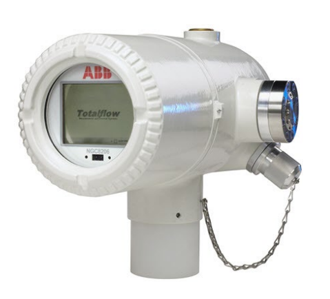
NGC and PGC1000 Quick Start Guide
Connect sample streams
IMPORTANT NOTE: Do not use any type of
plastic, Teflon™ or Teflon-lined braided steel
tubing. Use only good quality, clean, stainless steel
chromatographic-grade transport tubing for carrier,
calibration gas and sample lines. Use of poor-quality
stainless-steel tubing will generate unsatisfactory
results. H2S applications require Sulfinert® tubing.
IMPORTANT NOTE: Use only ultra-high purity grade
carrier gas. Purge all lines prior to connecting to the
device.
IMPORTANT NOTE: The transport tubing run for the
sample conditioning modules can be up to 50 feet.
Lengths longer than 50 feet must adhere to the rules
of calculated lag time.
If a sample conditioning module is not being used, the
sample transport tubing should be 1/16-inch tubing
and no longer than ten feet.
To calculate lag time:
Tube outside diameter Tube wall thickness Volume per foot
1/8 inch 0.02 inch 1 cc
¼ inch 0.035 inch 5 cc
3/8 inch 0.035 inch 15 cc
½ inch 0.035 inch 25 cc
Common settings
Set the carrier regulator to 90 PSIG.
Set calibration blend/sample stream pressures to
between 15 ±2 PSIG.
Ensure valves are open.
Power supply information
For a 12-volt power supply, 8 amps are required. Set
the power supply to 14.5 volts. For a 24-volt power
supply, 4 amps are required. Set the power supply to
25-26.5 volts.
Recommended wire size is 12 AWG.
Startup using USB
After the unit has been powered up for a minimum of 2
hours for temperature stabilization, continue with the
following steps:
Verify that carrier, sample, and cal pressures are
set correctly.
Connect with a USB cable (to connect using
Ethernet, see the NGC8200/PGC1000 Gas
Chromatograph User Manual).
1. Start PCCU32.
2. Click the Setup icon on top tool bar.
3. On the System Setup tab, select Serial port.
4. Select the port from the PCCU Com. Port drop down list.
5. Click Close to exit setup.
6. Click the Entry icon , then View > Expert.
The Start-up Wizard will initialize to assist with analyzer
setup. If you choose not to use the Wizard or if it fails
to start, continue with the next step.
7. Select Show Tree View (on the left).
8. Select Totalflow from the top of the tree.
9. In the Station Setup Tab, under the Value
Column, select Totalflow.
10. Change the default ID.
11. Click Send.
12. Select Analyzer Operation in the tree view (on
the left) to open the Main Screen.
13. Select the Stream Sequence tab and enable the
streams to be used.
14. Click Send.
15. Select Diagnostics (on the right) to verify that
diagnostic tests were successful.
Unused streams will fail stream tests since no pressure
is applied.
16. Select Calibration (on the right).
a. Enter calibration blend information from certificate.
b. Verify that the blend total equals 100%.
17. Click Send.
18. Close the window.
19. Select Peak Find (on the right). Verify that
Manual is selected. (Do not use Auto).
20. Select Run Single Cycle and review the
chromatogram:
Verify that all peaks are gated and labeled.
Verify that the reference peaks have appropriate
retention times and there are no alarms.
21. Click CAL (on the left side of the main screen).
IMPORTANT NOTE: Calibration will take
approximately 30 minutes.
After calibration is accepted:
1. Select stream 4 to run calibration gas again.
2. After the stream starts, select HOLD so it runs
only one time. This will update stream data.
3. Verify stream 4 results are acceptable.
4. Select Run (on the left) to put the unit in service
analyzing process stream(s).
To save the configuration:
1. Click the Save & Restore icon on top toolbar.
2. In the Save and Restore window, click Restore
Station Files.
3. Verify the default name and path for the files.
Click OK. This will restore the files to the tfCold
drive.
Purchase history
| User name | Member Level | Quantity | Specification | Purchase Date |
|---|
Total 0 Record
Related products
Customer Reviews
Satisfaction :
5 Stars
No evaluation information


- other
- ADLINK
- LTI Drives
- Other Brands
- AMAT
- Iba
- PEPPERL+FUCHS
- Aerotech
- WATLOW
- MAN
- ADVANCED
- Abaco
- YOKOGAWA
- KOLLMORGEN
- MEGGITT
- kong-sberg
- METSO
- Motorola
- NI
- OEMAX
- RELIANCE
- scanlab
- schneider
- uniop
- Vibro-Meter
- Honeywell
- Rolls-Royce
- MOOG
- GE
- B&R
- Woodward
- Yaskawa
- xYCOM
- Siemens
- Emerson
- HIMA
- Bently
- ZYGO
- FOXBORO
- OMACO
- PROSOFT
- ENTERASYS
- TRICONEX
- Parker
- Lenze
- KEBA
- Alstom
- CTI
- ABB
- A-B
172

-
 ADLINK NuPRO-E320 PICMG1.3 Full length Industrial Motherboard
 -
 ADLINK NuPRO-800 Series Full length Industrial SBC User Manual
 -
 ADLINK NuPRO-598 Industrial Single Board Computer
 -
 ADLINK MXC-6300 Fanless Embedded Industrial Control Computer
 -
 ADLINK Express-BASE7 User Manual
 -
 ADLINK DLAP-211 Series Fanless Edge AI Platform Specification Manual
 -
 ADLINK PCI/LPCI/LPCIe/cPCI-723X series 32 channel isolated digital I/O card
 -
 ADLINK cPCI-6965 series 6U CompactPCI single board computer
 -
 ADLINK NuDAQ 7200 series high-speed digital I/O board
 -
 Linghua ADLINK DLAP Deep Learning Acceleration Platform Product Manual
 -
 DEIF TCM-2 thyristor control module
 -
 Installation Manual for DEIF MVR-200 Series Medium Voltage Protection Device
 -
 DEIF MDR-2 multifunctional differential relay
 -
 DEIF AOM-1 Analog Output Module
 -
 DEIF AGI 400 series industrial/marine touch screen
 -
 Installation Manual for DEIF BRW-1 Marine Wing Bridge Instrument
 -
 DEIF AGC200 Quick Start Guide
 -
 DEIF AGC Multi line 2 Generator Set ControllerProduct basic information
 -
 ABB SPA-ZC 400 Ethernet Gateway Installation and Debugging Manual
 -
 ABB REM 543/545 motor generator protection device
 -
 DEIF PPU 300 controller
 -
 DEIF Delomatic 4 Offshore/Ocean Platform Dedicated Generator Power Management System DM-4
 -
 DEIF Delomatic Modular Generator Set Integrated System
 -
 DEIF AGC-4 Mk II Generator Set Controller
 -
 DEIF AGC-4 diesel generator set integrated controller
 -
 DEIF Multi line 2 Series PPU Unit Power Management (PPM) Operation Manual
 -
 DEIF Multi line 2 V2.4X Installation Manual
 -
 Beckwith M-6280 Digital Capacitor Bank Controller
 -
 Beckwith M-3311 Transformer Protection Relay
 -
 Beckwith M-3311A Transformer Integrated Protection Device
 -
 Beckwith M-3310 Transformer Integrated Protection Device Specification
 -
 Beckwith M-0359 Syncrocloser Check Plus Application Guide for Synchronous Calibration Relay
 -
 Beckwith M-0293A On Load Tap changer Controller Application Guide
 -
 DEIF GPU-3 Synchronous/Asynchronous Generator Integrated Microcomputer Protection Controller
 -
 Installation Instructions for DEIF PPM-3
 -
 Beckwith M-3520 distributed power grid connected comprehensive protection device
 -
 Beckwith M-3430 generator comprehensive protection device
 -
 Beckwith M-2293B adapter panel
 -
 Beckwith M-2001C digital on load voltage regulator controller
 -
 Beckwith M-2001B Digital On Load Voltage Regulating Controller
 -
 Beckwith M-0388/M-0389 synchronous verification relay
 -
 Beckwith M-0193B synchronous closing device
 -
 Beckwith M-0115A Transformer Parallel Balancing Module
 -
 Beckwith M-0067E on load tap changer controller
 -
 Beckwith M-4272 Digital Motor Bus Switching System
 -
 Beckwith M-3311A Transformer Integrated Protection Device
 -
 Beckwith M-3425A Generator Integrated Protection Device Manual
 -
 Basler BE1-27/BE1-59/BE1-27/59 undervoltage/overvoltage relay
 -
 Basler AVC63-12/AVC125-10 excitation voltage regulator
 -
 Basler L301kc Color Three Line Array Camera Operation Manual
 -
 Basler CBS 212A Current Enhanced Excitation System
 -
 Basler BE3-25 synchronous check relay
 -
 Operation Manual for Basler BE1-32R/BE1-32O/U Direction Power Relay
 -
 Basler Electric PRS-250 Veri Sync Synchronous Relay
 -
 Basler Pilot Series Area Array Industrial Camera piA2400-17gc
 -
 Basler BE1-11g comprehensive protection device for generator
 -
 Basler VR63-4C/UL Analog Excitation Voltage Regulator
 -
 Basler BE1-DFPR distribution feeder protection relay
 -
 Basler CBS310/CBS320 current strong excitation system
 -
 Basler UFOV250A/UFOV260A Low Frequency Overvoltage Module
 -
 Basler MVC104/MVC108/MVC232 manual voltage control device
 -
 Basler XR2002/XR2002F PMG excitation regulator
 -
 Basler DECS-400 Digital Excitation Control System
 -
 Basler DGC-2020 Digital Generator Set Controller
 -
 Basler MVC-300 Electronic Manual Excitation Controller
 -
 Basler MVC-104/MVC-108/MVC-232 manual excitation controller
 -
 Basler SSR32-12/SSR63-12/SSR125-12 Static Excitation Voltage Regulator
 -
 Basler SR4A/SR8A Analog Excitation Voltage Regulator
 -
 Basler BE2000E Digital Excitation Voltage Regulator
 -
 Basler DECS-2100 Digital Excitation System
 -
 Basler BE1-851 Overcurrent Protection Device Manual
 -
 Basler APR 63-5 Voltage Regulator
 -
 Basler BE1-FLEX Integrated Protection Control System
 -
 Basler BE1-700V digital voltage protection relay
 -
 Basler BE1-87B high impedance bus differential relay
 -
 Basler BE1-40Q demagnetization relay
 -
 Basler BE1-60 Voltage Balance Relay
 -
 Basler BE1-47N negative sequence voltage phase sequence relay
 -
 Basler BE1-81O/U digital frequency relay
 -
 Basler BE1-11f Feedline Integrated Protection Device Manual
 -
 Basler DECS-250 Digital Excitation Control System
 -
 Basler DECS-100 Digital Excitation Control System
 -
 Basler BE1-BPR Circuit Breaker Protection Relay
 -
 Basler BE1-50/51B-255 overcurrent relay
 -
 Basler BE1-25 synchronous check relay
 -
 Basler BE1-51 microcomputer time limited overcurrent relay
 -
 Basler DECS-300 Digital Excitation Control System
 -
 Mitsubishi MELSEC-F FX series programmable controllers
 -
 Hirschmann cSCALE Mobile Machinery Modular Controller
 -
 Hirschmann OZD Profi G12DU/G12DK/G12DE ATEX1 PROFIBUS Fiber Optic Repeater Manual
 -
 Hirschmann OCTOPUS OS20/OS24 Network Managed IP65/IP67 Industrial Switch Installation Manual
 -
 Hirschmann RS20/RS22/RS30/RS32/RS40 Series Industrial Rail Switch Installation Manual
 -
 Hirschmann EAGLE One Industrial Ethernet Firewall Installation Manual
 -
 Hirschmann MACH102 Series Industrial Switch Installation Manual
 -
 Hirschmann MS20/MS30 Modular Industrial Switch Installation Manual
 -
 Hirschmann BRS20/22/30/32/40/42/50/52 Series BOBCAT Industrial Rail Switch Installation Manual
 -
 Hirschmann RSB20 Basic Series Industrial Rail Switch Installation Manual
 -
 Hirschmann RS20 Basic Series Industrial Ethernet DIN-Rail Switches
 -
 BECKHOFF EP20xx/EP28xx IP67 EtherCAT Box Digital Output Module
 -
 BECKHOFF EL5102 Incremental Encoder Terminal Manual
 -
 BECKHOFF CU8803-000x CP Link4 Launch Box Operation Manual
 -
 Beckhoff CU20xx/CU22xx Industrial Unmanned Switch Manual
 -
 BECKHOFF AMP8000 Distributed Servo System Operation Manual
 -
 BECKHOFF EL2911/EL2911-2200 TwinSAFE Safety Potential Supply Terminal Manual
 -
 BECKHOFF EL600x/EL602x series EtherCAT serial port terminal module
 -
 BECKHOFF CP6700-0001-0050/0060 Integrated Machine Manual
 -
 BECKHOFF CP70xx Series Control Panel Installation and Operation Manual
 -
 BECKHOFF CP29xx Cabinet Mounted Industrial Touch Panel Official Operation Manual
 -
 Beckhoff C6650-0060 Control Cabinet Industrial PC
 -
 Beckhoff BK series K-bus to EtherCAT coupler
 -
 Beckhoff CX20x0 Series Embedded Industrial Control Computer Manual
 -
 Beckhoff CP77xx Series Industrial Panel PC Installation and Operation Manual
 -
 Beckhoff EL41xx Series 16 Bit Analog Output Terminal Manual
 -
 Beckhoff C63xx-0020 series control cabinet industrial PC
 -
 Beckhoff C6920-0060 Control Cabinet Industrial PC
 -
 Beckhoff CU8800-0010 USB transmitter extender (TX)
 -
 Beckhoff AX2000 series digital servo amplifier
 -
 Beckhoff AX8000 Modular Multi Axis Servo System
 -
 Beckhoff CP27xx Embedded Panel PC User Manual
 -
 Beckhoff CP69xx Industrial Embedded Control Panel
 -
 Beckhoff CP60xx Embedded Industrial Control Panel
 -
 Beckhoff CP72xx series panel PC official installation, operation, configuration, maintenance, and troubleshooting
 -
 Installation and Operation of Beckhoff CP78xx Series Control Panel
 -
 Beckhoff CP39xx series industrial touch control panel
 -
 Beckhoff CX8110 Embedded Industrial PC
 -
 Beckhoff CX50x0 series DIN rail embedded industrial PC
 -
 Beckhoff CP62xx series embedded panel PC
 -
 BECKHOFF C6030 Compact Industrial PC

K-JIANG

Add: Jimei North Road, Jimei District, Xiamen, Fujian, China
Tell:+86-15305925923