

K-WANG


PROFIBUS ® PA fieldbus is a fully digital serial bidirectional communication system used as a local area network (LAN) in factory/workshop instruments
And in the control device.
PROFIBUS ® Fieldbus is a CENELEC standard EN50170-2, which includes Profibus FMS, DP, and PA, compliant with DIN standard 19245 parts 1 and 2, and PA adapted to standard 19245 part 3, just like DPE.
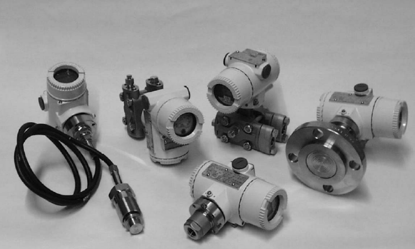
ABB 2600T pressure transmitter
3.2- Fault Protection
This electronic device also uses a special circuit for fault current protection. When a major fault occurs and the current consumption exceeds 20mA, this circuit will operate the equipment
Disconnect from the bus to protect the functional integrity of other connected devices, otherwise these devices may be shut down due to a lack of power.
3.3- Hardware Settings
There are four DIP switches (see Figure 1) on the electronic unit behind the local display (if installed), which have the following functions:
Write lock:
-Enable write lock state when SW1 is in the ON position. whatever
Changes to configuration settings have been rejected.
SW2 not used: (to be used in the future).
cold boot:
-When SW3 is in the ON position, enable cold start. Cold start power
The purpose of being able to use default values to initialize all requirements is to ensure accuracy
Parameters with significant values. When performing this operation, turn on the device power
Before starting, set the cold start switch 3 to the ON position. AIFB
Many variables of TB are correctly set to only be connected to
The numerical values related to the converter type.
SW4 not used: (to be used in the future).
3.4- On site display
The 2600T264 PROFIBUS PA pressure transmitter comes with an optional LCD local display, as shown in Figure 2.
This display is in a dot matrix format, with one 5-digit row to display numerical values and one 7-digit row
Character, text, and number lines are used to display strings and unit codes, as well as one
50 segment bar chart. This can be installed on the transmitter and can display the converter
The variables generated by the block and the engineering values or their percentages output by the functional block
Compare or display certain diagnostic strings when a fault or warning is detected.
In addition, it can also provide feedback on on-site operations performed on external keys.
The programmability of the transmitter through LCD display is usually available for testing
At the beginning of operation, the FF network is not functioning properly or the host configuration is not working properly
The tool is not yet usable. When the host is ready, it can be accessed through
The PB_LOCAL_OP-ENA parameter cancels in place programmability.
LCD ordinary display can work in two different modes:
Continuous display (simple indication)
On site operation monitoring
3.4.1- Continuous Display
When the LCD display is used for continuous display (default state), the selected variable in PB_LCD_VAL_SEL is displayed. Refer to Section 8 of the Physical Block Table.
The behavior of LCD depends on the quality status of the variables to be displayed.
-When the quality is Good, the value is displayed continuously and updated once per second.
-When the quality is UNCERTAIN, the monitor will display variable values and the original uncertainty in alternating mode (once per second)
Due to the relevant diagnostic string.
-When the quality is bad (BAD), the value will no longer be displayed and the display will flash (once per second) to show the diagnostic string related to the cause of the fault.
When displaying variables, numerical values with unit codes and bar charts appear on the LCD.
The bar chart always displays the percentage of AIFB1_OUT, indicating the implementation of links with process variables.
The operating modes of AIFB are described in Section 9- Operating Modes and produce the following results on the display: Î
When AIFB is in Out of Service mode, AIFB-OUT_Status is BAD-OUT
Of Service (not working) and flashing the string Î on the monitor
When AIFB is in Manual Mode, AIFB-OUT_Status is
UNCERTAIN Manual Mode, displaying this string and AIFB-OUT hand
When AIFB is in AUTO, the process flow is normal and the display shows the selected variable.
More indication information may appear depending on the selected variable that needs to be displayed. When displaying OUT_SB1 or OUT_SB2, if the value exceeds the limit
Limit (HI-HI, LO_LO,HI,LO), It will display a special character along with the numerical value.
3.4.2- On site operation monitoring
After holding down two external keys for more than 2 seconds (ENTER operation), the display mode will automatically switch from continuous display to on-site operation of the monitor. When the first string 'REVIEW' appears on the monitor as the first of the four main menus, this state is confirmed, as shown in Figure 3 below.
In the on-site operation monitor mode, the functions of external keys Z and S are changed. When these keys are pressed:
-Only Z=NEXT (next)
-Only S=Previous
-Z and S together for more than 2 seconds=ENTER
-Z and S together for less than 2 seconds=ESCAPE (exit)
Check Quick Reference
Menu submenu item description
TAG displays 32 characters of 'PB_TAG_deSC' on 3 screens
Address displays' Device Node Address'
SW REV Display Specific Software Revision Version - TB_SW-PRIV_REV
HD REV Display Specific Hardware Revision Version - TB-HW-PRIV_REV
The first line of PV TYPE displays a string for TB-PRIMRYVNet TYPE:
Like DIFF, PRESS,FLOW,LEVEL,VOLUME;
The second line displays a string for TB_LIN_Type:
Such as LINEAR, SQR, TABLE
SENSOR LSL displays the lower limit of the sensor+unit TB_SNSOR_LO_LIM+
TB_SENSOR_UNIT
USL displays the upper limit of the sensor+unit - TB_SENSOR_SHI_LIM+
TB_SENSOR_UNIT
MIN_SPAN displays the minimum range+unit - TB-CAL_MIN_SPAN
+TB_SENSOR_UNIT
CAL-POINT-HI displays university punctuality+unit - TB_CAL-POINT-HI+
TB_SENSOR_UNIT
CAL-POINT_LO displays low calibration point+unit TB_CAL-POINT_LO+
TB_SENSOR_UNIT
F_BLOCK is only available for connections to TB-PRIMRYVNet (channel=1)
UNIT displays AIFB-OUT_SCALE.Unit
SCALE_L displays the AIFB'OUT_SCALE_High Range
SCALE-H displays AIFB-OUT_SCALE_Low Range
Filter displays AIFB-PV_TIME+"Seconds" IMIT
H_H_LIM displays AIFB-HII_LIM
H_LIM displays AIFB-HILIM
L_L_LIM displays AIFB_LOLO_LIM
L_LIM displays AIFB_LOLIM
DspMode displays PB_LCDVNet SEL:
OUT_FB1,OUT FB1%,OUT_FB2,OUT_FB2%,TrimVal,
OUT_TB (see display configuration)
| User name | Member Level | Quantity | Specification | Purchase Date |
|---|


- LTI Drives
- other
- ADLINK
- Beckhoff
- Shinkawa
- Other Brands
- AMAT
- Iba
- PEPPERL+FUCHS
- Aerotech
- WATLOW
- MAN
- ADVANCED
- Abaco
- YOKOGAWA
- KOLLMORGEN
- MEGGITT
- kong-sberg
- METSO
- Motorola
- NI
- OEMAX
- RELIANCE
- scanlab
- schneider
- uniop
- Vibro-Meter
- Honeywell
- Rolls-Royce
- MOOG
- GE
- B&R
- Woodward
- Yaskawa
- xYCOM
- Siemens
- Emerson
- HIMA
- Bently
- ZYGO
- FOXBORO
- OMACO
- PROSOFT
- ENTERASYS
- TRICONEX
- Parker
- Lenze
- KEBA
- Alstom
- CTI
- ABB
- A-B

-
 Foxboro E69F-BI2 on-site installation type electric pneumatic converter (I/P)
 -
 Foxboro DCS Compact200 series RH916RB (16 slot horizontal bottom plate)
 -
 Operation Instructions for Reliance Electric PSC7000 Control Card
 -
 Eaton MTL F809F Plus DTM Operating Instructions
 -
 Motorola ACE3600 series remote terminal unit RTU
 -
 MOOG D136-003-001 Rugged Motion Controller
 -
 Micro Innovation GF1 series industrial touch screen (Micro Panel)
 -
 Neles ™ NDX ™ Compact intelligent valve controller (positioner)
 -
 Jamesbury Valv‑Powr ™ Installation, maintenance, and operation of VPVL mod D actuator
 -
 Jamesbury Valv‑Powr ™ VPVL series D-type compact gear rack pneumatic actuator
 -
 GMW IPP 144-40G Embedded Thermal Printer
 -
 Meggitt C327845 flow cut-off valve
 -
 Meggitt C422425/C422685/C422695/C422705 solenoid valve
 -
 Selection of LTi Drives ServoOne Full Series Servo Drive Systems
 -
 Jenaer Antriebstechnik ECOVARIO ® Installation and Operation Instructions for 114/214/414 Servo Drivers
 -
 Honeywell TDC3000X APM Advanced Process Manager
 -
 Honeywell Notifier NFS2-3030 Intelligent Addressing Fire Alarm Controller
 -
 Honeywell EP-DOCX-SCA-SMSC-100 Universal Signal Conditioning Wiring Solution for Safety Systems (UMS)
 -
 Installation Instructions for Honeywell XL1404 Fire Alarm Controller
 -
 Honeywell Enhanced Micro TDC 3000 (MT11-520) DCS Control System
 -
 HIMA X-DI 64 01 Digital Input Module
 -
 Hirschmann MICE MS20/MS30 Industrial Switch Installation Instructions
 -
 Exor UniOP ePAD05/ePAD06 Compact HMI Industrial Human Machine Panel
 -
 Exor Effectiveness View eV058- TST/eV058- TNT Industrial Touch Screen HMI Human Machine Panel
 -
 Esd VME-PMC CADDY/2 Intelligent VME-PMC Carrier Board
 -
 Installation Instructions for Elmo Gold Tuba (G-TUB) Servo Drive
 -
 Eaton COM-MPB1-TP/COM-MPB2-TP communication module
 -
 Delta Tau Turbo PMAC2 PCI Ultralite Programmable Multi Axis Motion Controller
 -
 DATA PATTERNS DP-VME-5114 module
 -
 CMZ SVM Series Independent Two Phase Synchronous Servo Driver SVM1608 Product Specification
 -
 SUMITOMO T2100Z steel turning
 -
 SUMITOMO PSZ Turn Modular Quick Change Tool System
 -
 SUMITOMO EGU positive front corner chip breaker groove
 -
 SUMITOMO GND series slotting and cutting tools
 -
 SUMITOMO AC8000P series (AC8115P/AC8020P/AC8025P/AC8035P) steel turning
 -
 SUMITOMO AC6000M series (AC6020M/AC6030M/AC6135M/AC6145M) stainless steel turning
 -
 SUMITOMO ELECTRIC AC5000S series (AC5005S/AC5015S/AC5025S) heat-resistant alloy turning
 -
 SUMITOMO ELECTRIC AC4000K series (AC4010K/AC4015K/AC4125K) cast iron turning
 -
 SUMITOMO ELECTRIC AC1135U small lathe for turning small parts
 -
 SUMITOMO ELECTRIC AC1030U Material Blade
 -
 CCS 6900G/6900P Non Explosion proof Pressure Switch Installation and Maintenance Manual
 -
 BENDER WR70 × 175S (P)~WR200 × 500S (P) rectangular measuring current transformer
 -
 BENDER RCMA475LY B-type residual current monitor
 -
 BENDER IRDH575 A‑ISOMETER ® Insulation monitoring device
 -
 BENDER IRDH265 / IRDH365(ISOMETER ®) Insulation monitoring device
 -
 BENDER RCMA475LY AC/DC sensitive residual current monitor
 -
 Beckwith Electric M-3425A Generator Integrated Protection Relay
 -
 Automated Logic MEx816u I/O Expansion Module
 -
 ASEM HT2150 Fanless Industrial Panel X86
 -
 Advantest U3771/U3772 portable microwave millimeter wave spectrum analyzer
 -
 Advantest R6144 Programmable DC Voltage/Current Source (Calibration Source)
 -
 Aerotech UNIDEX 100/U100i single axis motion controller
 -
 Aerotech Ndrive MP Ultra Compact PWM Digital Servo Driver
 -
 Aerotech Ndrive HPe 10/20/30 High Performance PWM Digital Servo Drive
 -
 Aerotech Ndrive Linear (HLe/ML) Linear Servo Drive
 -
 Aerotech Ndrive CP Compact PWM Digital Servo Driver
 -
 Aerotech Ndrive Linear (HLe/CL/ML) linear servo drive
 -
 Aerotech Ndrive HL (EDU176 Rev1.08b) Digital Servo Drive
 -
 Aerotech Ndrive HP10/20/30 PWM Digital Servo Drive
 -
 Aerotech Ndrive series digital servo drives
 -
 SIGMATEK TAE 1941 Touch Display Unit
 -
 SIGMATEK TAE 151 Touch Display Unit
 -
 SIGMATEK AKM series servo motor
 -
 SIGMATEK S-DIAS Control System
 -
 SIGMATEK Human Machine Interface (HMI)
 -
 SIGMATEK DIAS Drive 310-23 servo amplifier
 -
 SIGMATEK CCP 521 C-DIAS processor module
 -
 MEGMEET L6 series electric drive
 -
 Sysmex XN-1000/XN-2000 Hematology Analyzer
 -
 Sysmex XN-L series (XN-530/XN-430/XN-330) fully automatic blood cell analyzer
 -
 Sysmex XN-9000 Series Fully Automated Blood Analysis Pipeline
 -
 LTI‑Motion ServoOne Field Bus Systems PROFIBUS and PROFINET
 -
 Micro Innovation MICRO PANEL GF1 Color Touch Human Computer Interface
 -
 Micro Innovation WINbloc Distributed Remote I/O System
 -
 Micro Innovation MICRO PANEL GS-2 Industrial Touch Visualization Operation Panel (HMI)
 -
 LTi LST/LSH series synchronous servo motor
 -
 LTi CDE/CDB3000 positioning controller
 -
 ENOTEC SILOTEC ® Installation and Operation Instructions for 8000 Silo Monitoring O ₂/CO ₑ Analyzer System
 -
 ENOTEC ENSITU ® 7000 Compact Oxygen Transmitter Probe
 -
 ENOTEC COMTEC ® Installation and Operation Instructions for 6000 ATEX GasEx Explosion proof O ₂/COE Analyzer System
 -
 ENOTEC Integrated Products
 -
 ENOTEC OXITEC ® 500E Extraction Oxygen Analyzer
 -
 KUKA KR CS Box-2 Compact Controller for Four Axis SCARA Robot
 -
 KUKA KR C5 slim-2 Robot Controller
 -
 KUKA KR C5 micro With KUKA System Software (KSS/VSS) Assembly Instructions
 -
 KUKA KR C5 micro controller
 -
 KUKA KR C5 Controller Assembly Instructions
 -
 KUKA KR C5 compactcab and KR C5 small-size cab cabinets
 -
 KUKA KR C4 smallsize-2 small robot control cabinet
 -
 KUKA KR C4 Midsize/KR C4 Midsize CK Assembly Manual
 -
 ENOTEC ® Installation and Operation Instructions for 5000/5000+Oxygen Analyzer System
 -
 KUKA KR C4 extended; KR C4 extended CK Assembly Instructions Assembly Manual
 -
 Assembly/Installation Manual for KUKA KR C4 Compact Control Cabinet
 -
 KUKA Sunrise Cabinet Med Medical Collaborative Robot Special Control Cabinet
 -
 KUKA Sunrise Cabinet Next Generation Small Control Cabinet
 -
 KUKA KR C4 Smallsize-2 family's smallest control cabinet
 -
 KUKA KR C4 midsize; KR C4 midsize CK medium-sized control cabinet
 -
 KUKA KR C4 extended is a high-power multi axis control cabinet
 -
 General installation and operation instructions for KUKA KR C4 and KR C4 CK controllers
 -
 KUKA KR C4 compact controller operation instructions
 -
 Installation and Operation Instructions for KUKA Robot Arm
 -
 KUKA TITAN-2 Ultra Ground Overloading Six Axis Robot
 -
 Assembly instructions for KUKA KR SCARA-2 CS series robotic arm body
 -
 KUKA MA KR SCARA X Installation Guide
 -
 KUKA KR FORTEC-2 Ultra Heavy duty Ground Six Axis Robot Mechanical Assembly Manual
 -
 KUKA KR FORTEC-2 new generation heavy-duty ground six axis robot
 -
 KUKA Robots KR 1000 titan; KR 1000 L750 titan With F Variants Assembly Instructions
 -
 KUKA KR 600 FORTEC heavy-duty six axis ground mounted industrial robot
 -
 KUKA KR 500 MT FORTEC Heavy duty Six Axis Industrial Robot
 -
 KUKA KR 360 FORTEC Heavy duty Six Axis Industrial Robot
 -
 KUKA Sunrise Cabinet Med Medical Edition Robot Controller User Manual
 -
 KUKA Robots KR SCARA HO Assembly Instructions
 -
 KUKA Robots KR QUANTEC-2 PA Assembly Instructions
 -
 KUKA Robots KR QUANTEC-2 K and KR QUANTEC-2 P With K-F and P-C Variants Assembly Instructions
 -
 KUKA Robots KR QUANTEC-2 HO Assembly Instructions
 -
 KUKA Robots KR QUANTEC-2 HC Assembly Instructions
 -
 KUKA KR QUANTEC-2 series heavy-duty ground mounted six axis industrial robot
 -
 KUKA KR QUANTEC PA series heavy-duty palletizing robot
 -
 KUKA KR IONTEC-2 series six axis industrial robot
 -
 KUKA KR IONTEC ultra series six axis heavy-duty industrial robot
 -
 KUKA KR IONTEC HO Robot Assembly Manual
 -
 KUKA Robots KR CYBERTECH-3 HW Assembly Instructions
 -
 KUKA Robots KR CYBERTECH-3 Assembly Instructions
 -
 KUKA Robots KR CYBERTECH-2 arc Assembly Instructions
 -
 KUKA Robots KR CYBERTECH nano-2 Assembly Instructions
 -
 KUKA KR CYBERTECH CR HO (KR 20 R1810-HO) assembly instructions
 -
 KUKA Robots KR CYBERTECH With F variant Assembly Instructions
 -
 KUKA KR CYBERTECH CR (KR 20 R1810-CR) Clean Room (CR) Version 6-Axis Industrial Robot

K-JIANG

Add: Jimei North Road, Jimei District, Xiamen, Fujian, China
Tell:+86-15305925923