
K-WANG
+086-15305925923
Service expert in industrial control field!


Product
Article
NameDescriptionContent
Adequate Inventory, Timely Service
pursuit of excellence


Ship control system
Equipment control system
Power monitoring system
Brand
Product parameters
- Telephone:+86-15305925923
- contacts:Mr.Wang
- Email:wang@kongjiangauto.com
Description
1.1.2 INTERCONNECTING CABLE RS-E2-0285PXXX OR 362A1053PXXX
Mechanical
Wire 18 gauge (1.02 mm), 19 strand nickel plated copper
Insulation Teflon PTFE
Shield
Jacket
36 gauge (0.127 mm) nickel plated copper braid
Extruded PFA
Armor Stainless steel braid
Connector MIL-C-38999 series III, shell size 15, 5 #16 pins (only 3
pins are used)
Operating
Voltage (max) 300 vrms
Temperature (max) 482F (250C)
GE RS-FS-9001 FLAME TRACKER
3 INSTALLATION
3.1 MECHANICAL
The maximum operating temperature for the flame sensor is 302 F (150 C). If the peak ambient
temperature at the location of the sensor exceeds this then cooling will be required. There are three methods
available for cooling: Water-cooling, air-cooling with ambient air, and air-cooling with pressurized air.
Water cooling requires the use of a water cooling coil Part Number sp-566, GE Part Number
353B3490G001. The water-cooling coil requires water at a temperature of 50 F to 135 F (10 C to 57 C) at
a flow rate of 1.0 gpm (3.8 lpm) per sensor. When using water-cooling the flame sensor can be operated to
an ambient temperature of (455F) 235C.
Air-cooling with ambient air can be used in installations where the enclosure is cooled with forced air. This
would be typical of LM2500 and LM6000 aircraft engine applications. The air velocity at the sensor must be 5
ft/sec (1.5 m/sec), or greater, at a temperature of 50 F (10 C), or less, above outside ambient. Under these
conditions the sensors will operate at outside ambient temperatures up to 140 F (60 C).
Air-cooling with pressurized air requires the use of Air-Cooling Can. GE Reuter-Stokes Part Number RS-E2-
0259 (GE Part Number 07482SOCNL44821P01). The Air-Cooing Can is installed in the same manner as the
water-cooling coil. The Air-Cooling Can requires 25-psi (170 kPa) minimum at 120 F (49 C) maximum.
Do not complete step 2 in the “FLAME SENSOR AND WATER COOLING JACKET INSTALLATION
INSTRUCTIONS” on the next page. Leave the sensors installed hand tight until after the sensor checkout
described in Section 3.3.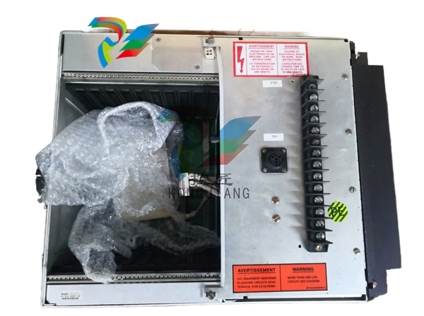
1. Apply a small amount of Never-Seez PN NG-165(GE PN 248A9779P001) to threads, prior
to reinstalling the Flame Sensor
2.Inspect the window and clean with Isopropanol soaked swab. If required install hand tight
(3-4 Full turs) tighten with a wrench approximately 2.5 turns.Tighten further as required to
align keys on cable connector with slots in sensor connector
3. Slide cooling coil over Flame Sensor major diameter and orient tubes on the coil as required
for assembly. Tighten clamps 50-60 in. lbs.Install Swagelok fittings re-torque damps to 50-
60 in. lbs. after first shut down
Note:50-60 in.lbs=5.6 - 6.8 Nm.When installing the Water Cooling Coil,ensure that the edge of the
Sheet Metal Band is not in contact with the cooling tubes. This will ensure that no rubbing or fretting of the
cooling tubes by the band's edge will occur during turbine operation.
The Flame Tracker™ is connected to the controller as a typical two wire current transmitter. It can be
operated from any well-filtered dc supply from 12 volts to 30 volts. The supply should be capable of supplying
100 milliamps.
The power supply must be protected to prevent the supply voltage from exceeding 30 volts in normal use
and more than 42 volts under transient conditions. The sensor is protected against reverse polarity. The
maximum value for the sense resistor plus the wire resistance is dependent on the supply voltage. At 24 volts
this value is 560 ohms. Resistance values for other voltages can be determined from the chart in Figure 2.
Figure 1 shows the preferred wiring for the sensor with the Rsense of the controller in the return line of the
sensor. This configuration can be used with controllers that have single ended inputs (one side of the input
grounded) or differential inputs (neither side of the input grounded). For pin outs and cable color code see
Figure 1.
3.3 CONNECTOR PINOUT
The pinout for the power connector is as follows:
CONNECTOR LEGEND
PIN CIRCUIT DESIGNATIONA -B +
C Ground
D Not Used
E Not Used
3.4 SENSOR CHECKOUT
Disconnect the sensors and unscrew them from the turbine. Plug the sensor cables back in to each of the
sensors. Apply power to the sensors. Check the current values at the controller for each of the sensors. The
sensors are sensitive to light, and may have some reading, depending on the ambient light level. Test each
sensor by covering the port to see the zero flame intensity signals, and with a flashlight to see a positive
reading. With no light the reading should be 3.7 to 4.1 milliamps, while with most flashlights the reading should
be above 8 milliamps. An LED flashlight may not work for this application. Variations in flashlight type,
strength, or battery voltage may cause variation in signal output. The flashlight test is intended as a field test
for general functionality only and is not a controlled or quantitative test. If a sensor is outside these rough
check limits see Section 5.0.
Disconnect the sensor cables, and reinstall the sensors according to the instruction in Section 3.1. At this
time step 2 of Section 3.1 should be completed and the sensor cables reconnected. Make sure that the
sapphire window is clean; if it needs cleaning, do this according to the maintenance instructions in Section 4.0.
Check that all sensors are reading between 3.7 to 4.1 milliamps.
3.5 CONTROLLER SETUP
The Flame Sensor provides a minimum output of 5 milliamps when exposed to the minimum flame intensity
specified in GE specification number 362A1052. The set point for flame off should be set to 6.25%, which
equals 5 milliamps. The set point for flame on should be 10%, which equals 5.6 milliamps. If the intensity
levels are to low for these settings their may be other
Purchase history
| User name | Member Level | Quantity | Specification | Purchase Date |
|---|
Total 0 Record
Related products
Customer Reviews
Satisfaction :
5 Stars
No evaluation information


- other
- LTI Drives
- ADLINK
- Beckhoff
- Other Brands
- AMAT
- Iba
- PEPPERL+FUCHS
- Aerotech
- WATLOW
- MAN
- ADVANCED
- Abaco
- YOKOGAWA
- KOLLMORGEN
- MEGGITT
- kong-sberg
- METSO
- Motorola
- NI
- OEMAX
- RELIANCE
- scanlab
- schneider
- uniop
- Vibro-Meter
- Honeywell
- Rolls-Royce
- MOOG
- GE
- B&R
- Woodward
- Yaskawa
- xYCOM
- Siemens
- Emerson
- HIMA
- Bently
- ZYGO
- FOXBORO
- OMACO
- PROSOFT
- ENTERASYS
- TRICONEX
- Parker
- Lenze
- KEBA
- Alstom
- CTI
- ABB
- A-B
145

-
 ADLINK PCI-9112/cPCI-9112 multifunctional acquisition card
 -
 ADLINK PCI-8102 Two Axis Pulse Motion Control Card
 -
 ADLINK PCI-9812/PCI-9810 synchronous 4-channel high-speed acquisition card
 -
 ADLINK PCI-7200/cPCI-7200 high-speed digital I/O board
 -
 ADLINK MXE-1000 series fanless embedded machine
 -
 ADLINK IMB-T10 Mini ITX Industrial Motherboard
 -
 ADLINK HSL Distributed High Speed I/O System
 -
 ADLINK PXI/DAQ/DAQe-2500 series multifunctional analog output DAQ card
 -
 ADLINK PXI/DAQ/DAQe-2200 series multifunctional data acquisition card
 -
 ADLINK ETX-AT ETX Core Computer Module
 -
 ADLINK ACL-7225 ISA 16 channel relay output+16 channel isolated digital input card
 -
 ADLINK DAQ-2000 series synchronous acquisition card
 -
 ADLINK NuPRO-E330 PICMG 1.3 full-length industrial motherboard (SHB)
 -
 ADLINK ACL-8112 series multifunctional ISA acquisition card
 -
 ADLINK USB-2405 24 bit dynamic signal acquisition module
 -
 ADLINK PXIS-3320 15 slot 6U PXI chassis
 -
 ADLINK PCIe GIE7x series acquisition card
 -
 ADLINK PCIe-7856/PCIe-7853 Distributed Motion and IO Main Controller PCIe Acquisition Card
 -
 ADLINK PCI-6308 series isolated analog output board
 -
 ADLINK PCI-7432 Isolated Digital I/O Acquisition Card
 -
 ADLINK NuPRO-E72 PICMG 1.3 Full length Industrial SHB Single Board Computer
 -
 ADLINK MXE-5400 series fanless embedded industrial computer
 -
 ADLINK M-322 Industrial ATX Motherboard
 -
 ADLINK IMB-M43H Industrial ATX Motherboard
 -
 ADLINK IMB-M42H Industrial ATX Motherboard
 -
 ADLINK i915GV-INA ATX motherboard
 -
 ADLINK ETX-NR667 Embedded ETX Standard Computer Module
 -
 ADLINK ETX-BT (PATA to SATA version) User Manual
 -
 ADLINK CM1-BT1 PC/104 Single Board Computer
 -
![ADLINK cPCI-8217 [R] 3U CompactPCI VGA/LCD Display Module](https://aosspic10001.websiteonline.cn/hkw632bc8/image/image_aJXQRn.png) ADLINK cPCI-8217 [R] 3U CompactPCI VGA/LCD Display Module
ADLINK cPCI-8217 [R] 3U CompactPCI VGA/LCD Display Module -
 ADLINK AmITX-SL-G Mini ITX Embedded Motherboard
 -
 ADLINK AmITX-AL-I ultra-thin Mini ITX industrial motherboard
 -
 ADLINK NuPRO-E315 Full length PICMG 1.3 Industrial SHB Single Board Computer
 -
 ADLINK NuPRO-842 Full length PICMG 1.0 PCI/ISA Industrial Single Board Computer
 -
 ADLINK NuPRO-900A PICMG 1.2 ePCI-X Dual Xeon Industrial System Motherboard (SHB)
 -
 ADLINK cPCI-6910 series 6U CompactPCI single board computer
 -
 ADLINK cPCI-6860A 6U CompactPCI dual core single board computer with cPCI-R6860A rear adapter board
 -
 ADLINK cPCI-8168 6U CompactPCI Eight Axis Motion Control Card
 -
 ADLINK NuPRO-E340 PICMG 1.3 Industrial SHB motherboard
 -
 ADLINK NuPRO-A40H Full length PICMG1.0 Industrial Single Board Computer (SBC)
 -
 ADLINK NuPRO-852 Full length PICMG1.0 Industrial Single Board Computer
 -
 ADLINK NuPRO-841 Full length Industrial SBC
 -
 ADLINK NuPRO-590/591/592 series Socket7 full-length industrial SBC
 -
 ADLINK MXE-5500 series fanless embedded industrial computer
 -
 ADLINK MXE-200/200i Fanless Embedded Machine
 -
 ADLINK cPCI-6770 series CompactPCI CPU board
 -
 ADLINK NuPRO-A301 standard PICMG 1.0 full-length industrial SBC single board computer
 -
 ADLINK NuPRO-965 PICMG 1.3 SHB Express Full length Industrial Motherboard
 -
 ADLINK NuPRO-935A Full length PICMG1.0 Industrial Single Board Computer
 -
 ADLINK NuPRO-865 Full length Single Board Computer
 -
 ADLINK NuPRO-840 DV/LV Full Length PICMG Industrial Single Board Computer
 -
 ADLINK NuPRO-770 series full-length industrial single board computer
 -
 ADLINK NuPRO-595 series half length Socket 7 industrial motherboard
 -
 ADLINK cPCI-6840 series 6U CompactPCI single board computer
 -
 Foxboro 43AP series pneumatic indicator controller (PSS 3-1B3 A)
 -
 ADLINK cPCI-3720 Series 3U Low Power CompactPCI Single Board Computer
 -
 ADLINK NuPRO-E47, PICMG 1.3 full-length industrial SHB system motherboard
 -
 ADLINK NuPRO-E43 PICMG 1.3 full-length system motherboard
 -
 ADLINK NuPRO-780 series full-length industrial CPU board
 -
 ADLINK cPCI-6965 series 6U CPCI single board computer
 -
 ADLINK USB/LPCI/LPCIe-3488A GPIB interface card
 -
 Rittal SK 3241.700 Blue e+Fan Filter Unit
 -
 ADLINK cPCI-8168 6U CompactPCI 8-Axis Motion Control Card
 -
 ADLINK PCIe PXIe-8638 PCIe to PXIe Bus Expansion Kit
 -
 ADLINK PCIe GIE7x series acquisition card
 -
 ADLINK PCIe-7396 96 96 channel TTL digital IO card
 -
 ADLINK PCI/MPC/PXI-8164 Three in One Motion Control Card
 -
 ADLINK PCI-8154 Four Axis Pulse Motion Control Card
 -
 ADLINK PCI-8134 Four Axis Servo/Stepper Motion Control Card
 -
 ADLINK NuPRO-E42 PICMG1.3 full-length SHB motherboard
 -
 ADLINK MXC-6600 series high-performance fanless extended industrial computer
 -
 ADLINK MXC-6000 series embedded industrial control computer
 -
 ADLINK MXC-2300 series fanless expandable embedded industrial computer
 -
 ADLINK MCM-204 Independent Ethernet DAQ User Manual
 -
 ADLINK MCM-100/102 Edge IoT Platform for Machine Condition Monitoring User’s Manual
 -
 ADLINK MXC-6400 series sixth generation Core Fanless Scalable Industrial Control Computer
 -
 ADLINK Matrix Full Series Fanless Embedded Industrial Control Computers
 -
 ADLINK GIE64+4-channel PoE Gigabit Vision Capture Card
 -
 Honeywell UMS Security System Troubleshooting Guide
 -
 Honeywell Expert Series-C I/O Module
 -
 ADLINK EOS-1200 Embedded Vision Host
 -
 ADLINK DLAP-5200 series high-performance fanless AI industrial computer
 -
 ADLINK DLAP-4000 series embedded industrial control computer
 -
 ADLINK Matrix MXC-2000 Series Fanless Industrial Control Computer Specification
 -
 ADLINK DAQ -/DAQE -/PXI-2000 Series Multi functional Synchronous Acquisition Card
 -
 ADLINK cPCI-6520 6U CompactPCI Single Board Computer
 -
 ADLINK CM1-86DX3 PC/104 Single Board Computer
 -
 Honeywell DC1000 series PID temperature controller
 -
 ALSTOM MiCOM C264 Modular Substation Controller
 -
 EMERSON AMS 2140 Mechanical Health Analyzer
 -
 ADLINK NuPRO-E320 PICMG1.3 Full length Industrial Motherboard
 -
 ADLINK NuPRO-800 Series Full length Industrial SBC User Manual
 -
 ADLINK NuPRO-598 Industrial Single Board Computer
 -
 ADLINK MXC-6300 Fanless Embedded Industrial Control Computer
 -
 ADLINK Express-BASE7 User Manual
 -
 ADLINK DLAP-211 Series Fanless Edge AI Platform Specification Manual
 -
 ADLINK PCI/LPCI/LPCIe/cPCI-723X series 32 channel isolated digital I/O card
 -
 ADLINK cPCI-6965 series 6U CompactPCI single board computer
 -
 ADLINK NuDAQ 7200 series high-speed digital I/O board
 -
 Linghua ADLINK DLAP Deep Learning Acceleration Platform Product Manual
 -
 DEIF TCM-2 thyristor control module
 -
 Installation Manual for DEIF MVR-200 Series Medium Voltage Protection Device
 -
 DEIF MDR-2 multifunctional differential relay
 -
 DEIF AOM-1 Analog Output Module
 -
 DEIF AGI 400 series industrial/marine touch screen
 -
 Installation Manual for DEIF BRW-1 Marine Wing Bridge Instrument
 -
 DEIF AGC200 Quick Start Guide
 -
 DEIF AGC Multi line 2 Generator Set ControllerProduct basic information
 -
 ABB SPA-ZC 400 Ethernet Gateway Installation and Debugging Manual
 -
 ABB REM 543/545 motor generator protection device
 -
 DEIF PPU 300 controller
 -
 DEIF Delomatic 4 Offshore/Ocean Platform Dedicated Generator Power Management System DM-4
 -
 DEIF Delomatic Modular Generator Set Integrated System
 -
 DEIF AGC-4 Mk II Generator Set Controller
 -
 DEIF AGC-4 diesel generator set integrated controller
 -
 DEIF Multi line 2 Series PPU Unit Power Management (PPM) Operation Manual
 -
 DEIF Multi line 2 V2.4X Installation Manual
 -
 Beckwith M-6280 Digital Capacitor Bank Controller
 -
 Beckwith M-3311 Transformer Protection Relay
 -
 Beckwith M-3311A Transformer Integrated Protection Device
 -
 Beckwith M-3310 Transformer Integrated Protection Device Specification
 -
 Beckwith M-0359 Syncrocloser Check Plus Application Guide for Synchronous Calibration Relay
 -
 Beckwith M-0293A On Load Tap changer Controller Application Guide
 -
 DEIF GPU-3 Synchronous/Asynchronous Generator Integrated Microcomputer Protection Controller
 -
 Installation Instructions for DEIF PPM-3
 -
 Beckwith M-3520 distributed power grid connected comprehensive protection device
 -
 Beckwith M-3430 generator comprehensive protection device
 -
 Beckwith M-2293B adapter panel

K-JIANG

Add: Jimei North Road, Jimei District, Xiamen, Fujian, China
Tell:+86-15305925923