

K-WANG


- Telephone:+86-15305925923
- contacts:Mr.Wang
- Email:wang@kongjiangauto.com
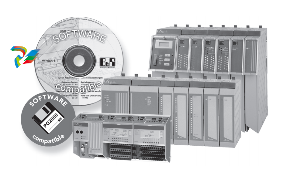
The B&R SYSTEM 2000 controller generation is an automation system which sets new standards for
performance, functionality and operational security.The B&R 2003, B&R 2005 and B&R 2010 systems
cover the entire application range, from simple logic controllers to complex decentralized automation
systems.
The systems have different structures, expandability, modularity and CPU performance. These systems are
very closely related and therefore meet the fundamentalrequirements for complete centralized and
decentralized compatibility for the programmer.
B&R-X20CPx48x-ENG-controller generation is
B&R SYSTEMS2003 Characteristics
Hardware:
Hardware modularity
Network capable
Communication interfaces to HMI
PCC and industrial computer functionality
EMC according to IEC 61131-2
Secure I/O bus protocol
Remote I/O points
Bit or word processing in a single cycle
All terminals for 2 or 3 line connection available directly on the module
No extra terminals needed
Software:
Multitasking operating system for PCC and industrial computer applications
Powerful PCC programming languages
High level language programming
Exact control over PCC timing
Simple programming software with window oriented user interface
●Project management using the programming software
PCC (programmable computer controller)
The core of the PCC consists of powerful standard computer components. The processors are supported by
RISC processors which allow fast processing of I/O signals.
Most CPUs use a modular interface concept Various bus or network systems can be integrated in the B&R
SYSTEM 2003 efficiently using plug-in interface modules.
The computer core uses components which provide the functionality of an industrial PCC. Bit, byte and word
access ispossible inasinglecycle whichincreasesspeed whencombiningPCC links andindustrial computer
functionality.
System Interface
The system interface is the sum ofall l/O modules, i.e. the interface between PCC and the machine/system
being controlled. All B&R SYSTEMS 2003 I/O modules are protected from extemal disturbances using
suitable EMC measures(IEC 61131-2 standard).
Length and structure of the l/O bus can be adjusted according to the requirements of the machine/system.
Thatmeansthe connectionpoints forI/O signals donothave tobe in the same location asthePCC CPU.Using
remote l/O bus segments (Remote I/O,CAN I/O) allows the optimal structure to be created for the respective
application. I/O modules are installed on the machine/system where they are needed. Cabling tothe core of
the PCC is reduced to a two conductor or fibre optic cable.
Network Capability
Network capability and the possibility to communicate with systems from other manufacturers have become
amustforall industrialcontrollers. TheB&R2000PCC familymeets manyof these requirements using system-
wide and multi-system communication possibilities.
Software Concept
Special attention was given to simple operation and programming.Standard PLC programs run cyclically, i.e.
the program is repeated in a loop. To increase efficiency, the B&R SYSTEM 2000 also offers the possibility
to use various tasks with different cycle times. In this way, critical program sections (e.g.reaction to trigger
signals) can be processed faster than the evaluation of slower events (e.g. polling keys).
Programming
The CPU is programmed using the programming systemPG2000 or Automation Studio™. Several program-
ming languages are available:
2.3 SUPPLY VOLTAGE
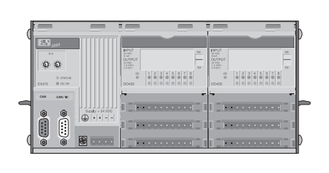
The supply voltage for the B&R 2003 control system is provided by a power supply integrated in the
controller.
2.4 TERMINAL BLOCKS
B&R 2003 modules use a large number of terminal blocks to make connections.
The pin assignments for the individual modules can be found in this manual (Chapter "B&R 2003 Modules").
The construction of the terminal blocks has the following advantages for the PCC user:
.Terminal blocksare easy to remove using two ejection leverson the module ordirectly ontheterminal
blocks.
·Most terminal blocks are available with screw clamps and also with cage clamps.
2.5 PROGRAM MEMORY MODULES
2.5.1 2003 PCC CPU
When using aB&R 2003 CPU,application programs and the operating system are stored in the CPU.
2.5.2 Remote Slaves
When used asa remote l/Oslave, the application programs are stored in the remote master (e.g.EX150).The
operating system is programmed in the remote I/O bus controller.
2.5.3 CAN Slaves
When used as a CAN slave,the application programs are stored in theCAN master (e.g.XP152).The
operating system is programmed in theCAN buscontroller. Configurationdatacanbeplaced inconfiguration
memory (inserted from the front).
The CAN bus controller EX270 is equipped with an internal S-EEPROM. Operating system parameters can
be stored in this S-EEPROM.
| User name | Member Level | Quantity | Specification | Purchase Date |
|---|


- LTI Drives
- other
- ADLINK
- Beckhoff
- Shinkawa
- Other Brands
- AMAT
- Iba
- PEPPERL+FUCHS
- Aerotech
- WATLOW
- MAN
- ADVANCED
- Abaco
- YOKOGAWA
- KOLLMORGEN
- MEGGITT
- kong-sberg
- METSO
- Motorola
- NI
- OEMAX
- RELIANCE
- scanlab
- schneider
- uniop
- Vibro-Meter
- Honeywell
- Rolls-Royce
- MOOG
- GE
- B&R
- Woodward
- Yaskawa
- xYCOM
- Siemens
- Emerson
- HIMA
- Bently
- ZYGO
- FOXBORO
- OMACO
- PROSOFT
- ENTERASYS
- TRICONEX
- Parker
- Lenze
- KEBA
- Alstom
- CTI
- ABB
- A-B

-
 SIGMATEK TAE 1941 Touch Display Unit
 -
 SIGMATEK TAE 151 Touch Display Unit
 -
 SIGMATEK AKM series servo motor
 -
 SIGMATEK S-DIAS Control System
 -
 SIGMATEK Human Machine Interface (HMI)
 -
 SIGMATEK DIAS Drive 310-23 servo amplifier
 -
 SIGMATEK CCP 521 C-DIAS processor module
 -
 MEGMEET L6 series electric drive
 -
 Sysmex XN-1000/XN-2000 Hematology Analyzer
 -
 Sysmex XN-L series (XN-530/XN-430/XN-330) fully automatic blood cell analyzer
 -
 Sysmex XN-9000 Series Fully Automated Blood Analysis Pipeline
 -
 LTI‑Motion ServoOne Field Bus Systems PROFIBUS and PROFINET
 -
 Micro Innovation MICRO PANEL GF1 Color Touch Human Computer Interface
 -
 Micro Innovation WINbloc Distributed Remote I/O System
 -
 Micro Innovation MICRO PANEL GS-2 Industrial Touch Visualization Operation Panel (HMI)
 -
 LTi LST/LSH series synchronous servo motor
 -
 LTi CDE/CDB3000 positioning controller
 -
 ENOTEC SILOTEC ® Installation and Operation Instructions for 8000 Silo Monitoring O ₂/CO ₑ Analyzer System
 -
 ENOTEC ENSITU ® 7000 Compact Oxygen Transmitter Probe
 -
 ENOTEC COMTEC ® Installation and Operation Instructions for 6000 ATEX GasEx Explosion proof O ₂/COE Analyzer System
 -
 ENOTEC Integrated Products
 -
 ENOTEC OXITEC ® 500E Extraction Oxygen Analyzer
 -
 KUKA KR CS Box-2 Compact Controller for Four Axis SCARA Robot
 -
 KUKA KR C5 slim-2 Robot Controller
 -
 KUKA KR C5 micro With KUKA System Software (KSS/VSS) Assembly Instructions
 -
 KUKA KR C5 micro controller
 -
 KUKA KR C5 Controller Assembly Instructions
 -
 KUKA KR C5 compactcab and KR C5 small-size cab cabinets
 -
 KUKA KR C4 smallsize-2 small robot control cabinet
 -
 KUKA KR C4 Midsize/KR C4 Midsize CK Assembly Manual
 -
 ENOTEC ® Installation and Operation Instructions for 5000/5000+Oxygen Analyzer System
 -
 KUKA KR C4 extended; KR C4 extended CK Assembly Instructions Assembly Manual
 -
 Assembly/Installation Manual for KUKA KR C4 Compact Control Cabinet
 -
 KUKA Sunrise Cabinet Med Medical Collaborative Robot Special Control Cabinet
 -
 KUKA Sunrise Cabinet Next Generation Small Control Cabinet
 -
 KUKA KR C4 Smallsize-2 family's smallest control cabinet
 -
 KUKA KR C4 midsize; KR C4 midsize CK medium-sized control cabinet
 -
 KUKA KR C4 extended is a high-power multi axis control cabinet
 -
 General installation and operation instructions for KUKA KR C4 and KR C4 CK controllers
 -
 KUKA KR C4 compact controller operation instructions
 -
 Installation and Operation Instructions for KUKA Robot Arm
 -
 KUKA TITAN-2 Ultra Ground Overloading Six Axis Robot
 -
 Assembly instructions for KUKA KR SCARA-2 CS series robotic arm body
 -
 KUKA MA KR SCARA X Installation Guide
 -
 KUKA KR FORTEC-2 Ultra Heavy duty Ground Six Axis Robot Mechanical Assembly Manual
 -
 KUKA KR FORTEC-2 new generation heavy-duty ground six axis robot
 -
 KUKA Robots KR 1000 titan; KR 1000 L750 titan With F Variants Assembly Instructions
 -
 KUKA KR 600 FORTEC heavy-duty six axis ground mounted industrial robot
 -
 KUKA KR 500 MT FORTEC Heavy duty Six Axis Industrial Robot
 -
 KUKA KR 360 FORTEC Heavy duty Six Axis Industrial Robot
 -
 KUKA Sunrise Cabinet Med Medical Edition Robot Controller User Manual
 -
 KUKA Robots KR SCARA HO Assembly Instructions
 -
 KUKA Robots KR QUANTEC-2 PA Assembly Instructions
 -
 KUKA Robots KR QUANTEC-2 K and KR QUANTEC-2 P With K-F and P-C Variants Assembly Instructions
 -
 KUKA Robots KR QUANTEC-2 HO Assembly Instructions
 -
 KUKA Robots KR QUANTEC-2 HC Assembly Instructions
 -
 KUKA KR QUANTEC-2 series heavy-duty ground mounted six axis industrial robot
 -
 KUKA KR QUANTEC PA series heavy-duty palletizing robot
 -
 KUKA KR IONTEC-2 series six axis industrial robot
 -
 KUKA KR IONTEC ultra series six axis heavy-duty industrial robot
 -
 KUKA KR IONTEC HO Robot Assembly Manual
 -
 KUKA Robots KR CYBERTECH-3 HW Assembly Instructions
 -
 KUKA Robots KR CYBERTECH-3 Assembly Instructions
 -
 KUKA Robots KR CYBERTECH-2 arc Assembly Instructions
 -
 KUKA Robots KR CYBERTECH nano-2 Assembly Instructions
 -
 KUKA KR CYBERTECH CR HO (KR 20 R1810-HO) assembly instructions
 -
 KUKA Robots KR CYBERTECH With F variant Assembly Instructions
 -
 KUKA KR CYBERTECH CR (KR 20 R1810-CR) Clean Room (CR) Version 6-Axis Industrial Robot
 -
 KUKA KR AGILUS-3 ultra series small six axis serial robot
 -
 KUKA KR 300 R2700-2 C-F Cast Ceiling Mounted 6-Axis Heavy duty Industrial Robot
 -
 KUKA KR 20 R1820-2 E Six Axis Industrial Robot
 -
 Assembly instructions for KUKA KR AGILUS-3 small six axis robot
 -
 KUKA KR AGILUS-2 New Generation Small Six Axis Robot
 -
 KUKA KR 1000 1300 titan PA; KR 1000 L950 titan PA With F Variants Assembly Instructions
 -
 KUKA KR 700 PA/KR 700 PA Arctic Installation Guide
 -
 KUKA KR 18 R1450-3 PP six axis ground mounted industrial robot
 -
 KUKA 12 SCARA Series 4-axis SCARA Horizontal Joint Robot
 -
 KUKA KR 4 R600 Small Six Axis Industrial Robot
 -
 Installation Guide for KUKA KR 3 R540 Small 6-Axis Industrial Robot
 -
 KUKA LBR iiwa CR Clean 7-Axis Lightweight Collaborative Robot
 -
 KUKA KR AGILUS sixx series six axis industrial robot operation instructions
 -
 KUKA 4-axis heavy-duty SCARA horizontal multi joint robot KR 60 R1200 Z400 CS
 -
 KUKA KR 23 SCARA-2 CS SCARA Horizontal Multi Joint Robot
 -
 KUKA KR 20 SCARA CS Robot Assembly Instructions
 -
 KUKA KR 15 DELTA-2 Assembly Manual
 -
 KUKA KR 13 SCARA-2 CS Assembly Manual
 -
 KUKA KR 3 D1200 (Standard Delta Robot) Assembly Instructions
 -
 KUKA KR 3 D1200 HM Assembly Manual
 -
 KUKA LBR Med 7 R800, LBR Med 14 R820 Medical Edition Robot
 -
 KUKA Robots LBR iiwa 7 R800, LBR iiwa 14 R820 Operating instructions
 -
 KUKA LBR iiwa CR (Clean Room Version Robot) Operating Instructions
 -
 Lauer PCStopline series text operation panel
 -
 KUKA LBR iisy (MA_LBR_iisy V5) assembly manual
 -
 KUKA LBR iisy 3 R760 Assembly Manual
 -
 KUKA LBR iico Collaborative Robot Assembly Manual
 -
 Lauer LCAstarline (LCA300/LCA320/LCA325) Text Display Screen
 -
 Lauer PCS950/PCS950c/PCS950e operation console
 -
 Lauer EPC Series Industrial Embedded Human Computer Integrated PC User Guide
 -
 Bonfiglioli Precision Planetary Gearbox TIR-STD ENG R07
 -
 Bonfiglioli ACT/ACU Cold Plate Inverter Installation Instructions
 -
 Bonfiglioli EM-RES-02 Expansion Module
 -
 Bonfiglioli EM-RES-01 Expansion Module
 -
 Bonfiglioli EM-IO-04 Expansion Module
 -
 Bonfiglioli EM-IO-03 Expansion Module
 -
 Bonfiglioli EM-IO-02 Expansion Module
 -
 Bonfiglioli Vectron EM-IO-01 Expansion Module
 -
 Bonfiglioli F series gearbox
 -
 Installation, operation, maintenance, and spare parts of Bonfiglioli HF series reducers
 -
 Installation, Operation, and Maintenance of Bonfiglioli 300-300M Series ATEX Reducer
 -
 Bonfiglioli R3 series planetary gearbox
 -
 Bonfiglioli C series inline helical gear explosion-proof reducer
 -
 Bonfiglioli EM-ENC-05 Expansion Module
 -
 Bonfiglioli EM-ENC-04 Expansion Module
 -
 Bonfiglioli EM-ENC-03 Expansion Module
 -
 Bonfiglioli EM-ENC-02 Expansion Module
 -
 Bonfiglioli CM-CAN CANopen communication module
 -
 Bonfiglioli EM-SYS System Bus Expansion Module
 -
 Bonfiglioli CM-PDP Profibus DP Communication Module
 -
 Bonfiglioli CM-232/CM-485/CM-485T Modbus Communication Manual
 -
 Bonfiglioli BMS series precision planetary servo reduction motor
 -
 Bonfiglioli ACTION series ACT210 (230V), ACT410 (400V) frequency converter operation manual
 -
 Bonfiglioli ACT series frequency converter
 -
 Bonfiglioli HDP/HDO series gear unit IOM installation, operation and maintenance instructions
 -
 Installation, operation, and maintenance of Bonfiglioli 300-300M series reducers
 -
 Bonfiglioli 300M Modular planetary gearboxe
 -
 Bonfiglioli 3/H series heavy-duty modular gearbox
 -
 Bonfiglioli KRG-KCG-KSD hydraulic coupling
 -
 Bonfiglioli Vectron BTD-BCR servo motor

K-JIANG

Add: Jimei North Road, Jimei District, Xiamen, Fujian, China
Tell:+86-15305925923