
K-WANG
+086-15305925923
Service expert in industrial control field!


Product
Article
NameDescriptionContent
Adequate Inventory, Timely Service
pursuit of excellence


Ship control system
Equipment control system
Power monitoring system
Brand
Product parameters
- Telephone:+86-15305925923
- contacts:Mr.Wang
- Email:wang@kongjiangauto.com
Description
The REF601 is a dedicated feeder protection and control relay.
The REJ601 is an overcurrent protection relay without breaker
control. These relays are intended for the protection of utility
substations and industrial power systems within primary and
secondary distribution networks. They are members of ABB’s
Relion® product family and part of its 605 series.
ABB REF601 Feeder protection and control
1. Description
The REF601 is a dedicated feeder protection and control relay.
The REJ601 is an overcurrent protection relay without breaker
control. These relays are intended for the protection of utility
substations and industrial power systems within primary and
secondary distribution networks. They are members of ABB’s
Relion® product family and part of its 605 series.
These relays, provide an optimized composition of protection,
monitoring and control functionality in one unit, with the best
performance usability in its class and are based on ABB’s in depth knowledge of protection and numerical technology.
2. Relay functions
The REF601 and REJ601 can be pre-configured which facilita tes easy and fast commissioning of switchgear.
To emphasize the simplicity of using these relays, only applica tion specific parameters need to be set within the relay’s inten ded area of application. The standard signal configuration can
be altered by LHMI (local human-machine interface).
The relays are available in three alternative application configu rations, as indicated in Table 2.
Table 1. Standard configurations
Description Relay type
Feeder protection and control REF601
Overcurrent/Feeder protection REJ601
Table 2. Application configurations and supported functions
REJ601/ REF601 REJ601/ REF601 REF601
Functionality ANSI IEC B C D
Protection
Non-directional overcurrent protection, low-set stage 51P 3I> ● ●●
Non-directional overcurrent protection, high-set stage 50P-1 3I>> ● ●●
Non-directional overcurrent protection, instantaneous stage 50P-2 3I>>> ● ●●
Ground-fault protection, low-set stage 51N Io> ● ●●
Ground-fault protection, high-set stage 50N Io>> ● ●●
Three-phase transformer inrush detector 68 3I2f> ● ●●
Three-phase thermal overload protection for feeders, cables and
distribution transformers
49 3Ith> - ● ●
Phase discontinuity protection 46PD I2/I1> - ● ●
Negative-sequence overcurrent protection 46 I2> - - ●
Circuit breaker failure protection 50BF/50NBF 3I>BF/
Io>BF
- ● ●
Master trip 94/86 Master Trip ● ●●
Two setting groups ● ●●
Control (Function only available in REF601)
Breaker control functionality 52CB I <-> O CB ● ●●
Auto-reclosing, 4 shots 79 O -> I - - ●
Condition monitoring
Trip circuit supervision TCM TCS ● ●●
Measurement
Three-phase current measurement 3I 3I ● ●●
Residual current measurement IN Io ● ●●
Negative phase sequence current I2 I2 - - ●
Thermal level θ ϑ - ● ●
Operation counter - - - ● ●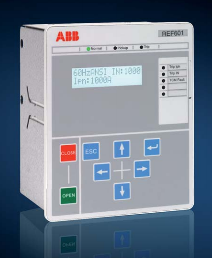
3. Protection functions
The REF601 and REJ601 offer three-stage overcurrent and two stage ground-fault protection functions. The transformer inrush
detector function is incorporated to prevent unwanted tripping
due to energizing of transformers.
The REF601 and REJ601 offer three-stage overcurrent and
two-stage ground fault protection functions. The low-set stages
for overcurrent and ground fault protection are equipped with
selectable characteristics – Definite Time (DT) and Inverse De finite Minimum Time (IDMT). The relays feature standard IDMT
characteristics according IEC 61255-3 - Normal Inverse, Very
Inverse, Extremely Inverse, Long-time Inverse. They also feature
characteristics according to ANSI C37.112 - Moderate Inverse,
Normal Inverse, Very Inverse, and Extremely Inverse. The relays
also have a special characteristic RI Inverse (RI) for better coor dination with the rest of the network. Additionally the relays also
support two setting groups.
The REF601 and REJ601 also offer thermal overload protection
for feeders, cables and transformers. Other protections inclu de negative phase sequence protection, phase discontinuity
protection and circuit breaker failure protection. The relays also
have an auto-recloser option for overhead line feeders.
4. Application
The REF601 and REJ601 are protection relays aimed at pro tection and control of incoming and outgoing feeders in MV
distribution substations. They can be applied for short-circuit,
overcurrent and ground-fault protection of overhead lines and
cable feeders of distribution and sub-distribution networks.
The inrush current stabilization function allows the relays to be
used as the main protection for distribution transformers.
The relay with application configuration B offers non-directional
overcurrent and ground-fault protection. The residual current for
the ground-fault protection is derived from the phase currents.
When applicable, core-balance current transformers can be
used for measuring the residual current, especially when sensiti ve ground-fault protection is required.
The application configuration C adds thermal overload protec tion for feeders, cables and transformers, phase discontinuity
protection and circuit breaker failure protection.
The application configuration D provides the highest functionali ty with incorporation of negative phase sequence protection and
a multi-shot auto-recloser function making the relay suitable for
overhead line feeders.
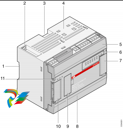
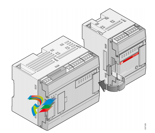
5. Optimized for limited space
With their compact size and unique technical features, the
REF601 and REJ601 are ideal for retrofits, compact switchgear
and switchgear with limited space. These relays have a small
mounting depth and do not have any loose mounting accesso ries. Uniquely, the REF601 and REJ601 use a press-fit mounting
arrangement, suitable for quick and easy installation on switch gear
6. Control
The REF601 features control of one circuit breaker with dedica ted push-buttons and guidance on local HMI for opening and
closing. It includes two dedicated outputs for breaker control.
The breaker control is also possible through optional MODBUS
RTU or IEC 60870-5-103 communication.
7. Measurement
All versions of the relay continuously measure phase currents
and ground current. Ground current can be measured using an
external zero sequence current transformer or can be calculated
internally.
During operation, the default view of display shows the highest
loaded phase current in primary terms (Amps) and the ground
current. The values measured can be accessed locally via the
user interface on the relay or remotely via the communication
interface of the relay.
These relays continuously measure negative sequence current,
thermal level and counter values if these functions are suppor ted as per application configurations.
8. Event log
To collect sequence of events (SoE) information, the relays
incorporate non-volatile memory with a storage capacity of 100
events with associated time stamps and a resolution of 1 ms.
The event log includes trip circuit monitoring status, protection
operation status, binary I/O status and relay fault code. The
event logs are stored sequentially, the most recent being first
and so on. The non-volatile memory retains its data in the event
of temporary auxiliary supply loss.
The event log facilitates detailed post-fault analysis of feeder
faults and disturbances. The SoE information can be accessed
locally via the user interface on the relay front panel or remotely
via the communication interface of the relay.
9. Recorded data
The relays store fault records of analog values for the last five
trip events in non-volatile memory. The fault recording is trigge red by the trip signal of a protection function. Each fault record
includes the current values for three phases and ground current
along with a time stamp. These records enable the user to ana lyze the five most recent power system events.
The relays record the number of phase and ground fault trip
events into dedicated trip counters. These trip counters cannot
be reset by the user and are stored in non-volatile memory.
The recorded information can be accessed locally via the user
interface on the relay front panel and can be uploaded for sub sequent fault analysis.
10. Self-supervision and test function
The relay’s built-in self-supervision system continuously mo nitors the state of the relay hardware and the operation of the
relay software. Any fault or malfunction detected will signal an
alert for the operator. A permanent relay fault will block the pro tection functions of the relay to prevent incorrect relay operati on.
The relays support a built-in test mode which enables the user
to test the relay HMI and binary outputs.
11. Trip-circuit monitoring
The trip-circuit monitoring continuously monitors the availability
and operability of the trip circuit. It provides open-circuit monito ring both when the circuit breaker is in its closed and in its open
position. It also detects loss of circuit-breaker control voltage.
12. Access control
To protect from unauthorized access and to maintain the
integrity of information, the relays are armed with a three level,
role-based user authentication system with individual pass words for operator, engineer and administrator levels. There
are two alternative password protection options. The default
is a combination of different navigation keys. The alternative is
an alpha-numeric password. The user can select the password
option based on their requirement.
Purchase history
| User name | Member Level | Quantity | Specification | Purchase Date |
|---|
Total 0 Record
Related products
Customer Reviews
Satisfaction :
5 Stars
No evaluation information


- other
- ADLINK
- LTI Drives
- Other Brands
- AMAT
- Iba
- PEPPERL+FUCHS
- Aerotech
- WATLOW
- MAN
- ADVANCED
- Abaco
- YOKOGAWA
- KOLLMORGEN
- MEGGITT
- kong-sberg
- METSO
- Motorola
- NI
- OEMAX
- RELIANCE
- scanlab
- schneider
- uniop
- Vibro-Meter
- Honeywell
- Rolls-Royce
- MOOG
- GE
- B&R
- Woodward
- Yaskawa
- xYCOM
- Siemens
- Emerson
- HIMA
- Bently
- ZYGO
- FOXBORO
- OMACO
- PROSOFT
- ENTERASYS
- TRICONEX
- Parker
- Lenze
- KEBA
- Alstom
- CTI
- ABB
- A-B
172

-
 ADLINK NuPRO-840 DV/LV Full Length PICMG Industrial Single Board Computer
 -
 ADLINK NuPRO-770 series full-length industrial single board computer
 -
 ADLINK NuPRO-595 series half length Socket 7 industrial motherboard
 -
 ADLINK cPCI-6840 series 6U CompactPCI single board computer
 -
 Foxboro 43AP series pneumatic indicator controller (PSS 3-1B3 A)
 -
 ADLINK cPCI-3720 Series 3U Low Power CompactPCI Single Board Computer
 -
 ADLINK NuPRO-E47, PICMG 1.3 full-length industrial SHB system motherboard
 -
 ADLINK NuPRO-E43 PICMG 1.3 full-length system motherboard
 -
 ADLINK NuPRO-780 series full-length industrial CPU board
 -
 ADLINK cPCI-6965 series 6U CPCI single board computer
 -
 ADLINK USB/LPCI/LPCIe-3488A GPIB interface card
 -
 Rittal SK 3241.700 Blue e+Fan Filter Unit
 -
 ADLINK cPCI-8168 6U CompactPCI 8-Axis Motion Control Card
 -
 ADLINK PCIe PXIe-8638 PCIe to PXIe Bus Expansion Kit
 -
 ADLINK PCIe GIE7x series acquisition card
 -
 ADLINK PCIe-7396 96 96 channel TTL digital IO card
 -
 ADLINK PCI/MPC/PXI-8164 Three in One Motion Control Card
 -
 ADLINK PCI-8154 Four Axis Pulse Motion Control Card
 -
 ADLINK PCI-8134 Four Axis Servo/Stepper Motion Control Card
 -
 ADLINK NuPRO-E42 PICMG1.3 full-length SHB motherboard
 -
 ADLINK MXC-6600 series high-performance fanless extended industrial computer
 -
 ADLINK MXC-6000 series embedded industrial control computer
 -
 ADLINK MXC-2300 series fanless expandable embedded industrial computer
 -
 ADLINK MCM-204 Independent Ethernet DAQ User Manual
 -
 ADLINK MCM-100/102 Edge IoT Platform for Machine Condition Monitoring User’s Manual
 -
 ADLINK MXC-6400 series sixth generation Core Fanless Scalable Industrial Control Computer
 -
 ADLINK Matrix Full Series Fanless Embedded Industrial Control Computers
 -
 ADLINK GIE64+4-channel PoE Gigabit Vision Capture Card
 -
 Honeywell UMS Security System Troubleshooting Guide
 -
 Honeywell Expert Series-C I/O Module
 -
 ADLINK EOS-1200 Embedded Vision Host
 -
 ADLINK DLAP-5200 series high-performance fanless AI industrial computer
 -
 ADLINK DLAP-4000 series embedded industrial control computer
 -
 ADLINK Matrix MXC-2000 Series Fanless Industrial Control Computer Specification
 -
 ADLINK DAQ -/DAQE -/PXI-2000 Series Multi functional Synchronous Acquisition Card
 -
 ADLINK cPCI-6520 6U CompactPCI Single Board Computer
 -
 ADLINK CM1-86DX3 PC/104 Single Board Computer
 -
 Honeywell DC1000 series PID temperature controller
 -
 ALSTOM MiCOM C264 Modular Substation Controller
 -
 EMERSON AMS 2140 Mechanical Health Analyzer
 -
 ADLINK NuPRO-E320 PICMG1.3 Full length Industrial Motherboard
 -
 ADLINK NuPRO-800 Series Full length Industrial SBC User Manual
 -
 ADLINK NuPRO-598 Industrial Single Board Computer
 -
 ADLINK MXC-6300 Fanless Embedded Industrial Control Computer
 -
 ADLINK Express-BASE7 User Manual
 -
 ADLINK DLAP-211 Series Fanless Edge AI Platform Specification Manual
 -
 ADLINK PCI/LPCI/LPCIe/cPCI-723X series 32 channel isolated digital I/O card
 -
 ADLINK cPCI-6965 series 6U CompactPCI single board computer
 -
 ADLINK NuDAQ 7200 series high-speed digital I/O board
 -
 Linghua ADLINK DLAP Deep Learning Acceleration Platform Product Manual
 -
 DEIF TCM-2 thyristor control module
 -
 Installation Manual for DEIF MVR-200 Series Medium Voltage Protection Device
 -
 DEIF MDR-2 multifunctional differential relay
 -
 DEIF AOM-1 Analog Output Module
 -
 DEIF AGI 400 series industrial/marine touch screen
 -
 Installation Manual for DEIF BRW-1 Marine Wing Bridge Instrument
 -
 DEIF AGC200 Quick Start Guide
 -
 DEIF AGC Multi line 2 Generator Set ControllerProduct basic information
 -
 ABB SPA-ZC 400 Ethernet Gateway Installation and Debugging Manual
 -
 ABB REM 543/545 motor generator protection device
 -
 DEIF PPU 300 controller
 -
 DEIF Delomatic 4 Offshore/Ocean Platform Dedicated Generator Power Management System DM-4
 -
 DEIF Delomatic Modular Generator Set Integrated System
 -
 DEIF AGC-4 Mk II Generator Set Controller
 -
 DEIF AGC-4 diesel generator set integrated controller
 -
 DEIF Multi line 2 Series PPU Unit Power Management (PPM) Operation Manual
 -
 DEIF Multi line 2 V2.4X Installation Manual
 -
 Beckwith M-6280 Digital Capacitor Bank Controller
 -
 Beckwith M-3311 Transformer Protection Relay
 -
 Beckwith M-3311A Transformer Integrated Protection Device
 -
 Beckwith M-3310 Transformer Integrated Protection Device Specification
 -
 Beckwith M-0359 Syncrocloser Check Plus Application Guide for Synchronous Calibration Relay
 -
 Beckwith M-0293A On Load Tap changer Controller Application Guide
 -
 DEIF GPU-3 Synchronous/Asynchronous Generator Integrated Microcomputer Protection Controller
 -
 Installation Instructions for DEIF PPM-3
 -
 Beckwith M-3520 distributed power grid connected comprehensive protection device
 -
 Beckwith M-3430 generator comprehensive protection device
 -
 Beckwith M-2293B adapter panel
 -
 Beckwith M-2001C digital on load voltage regulator controller
 -
 Beckwith M-2001B Digital On Load Voltage Regulating Controller
 -
 Beckwith M-0388/M-0389 synchronous verification relay
 -
 Beckwith M-0193B synchronous closing device
 -
 Beckwith M-0115A Transformer Parallel Balancing Module
 -
 Beckwith M-0067E on load tap changer controller
 -
 Beckwith M-4272 Digital Motor Bus Switching System
 -
 Beckwith M-3311A Transformer Integrated Protection Device
 -
 Beckwith M-3425A Generator Integrated Protection Device Manual
 -
 Basler BE1-27/BE1-59/BE1-27/59 undervoltage/overvoltage relay
 -
 Basler AVC63-12/AVC125-10 excitation voltage regulator
 -
 Basler L301kc Color Three Line Array Camera Operation Manual
 -
 Basler CBS 212A Current Enhanced Excitation System
 -
 Basler BE3-25 synchronous check relay
 -
 Operation Manual for Basler BE1-32R/BE1-32O/U Direction Power Relay
 -
 Basler Electric PRS-250 Veri Sync Synchronous Relay
 -
 Basler Pilot Series Area Array Industrial Camera piA2400-17gc
 -
 Basler BE1-11g comprehensive protection device for generator
 -
 Basler VR63-4C/UL Analog Excitation Voltage Regulator
 -
 Basler BE1-DFPR distribution feeder protection relay
 -
 Basler CBS310/CBS320 current strong excitation system
 -
 Basler UFOV250A/UFOV260A Low Frequency Overvoltage Module
 -
 Basler MVC104/MVC108/MVC232 manual voltage control device
 -
 Basler XR2002/XR2002F PMG excitation regulator
 -
 Basler DECS-400 Digital Excitation Control System
 -
 Basler DGC-2020 Digital Generator Set Controller
 -
 Basler MVC-300 Electronic Manual Excitation Controller
 -
 Basler MVC-104/MVC-108/MVC-232 manual excitation controller
 -
 Basler SSR32-12/SSR63-12/SSR125-12 Static Excitation Voltage Regulator
 -
 Basler SR4A/SR8A Analog Excitation Voltage Regulator
 -
 Basler BE2000E Digital Excitation Voltage Regulator
 -
 Basler DECS-2100 Digital Excitation System
 -
 Basler BE1-851 Overcurrent Protection Device Manual
 -
 Basler APR 63-5 Voltage Regulator
 -
 Basler BE1-FLEX Integrated Protection Control System
 -
 Basler BE1-700V digital voltage protection relay
 -
 Basler BE1-87B high impedance bus differential relay
 -
 Basler BE1-40Q demagnetization relay
 -
 Basler BE1-60 Voltage Balance Relay
 -
 Basler BE1-47N negative sequence voltage phase sequence relay
 -
 Basler BE1-81O/U digital frequency relay
 -
 Basler BE1-11f Feedline Integrated Protection Device Manual
 -
 Basler DECS-250 Digital Excitation Control System
 -
 Basler DECS-100 Digital Excitation Control System
 -
 Basler BE1-BPR Circuit Breaker Protection Relay
 -
 Basler BE1-50/51B-255 overcurrent relay
 -
 Basler BE1-25 synchronous check relay
 -
 Basler BE1-51 microcomputer time limited overcurrent relay
 -
 Basler DECS-300 Digital Excitation Control System
 -
 Mitsubishi MELSEC-F FX series programmable controllers

K-JIANG

Add: Jimei North Road, Jimei District, Xiamen, Fujian, China
Tell:+86-15305925923