
K-WANG
+086-15305925923
Service expert in industrial control field!


Product
Article
NameDescriptionContent
Adequate Inventory, Timely Service
pursuit of excellence


Ship control system
Equipment control system
Power monitoring system
Brand
Product parameters
- Telephone:+86-15305925923
- contacts:Mr.Wang
- Email:wang@kongjiangauto.com
Description
The Profibus and DeviceNet Network Interfaces are also available with built-in I/O to
reduce cost and footprint. The network interfaces can be expanded and support all of
the RSTi I/O types.
GE STXPBS032 Network Interfaces with Built-in I/O
Industrial I/OThe Profibus and DeviceNet Network Interfaces are also available with built-in I/O to
reduce cost and footprint. The network interfaces can be expanded and support all of
the RSTi I/O types.
Network Interfaces with Built-in I/O
STXPBS032 STXPBS132 STXPBS232
Product Name Slave Network Interface with
32 Positive Logic Inputs Built-in
Slave Network Interface with
32 Negative Logic Inputs Built-in
Slave Network Interface with
32 Sink Outputs Built-in
Lifecycle Status Active Active Active
Module Type Slave Network Interface Slave Network Interface Slave Network Interface
Field Busses/Device Networks Profibus V1 Profibus V1 Profibus V1
Protocol Supported
Freeze mode, Sync mode,
Auto baudrate, Fail safe mode
Freeze mode, Sync mode,
Auto baudrate, Fail safe mode
Freeze mode, Sync mode
Auto baudrate, Fail safe mode
Features
Profibus DP Network Slave has
built-in 32 Positive Logic Inputs
with expansion support
Profibus DP Network Slave has
built-in 32 Negative Logic Inputs
with expansion support
Profibus DP Network Slave has
built-in 32 Sink Outputs
with expansion support
Baud Rate 9.6K to 12Mbps 9.6K to 12Mbps 9.6K to 12Mbps
I/O Data Size
Total: Inputs 36 bytes/Outputs 36 bytes total
(4 bytes In/ 4 bytes Out for base module and
32 bytes In/32 bytes Out for expansion
modules); Discrete I/O: Maximum Discrete
I/O: 256 inputs/ 256 outputs; Analog I/O:
16 Channels In/ 16 Channels Out
Total: Inputs 36 bytes/Outputs 36 bytes total
(4 bytes In/ 4 bytes Out for base module and
32 bytes In/32 bytes Out for expansion
modules); Discrete I/O: Maximum Discrete
I/O: 256 inputs/ 256 outputs; Analog I/O:
16 Channels In/ 16 Channels Out
Total: Inputs 36 bytes/Outputs 36 bytes total
(4 bytes In/ 4 bytes Out for base module and
32 bytes In/32 bytes Out for expansion
modules); Discrete I/O: Maximum Discrete
I/O: 256 inputs/ 256 outputs; Analog I/O:
16 Channels In/ 16 Channels Out
LEDs Module Status, Network Status, I/O Status Module Status, Network Status, I/O Status Module Status, Network Status, I/O Status
Diagnostic Supported Yes Yes Yes
Maximum Bus Length 100 meters to 1.2Km depending on baud rate 100 meters to 1.2Km depending on baud rate 100 meters to 1.2Km depending on baud rate
Maximum Number of Nodes Supported 100 100 100
Number of Expansion I/O Supported 8 8 8
Number of Points 32 32 32
System Power Requirement 24 VDC (19.2 to 28.8 VDC) with Current
Limit, Reverse Polarity Protection
24 VDC (19.2 to 28.8 VDC) with Current
Limit, Reverse Polarity Protection
24 VDC (19.2 to 28.8 VDC) with Current
Limit, Reverse Polarity Protection
Field Power Requirement 24 VDC (11 VDC to 28.8 VDC) 24 VDC (11 VDC to 28.8 VDC) 24 VDC (11 VDC to 28.8 VDC)
Input Type 32 Point 24 VDC Positive Logic 32 Point 24 VDC Negative Logic
Input Voltage Range 24 VDC (11 VDC to 28.8 VDC) 24 VDC (11 VDC to 28.8 VDC)
Input Impedance ~5.4K ohms ~5.4K ohms
Input Signal Delay < 0.5msec < 0.5msec
Response Time (ms) < 0.3msec
Trigger Voltage ON State: 9 VDC, OFF State: 5 VDC ON State: 9 VDC, OFF State: 5 VDC
Points per Common 32 32 32
Output Type 32 Point 24 VDC Negative Logic
Output Range Nominal 0 VDC; 11 to 28.8 VDC
Protection Short protection, Over Temperature
Protection, Over Current Limit
Minimum Output Load
Load Current per Point
0.5 Amps per point
Output Inrush Current
Polarity Sink
Configuration Tool GSM File GSM File GSM File
Interface Connector Type DB 9 connector (RS-485) DB 9 connector (RS-485) DB 9 connector (RS-485)
Power Dissipation 50 mA typical @ 24 VDC 50 mA typical @ 24 VDC 50 mA typical @ 24 VDC
Connector Type
Spring Clamp Terminal Block Spring Clamp Terminal Block Spring Clamp Terminal Block
Internal Power Used (5 VDC loading) 400 mA @ Maximum 5 VDC 400 mA @ Maximum 5 VDC 400 mA @ Maximum 5 VDC
Dimensions (H x W x D) in mm 99 x 83 x 70 99 x 83 x 70 99 x 83 x 70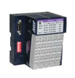
RSTi Industrial I/O
The Profibus and DeviceNet Network Interfaces are also available with built-in I/O to
reduce cost and footprint. The network interfaces can be expanded and support all of
the RSTi I/O types.
Network Interfaces with Built-in I/O
STXPBS332 STXPBS016 STXPBS116
Product Name Slave Network Interface with
32 Source Outputs Built-in
Slave Network Interface with
16 Relay Outputs
Slave Network Interface with
16 Isolated Relay Outputs
Lifecycle Status Active Target Release July 2012 Target Release July 2012
Module Type Slave Network Interface Slave Network Interface Slave Network Interface
Field Busses/Device Networks Profibus V1 Profibus V1 Profibus V1
Protocol Supported
Freeze mode, Sync mode,
Auto baudrate, Fail safe mode
Freeze mode, Sync mode,
Auto baudrate, Fail safe mode
Freeze mode, Sync mode,
Auto baudrate, Fail safe mode
Features
Profibus DP Network Slave has
built-in 32 Source Outputs
with expansion support
Profibus DP Network Slave has
built-in 16 Relay Outputs
with expansion support
Profibus DP Network Slave has
built-in 16 Isolated Relay Outputs
with expansion support
Baud Rate 9.6K to 12Mbps 9.6K to 12Mbps 9.6K to 12Mbps
I/O Data Size
Total: Inputs 36 bytes/Outputs 36 bytes total
(4 bytes In/ 4 bytes Out for base module
and 32 bytes In/32 bytes Out for expansion
modules); Discrete I/O: Maximum Discrete
I/O: 256 inputs/ 256 outputs; Analog I/O:
16 Channels In/ 16 Channels Out
Total: Inputs 32bytes/Outputs 32bytes;
Discrete I/O: 256 inputs/ 256 outputs;
Analog I/O: 16 Channels In/
16 Channels Out
Total: Inputs 36 bytes/Outputs 36 bytes total
(4 bytes In/ 4 bytes Out for base module
and 32 bytes In/32 bytes Out for expansion
modules); Discrete I/O: Maximum Discrete
I/O: 256 inputs/ 256 outputs; Analog I/O:
16 Channels In/ 16 Channels Out
LEDs Module Status, Network Status, I/O Status Module Status, Network Status, I/O Status Module Status, Network Status, I/O Status
Diagnostic Supported Yes Yes Yes
Maximum Bus Length 100 meters to 1.2Km depending on baud rate 100 meters to 1.2Km depending on baud rate 100 meters to 1.2Km depending on baud rate
Maximum Number of Nodes Supported 100 100 100
Number of Expansion I/O Supported 8 8 8
Number of Points 32 16 16
System Power Requirement 24 VDC (19.2 to 28.8 VDC) with Current
Limit, Reverse Polarity Protection
24 VDC (19.2 to 28.8 VDC) with Current
Limit, Reverse Polarity Protection
24 VDC (19.2 to 28.8 VDC) with Current
Limit, Reverse Polarity Protection
Field Power Requirement 24 VDC (11 VDC to 28.8 VDC) 24 VDC (11 VDC to 28.8 VDC) 24 VDC (11 VDC to 28.8 VDC)
Input Type
Input Voltage Range
Input Impedance
Input Signal Delay
Response Time (ms) < 0.3msec 10msec 10msec
Trigger Voltage
Points per Common 32 4 1
Output Type 32 Point 24 VDC Positive Logic 16 Point Relay 16 Isolated Relay
Output Range Nominal 24 VDC; 11 to 28.8 VDC 5 to 28.8 VDC, 48 VDC, 110 VDC, 250 VAC 5 to 28.8 VDC, 48 VDC, 110 VDC, 250 VAC
Protection Short protection, Over Temperature
Protection, Over Current Limit
Minimum Output Load 100 micro Amps, 100 millivolts VDC per point 100 micro Amps, 100 millivolts VDC per point
Load Current per Point
0.5 Amps per point 2 Amps at 5 to 28.8 VDC, 0.8 Amps at
48 VDC, 0.5 Amps at 110 VDC,
2 Amps at 250 VAC
2 Amps at 5 to 28.8 VDC, 0.8 Amps at
48 VDC, 0.5 Amps at 110 VDC,
2 Amps at 250 VAC
Output Inrush Current
Polarity Source
Configuration Tool GSM File GSM File GSM File
Interface Connector Type DB 9 connector (RS-485) DB 9 connector (RS-485) DB 9 connector (RS-485)
Power Dissipation 50 mA typical @ 24 VDC 50 mA typical @ 24 VDC 50 mA typical @ 24 VDC
Connector Type
Spring Clamp Terminal Block Spring Clamp Terminal Block Spring Clamp Terminal Block
Internal Power Used (5 VDC loading) 400 mA @ Maximum 5 VDC 400 mA @ Maximum 5 VDC 400 mA @ Maximum 5 VDC
Dimensions (H x W x D) in mm 99 x 83 x 70 99 x 83 x 70 99 x 83 x 70
Purchase history
| User name | Member Level | Quantity | Specification | Purchase Date |
|---|
Total 0 Record
Related products

Customer Reviews
Satisfaction :
5 Stars
No evaluation information


- other
- LTI Drives
- ADLINK
- Beckhoff
- Other Brands
- AMAT
- Iba
- PEPPERL+FUCHS
- Aerotech
- WATLOW
- MAN
- ADVANCED
- Abaco
- YOKOGAWA
- KOLLMORGEN
- MEGGITT
- kong-sberg
- METSO
- Motorola
- NI
- OEMAX
- RELIANCE
- scanlab
- schneider
- uniop
- Vibro-Meter
- Honeywell
- Rolls-Royce
- MOOG
- GE
- B&R
- Woodward
- Yaskawa
- xYCOM
- Siemens
- Emerson
- HIMA
- Bently
- ZYGO
- FOXBORO
- OMACO
- PROSOFT
- ENTERASYS
- TRICONEX
- Parker
- Lenze
- KEBA
- Alstom
- CTI
- ABB
- A-B
145

-
 ADLINK NuPRO-E72 PICMG 1.3 Full length Industrial SHB Single Board Computer
 -
 ADLINK MXE-5400 series fanless embedded industrial computer
 -
 ADLINK M-322 Industrial ATX Motherboard
 -
 ADLINK IMB-M43H Industrial ATX Motherboard
 -
 ADLINK IMB-M42H Industrial ATX Motherboard
 -
 ADLINK i915GV-INA ATX motherboard
 -
 ADLINK ETX-NR667 Embedded ETX Standard Computer Module
 -
 ADLINK ETX-BT (PATA to SATA version) User Manual
 -
 ADLINK CM1-BT1 PC/104 Single Board Computer
 -
![ADLINK cPCI-8217 [R] 3U CompactPCI VGA/LCD Display Module](https://aosspic10001.websiteonline.cn/hkw632bc8/image/image_aJXQRn.png) ADLINK cPCI-8217 [R] 3U CompactPCI VGA/LCD Display Module
ADLINK cPCI-8217 [R] 3U CompactPCI VGA/LCD Display Module -
 ADLINK AmITX-SL-G Mini ITX Embedded Motherboard
 -
 ADLINK AmITX-AL-I ultra-thin Mini ITX industrial motherboard
 -
 ADLINK NuPRO-E315 Full length PICMG 1.3 Industrial SHB Single Board Computer
 -
 ADLINK NuPRO-842 Full length PICMG 1.0 PCI/ISA Industrial Single Board Computer
 -
 ADLINK NuPRO-900A PICMG 1.2 ePCI-X Dual Xeon Industrial System Motherboard (SHB)
 -
 ADLINK cPCI-6910 series 6U CompactPCI single board computer
 -
 ADLINK cPCI-6860A 6U CompactPCI dual core single board computer with cPCI-R6860A rear adapter board
 -
 ADLINK cPCI-8168 6U CompactPCI Eight Axis Motion Control Card
 -
 ADLINK NuPRO-E340 PICMG 1.3 Industrial SHB motherboard
 -
 ADLINK NuPRO-A40H Full length PICMG1.0 Industrial Single Board Computer (SBC)
 -
 ADLINK NuPRO-852 Full length PICMG1.0 Industrial Single Board Computer
 -
 ADLINK NuPRO-841 Full length Industrial SBC
 -
 ADLINK NuPRO-590/591/592 series Socket7 full-length industrial SBC
 -
 ADLINK MXE-5500 series fanless embedded industrial computer
 -
 ADLINK MXE-200/200i Fanless Embedded Machine
 -
 ADLINK cPCI-6770 series CompactPCI CPU board
 -
 ADLINK NuPRO-A301 standard PICMG 1.0 full-length industrial SBC single board computer
 -
 ADLINK NuPRO-965 PICMG 1.3 SHB Express Full length Industrial Motherboard
 -
 ADLINK NuPRO-935A Full length PICMG1.0 Industrial Single Board Computer
 -
 ADLINK NuPRO-865 Full length Single Board Computer
 -
 ADLINK NuPRO-840 DV/LV Full Length PICMG Industrial Single Board Computer
 -
 ADLINK NuPRO-770 series full-length industrial single board computer
 -
 ADLINK NuPRO-595 series half length Socket 7 industrial motherboard
 -
 ADLINK cPCI-6840 series 6U CompactPCI single board computer
 -
 Foxboro 43AP series pneumatic indicator controller (PSS 3-1B3 A)
 -
 ADLINK cPCI-3720 Series 3U Low Power CompactPCI Single Board Computer
 -
 ADLINK NuPRO-E47, PICMG 1.3 full-length industrial SHB system motherboard
 -
 ADLINK NuPRO-E43 PICMG 1.3 full-length system motherboard
 -
 ADLINK NuPRO-780 series full-length industrial CPU board
 -
 ADLINK cPCI-6965 series 6U CPCI single board computer
 -
 ADLINK USB/LPCI/LPCIe-3488A GPIB interface card
 -
 Rittal SK 3241.700 Blue e+Fan Filter Unit
 -
 ADLINK cPCI-8168 6U CompactPCI 8-Axis Motion Control Card
 -
 ADLINK PCIe PXIe-8638 PCIe to PXIe Bus Expansion Kit
 -
 ADLINK PCIe GIE7x series acquisition card
 -
 ADLINK PCIe-7396 96 96 channel TTL digital IO card
 -
 ADLINK PCI/MPC/PXI-8164 Three in One Motion Control Card
 -
 ADLINK PCI-8154 Four Axis Pulse Motion Control Card
 -
 ADLINK PCI-8134 Four Axis Servo/Stepper Motion Control Card
 -
 ADLINK NuPRO-E42 PICMG1.3 full-length SHB motherboard
 -
 ADLINK MXC-6600 series high-performance fanless extended industrial computer
 -
 ADLINK MXC-6000 series embedded industrial control computer
 -
 ADLINK MXC-2300 series fanless expandable embedded industrial computer
 -
 ADLINK MCM-204 Independent Ethernet DAQ User Manual
 -
 ADLINK MCM-100/102 Edge IoT Platform for Machine Condition Monitoring User’s Manual
 -
 ADLINK MXC-6400 series sixth generation Core Fanless Scalable Industrial Control Computer
 -
 ADLINK Matrix Full Series Fanless Embedded Industrial Control Computers
 -
 ADLINK GIE64+4-channel PoE Gigabit Vision Capture Card
 -
 Honeywell UMS Security System Troubleshooting Guide
 -
 Honeywell Expert Series-C I/O Module
 -
 ADLINK EOS-1200 Embedded Vision Host
 -
 ADLINK DLAP-5200 series high-performance fanless AI industrial computer
 -
 ADLINK DLAP-4000 series embedded industrial control computer
 -
 ADLINK Matrix MXC-2000 Series Fanless Industrial Control Computer Specification
 -
 ADLINK DAQ -/DAQE -/PXI-2000 Series Multi functional Synchronous Acquisition Card
 -
 ADLINK cPCI-6520 6U CompactPCI Single Board Computer
 -
 ADLINK CM1-86DX3 PC/104 Single Board Computer
 -
 Honeywell DC1000 series PID temperature controller
 -
 ALSTOM MiCOM C264 Modular Substation Controller
 -
 EMERSON AMS 2140 Mechanical Health Analyzer
 -
 ADLINK NuPRO-E320 PICMG1.3 Full length Industrial Motherboard
 -
 ADLINK NuPRO-800 Series Full length Industrial SBC User Manual
 -
 ADLINK NuPRO-598 Industrial Single Board Computer
 -
 ADLINK MXC-6300 Fanless Embedded Industrial Control Computer
 -
 ADLINK Express-BASE7 User Manual
 -
 ADLINK DLAP-211 Series Fanless Edge AI Platform Specification Manual
 -
 ADLINK PCI/LPCI/LPCIe/cPCI-723X series 32 channel isolated digital I/O card
 -
 ADLINK cPCI-6965 series 6U CompactPCI single board computer
 -
 ADLINK NuDAQ 7200 series high-speed digital I/O board
 -
 Linghua ADLINK DLAP Deep Learning Acceleration Platform Product Manual
 -
 DEIF TCM-2 thyristor control module
 -
 Installation Manual for DEIF MVR-200 Series Medium Voltage Protection Device
 -
 DEIF MDR-2 multifunctional differential relay
 -
 DEIF AOM-1 Analog Output Module
 -
 DEIF AGI 400 series industrial/marine touch screen
 -
 Installation Manual for DEIF BRW-1 Marine Wing Bridge Instrument
 -
 DEIF AGC200 Quick Start Guide
 -
 DEIF AGC Multi line 2 Generator Set ControllerProduct basic information
 -
 ABB SPA-ZC 400 Ethernet Gateway Installation and Debugging Manual
 -
 ABB REM 543/545 motor generator protection device
 -
 DEIF PPU 300 controller
 -
 DEIF Delomatic 4 Offshore/Ocean Platform Dedicated Generator Power Management System DM-4
 -
 DEIF Delomatic Modular Generator Set Integrated System
 -
 DEIF AGC-4 Mk II Generator Set Controller
 -
 DEIF AGC-4 diesel generator set integrated controller
 -
 DEIF Multi line 2 Series PPU Unit Power Management (PPM) Operation Manual
 -
 DEIF Multi line 2 V2.4X Installation Manual
 -
 Beckwith M-6280 Digital Capacitor Bank Controller
 -
 Beckwith M-3311 Transformer Protection Relay
 -
 Beckwith M-3311A Transformer Integrated Protection Device
 -
 Beckwith M-3310 Transformer Integrated Protection Device Specification
 -
 Beckwith M-0359 Syncrocloser Check Plus Application Guide for Synchronous Calibration Relay
 -
 Beckwith M-0293A On Load Tap changer Controller Application Guide
 -
 DEIF GPU-3 Synchronous/Asynchronous Generator Integrated Microcomputer Protection Controller
 -
 Installation Instructions for DEIF PPM-3
 -
 Beckwith M-3520 distributed power grid connected comprehensive protection device
 -
 Beckwith M-3430 generator comprehensive protection device
 -
 Beckwith M-2293B adapter panel
 -
 Beckwith M-2001C digital on load voltage regulator controller
 -
 Beckwith M-2001B Digital On Load Voltage Regulating Controller
 -
 Beckwith M-0388/M-0389 synchronous verification relay
 -
 Beckwith M-0193B synchronous closing device
 -
 Beckwith M-0115A Transformer Parallel Balancing Module
 -
 Beckwith M-0067E on load tap changer controller
 -
 Beckwith M-4272 Digital Motor Bus Switching System
 -
 Beckwith M-3311A Transformer Integrated Protection Device
 -
 Beckwith M-3425A Generator Integrated Protection Device Manual
 -
 Basler BE1-27/BE1-59/BE1-27/59 undervoltage/overvoltage relay
 -
 Basler AVC63-12/AVC125-10 excitation voltage regulator
 -
 Basler L301kc Color Three Line Array Camera Operation Manual
 -
 Basler CBS 212A Current Enhanced Excitation System
 -
 Basler BE3-25 synchronous check relay
 -
 Operation Manual for Basler BE1-32R/BE1-32O/U Direction Power Relay
 -
 Basler Electric PRS-250 Veri Sync Synchronous Relay
 -
 Basler Pilot Series Area Array Industrial Camera piA2400-17gc
 -
 Basler BE1-11g comprehensive protection device for generator
 -
 Basler VR63-4C/UL Analog Excitation Voltage Regulator
 -
 Basler BE1-DFPR distribution feeder protection relay

K-JIANG

Add: Jimei North Road, Jimei District, Xiamen, Fujian, China
Tell:+86-15305925923