
K-WANG
+086-15305925923
Service expert in industrial control field!


Product
Article
NameDescriptionContent
Adequate Inventory, Timely Service
pursuit of excellence


Ship control system
Equipment control system
Power monitoring system
Brand
Product parameters
- Telephone:+86-15305925923
- contacts:Mr.Wang
- Email:wang@kongjiangauto.com
Description
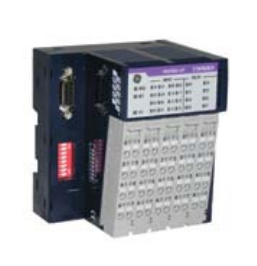
The Profibus and DeviceNet Network Interfaces are also available with built-in I/O to
reduce cost and footprint. The network interfaces can be expanded and support all of
the RSTi I/O types.
GE STXPBS924 Network Interfaces with Built-in I/O
RSTi Industrial I/O
The Profibus and DeviceNet Network Interfaces are also available with built-in I/O to
reduce cost and footprint. The network interfaces can be expanded and support all of
the RSTi I/O types.
Network Interfaces with Built-in I/O
STXPBS924 STXPBS825 STXPBS925
Product Name Slave Network Interface with 16 Negative
Logic Inputs and 16 Relay Outputs
Slave Network Interface with 16 Positive
Logic Inputs and 16 Isolated Relay Outputs
Slave Network Interface with 16 Negative
Logic Inputs and 16 Isolated Relay Outputs
Lifecycle Status Target Release July 2012 Target Release July 2012 Target Release July 2012
Module Type Slave Network Interface Slave Network Interface Slave Network Interface
Field Busses/Device Networks Profibus V1 Profibus V1 Profibus V1
Protocol Supported
Freeze mode, Sync mode,
Auto baudrate, Fail safe mode
Freeze mode, Sync mode,
Auto baudrate, Fail safe mode
Freeze mode, Sync mode,
Auto baudrate, Fail safe mode
Features
Baud Rate 9.6K to 12Mbps 9.6K to 12Mbps 9.6K to 12Mbps
I/O Data Size
Total: Inputs 36 bytes/Outputs 36 bytes total
(4 bytes In/ 4 bytes Out for base module
and 32 bytes In/32 bytes Out for expansion
modules); Discrete I/O: Maximum Discrete
I/O: 256 inputs/ 256 outputs; Analog I/O:
16 Channels In/ 16 Channels Out
Total: Inputs 36 bytes/Outputs 36 bytes total
(4 bytes In/ 4 bytes Out for base module
and 32 bytes In/32 bytes Out for expansion
modules); Discrete I/O: Maximum Discrete
I/O: 256 inputs/ 256 outputs; Analog I/O:
16 Channels In/ 16 Channels Out
Total: Inputs 36 bytes/Outputs 36 bytes total
(4 bytes In/ 4 bytes Out for base module
and 32 bytes In/32 bytes Out for expansion
modules); Discrete I/O: Maximum Discrete
I/O: 256 inputs/ 256 outputs; Analog I/O:
16 Channels In/ 16 Channels Out
LEDs Module Status, Network Status, I/O Status Module Status, Network Status, I/O Status Module Status, Network Status, I/O Status
Diagnostic Supported Yes Yes Yes
Maximum Bus Length 100 meters to 1.2Km depending on baud rate 100 meters to 1.2Km depending on baud rate 100 meters to 1.2Km depending on baud rate
Maximum Number of Nodes Supported 100 100 100
Number of Expansion I/O Supported 8 8 8
Number of Points 16 In/16 Out 16 In/16 Out 16 In/16 Out
System Power Requirement 24 VDC (19.2 to 28.8 VDC) with Current
Limit, Reverse Polarity Protection
24 VDC (19.2 to 28.8 VDC) with Current
Limit, Reverse Polarity Protection
24 VDC (19.2 to 28.8 VDC) with Current
Limit, Reverse Polarity Protection
Field Power Requirement 24 VDC (11 VDC to 28.8 VDC) 24 VDC (11 VDC to 28.8 VDC) 24 VDC (11 VDC to 28.8 VDC)
Input Type 16 Point 24 VDC Negative Logic 16 Point 24 VDC Positive Logic 16 Point 24 VDC Negative Logic
Input Voltage Range 24 VDC (11 VDC to 28.8 VDC) 24 VDC (11 VDC to 28.8 VDC) 24 VDC (11 VDC to 28.8 VDC)
Input Impedance ~5.4K ohms ~5.4K ohms ~5.4K ohms
Input Signal Delay < 0.5msec < 0.5msec < 0.5msec
Response Time (ms) 10msec 10msec 10msec
Trigger Voltage ON State: 9 VDC, OFF State: 5 VDC ON State: 9 VDC, OFF State: 5 VDC ON State: 9 VDC, OFF State: 5 VDC
Points per Common 16 for Inputs and 1 for Outputs 16 for Inputs and 1 for Outputs 16 for Inputs and 1 for Outputs
Output Type 16 Point Relay 16 Point Isolated Relay 16 Point Isolated Relay
Output Range 5 to 28.8 VDC, 48 VDC, 110 VDC, 250 VAC 5 to 28.8 VDC, 48 VDC, 110 VDC, 250 VAC 5 to 28.8 VDC, 48 VDC, 110 VDC, 250 VAC
Protection
Minimum Output Load 100 micro Amps, 100 millivolts VDC per point 100 micro Amps, 100 millivolts VDC per point 100 micro Amps, 100 millivolts VDC per point
Load Current per Point
2 Amps at 5 to 28.8 VDC, 0.8 Amps at 48 VDC,
0.5 Amps at 110 VDC, 2 Amps at 250 VAC
2 Amps at 5 to 28.8 VDC, 0.8 Amps at 48 VDC,
0.5 Amps at 110 VDC, 2 Amps at 250 VAC
2 Amps at 5 to 28.8 VDC, 0.8 Amps at 48 VDC,
0.5 Amps at 110 VDC, 2 Amps at 250 VAC
Output Inrush Current
Polarity
Configuration Tool GSM File GSM File GSM File
Interface Connector Type DB 9 connector (RS-485) DB 9 connector (RS-485) DB 9 connector (RS-485)
Power Dissipation 50 mA typical @ 24 VDC 50 mA typical @ 24 VDC 50 mA typical @ 24 VDC
Connector Type
Spring Clamp Terminal Block Spring Clamp Terminal Block Spring Clamp Terminal Block
Internal Power Used (5 VDC loading) 400 mA @ Maximum 5 VDC 400 mA @ Maximum 5 VDC 400 mA @ Maximum 5 VDC
Dimensions (H x W x D) in mm 99 x 83 x 70 99 x 83 x 70 99 x 83 x 70
Industrial I/O
STXDNS032 STXDNS132 STXDNC032
Product Name Slave Network Interface with
32 Positive Logic Inputs Built-in
Slave Network Interface with
32 Negative Logic Inputs Built-in
Slave Network Interface with
32 Positive Logic Inputs Built-in
Lifecycle Status Target Release April 2012 Target Release April 2012 Target Release April 2012
Module Type Slave Network Interface Slave Network Interface Slave Network Interface
Field Busses/Device Networks DeviceNet DeviceNet DeviceNet
Protocol Supported
I/O Slave Message (Group 2 only slave),
Poll command. Bit_strobe command,
Cyclic command, COS command
I/O Slave Message (Group 2 only slave),
Poll command. Bit_strobe command,
Cyclic command, COS command
I/O Slave Message (Group 2 only slave),
Poll command. Bit_strobe command,
Cyclic command, COS command”
Features
Baud Rate 125K bits/s, 250Kbps, 500Kbps
(Auto baud rate selection)
125K bits/s, 250Kbps, 500Kbps
(Auto baud rate selection)
125K bits/s, 250Kbps, 500Kbps
(Auto baud rate selection)
I/O Data Size
Total: Inputs 36 bytes/Outputs 34 bytes total
(4 bytes In/ 4 bytes Out for base
module and 32 bytes In/30 bytes Out
for expansion modules)
Total: Inputs 36 bytes/Outputs 34 bytes total
(4 bytes In/ 4 bytes Out for base
module and 32 bytes In/30 bytes Out
for expansion modules)
Total: Inputs 4 bytes/Outputs 4 bytes
LEDs Module Status, Network Status, I/O Status Module Status, Network Status, I/O Status Module Status, Network Status, I/O Status
Diagnostic Supported Yes Yes Yes
Maximum Bus Length Up to 500 meters depending on baud rate Up to 500 meters depending on baud rate Up to 500 meters depending on baud rate
Maximum Number of Nodes Supported 64 64 64
Number of Expansion I/O Supported 10 10 None Supported
Number of Points 32 In 32 In 32
System Power Requirement 24 VDC (19.2 to 28.8 VDC) with Current Limit,
Reverse Polarity Protection
24 VDC (19.2 to 28.8 VDC) with Current Limit,
Reverse Polarity Protection
24 VDC (11 VDC to 28.8 VDC) with Current
Limit, Reverse Polarity Protection
Field Power Requirement 24 VDC (11 VDC to 28.8 VDC) 24 VDC (11 VDC to 28.8 VDC) 24 VDC (11 VDC to 28.8 VDC)
Input Type 32 Point 24 VDC Positive Logic 32 Point 24 VDC Negative Logic 32 Point 24 VDC Positive Logic
Input Voltage Range 24 VDC (11 VDC to 28.8 VDC) 24 VDC (11 VDC to 28.8 VDC) 24 VDC (11 VDC to 28.8 VDC)
Input Impedance ~5.4K ohms ~5.4K ohms ~5.4K ohms
Input Signal Delay < 0.5msec < 0.5msec < 0.5msec
Response Time (ms)
Trigger Voltage ON State: 9 VDC, OFF State: 5 VDC ON State: 9 VDC, OFF State: 5 VDC ON State: 9 VDC, OFF State: 5VD
Points per Common 16 for Inputs and 1 for Outputs 16 for Inputs and 1 for Outputs 16
Output Type
Output Range
Protection
Minimum Output Load
Load Current per Point
Output Inrush Current
Polarity
Configuration Tool EDS File EDS File EDS File
Interface Connector Type 5 pin connector 5 pin connector 5 pin connector
Power Dissipation 110 mA typical 110 mA typical 80 mA typical
Connector Type
Spring Clamp Terminal Block Spring Clamp Terminal Block Connector Type
Internal Power Used (5 VDC loading) 600 mA @ Maximum 5 VDC 600 mA @ Maximum 5 VDC Not Applicable
Dimensions (H x W x D) in mm 99 x 83 x 70 99 x 83 x 70 80 x 35 x 55
The Profibus and DeviceNet Network Interfaces are also available with built-in I/O to
reduce cost and footprint. The network interfaces can be expanded and support all of
the RSTi I/O types.
Purchase history
| User name | Member Level | Quantity | Specification | Purchase Date |
|---|
Total 0 Record
Related products

Customer Reviews
Satisfaction :
5 Stars
No evaluation information


- other
- ADLINK
- LTI Drives
- Other Brands
- AMAT
- Iba
- PEPPERL+FUCHS
- Aerotech
- WATLOW
- MAN
- ADVANCED
- Abaco
- YOKOGAWA
- KOLLMORGEN
- MEGGITT
- kong-sberg
- METSO
- Motorola
- NI
- OEMAX
- RELIANCE
- scanlab
- schneider
- uniop
- Vibro-Meter
- Honeywell
- Rolls-Royce
- MOOG
- GE
- B&R
- Woodward
- Yaskawa
- xYCOM
- Siemens
- Emerson
- HIMA
- Bently
- ZYGO
- FOXBORO
- OMACO
- PROSOFT
- ENTERASYS
- TRICONEX
- Parker
- Lenze
- KEBA
- Alstom
- CTI
- ABB
- A-B
145

-
 Beckwith M-3310 Transformer Integrated Protection Device Specification
 -
 Beckwith M-0359 Syncrocloser Check Plus Application Guide for Synchronous Calibration Relay
 -
 Beckwith M-0293A On Load Tap changer Controller Application Guide
 -
 DEIF GPU-3 Synchronous/Asynchronous Generator Integrated Microcomputer Protection Controller
 -
 Installation Instructions for DEIF PPM-3
 -
 Beckwith M-3520 distributed power grid connected comprehensive protection device
 -
 Beckwith M-3430 generator comprehensive protection device
 -
 Beckwith M-2293B adapter panel
 -
 Beckwith M-2001C digital on load voltage regulator controller
 -
 Beckwith M-2001B Digital On Load Voltage Regulating Controller
 -
 Beckwith M-0388/M-0389 synchronous verification relay
 -
 Beckwith M-0193B synchronous closing device
 -
 Beckwith M-0115A Transformer Parallel Balancing Module
 -
 Beckwith M-0067E on load tap changer controller
 -
 Beckwith M-4272 Digital Motor Bus Switching System
 -
 Beckwith M-3311A Transformer Integrated Protection Device
 -
 Beckwith M-3425A Generator Integrated Protection Device Manual
 -
 Basler BE1-27/BE1-59/BE1-27/59 undervoltage/overvoltage relay
 -
 Basler AVC63-12/AVC125-10 excitation voltage regulator
 -
 Basler L301kc Color Three Line Array Camera Operation Manual
 -
 Basler CBS 212A Current Enhanced Excitation System
 -
 Basler BE3-25 synchronous check relay
 -
 Operation Manual for Basler BE1-32R/BE1-32O/U Direction Power Relay
 -
 Basler Electric PRS-250 Veri Sync Synchronous Relay
 -
 Basler Pilot Series Area Array Industrial Camera piA2400-17gc
 -
 Basler BE1-11g comprehensive protection device for generator
 -
 Basler VR63-4C/UL Analog Excitation Voltage Regulator
 -
 Basler BE1-DFPR distribution feeder protection relay
 -
 Basler CBS310/CBS320 current strong excitation system
 -
 Basler UFOV250A/UFOV260A Low Frequency Overvoltage Module
 -
 Basler MVC104/MVC108/MVC232 manual voltage control device
 -
 Basler XR2002/XR2002F PMG excitation regulator
 -
 Basler DECS-400 Digital Excitation Control System
 -
 Basler DGC-2020 Digital Generator Set Controller
 -
 Basler MVC-300 Electronic Manual Excitation Controller
 -
 Basler MVC-104/MVC-108/MVC-232 manual excitation controller
 -
 Basler SSR32-12/SSR63-12/SSR125-12 Static Excitation Voltage Regulator
 -
 Basler SR4A/SR8A Analog Excitation Voltage Regulator
 -
 Basler BE2000E Digital Excitation Voltage Regulator
 -
 Basler DECS-2100 Digital Excitation System
 -
 Basler BE1-851 Overcurrent Protection Device Manual
 -
 Basler APR 63-5 Voltage Regulator
 -
 Basler BE1-FLEX Integrated Protection Control System
 -
 Basler BE1-700V digital voltage protection relay
 -
 Basler BE1-87B high impedance bus differential relay
 -
 Basler BE1-40Q demagnetization relay
 -
 Basler BE1-60 Voltage Balance Relay
 -
 Basler BE1-47N negative sequence voltage phase sequence relay
 -
 Basler BE1-81O/U digital frequency relay
 -
 Basler BE1-11f Feedline Integrated Protection Device Manual
 -
 Basler DECS-250 Digital Excitation Control System
 -
 Basler DECS-100 Digital Excitation Control System
 -
 Basler BE1-BPR Circuit Breaker Protection Relay
 -
 Basler BE1-50/51B-255 overcurrent relay
 -
 Basler BE1-25 synchronous check relay
 -
 Basler BE1-51 microcomputer time limited overcurrent relay
 -
 Basler DECS-300 Digital Excitation Control System
 -
 Mitsubishi MELSEC-F FX series programmable controllers
 -
 Hirschmann cSCALE Mobile Machinery Modular Controller
 -
 Hirschmann OZD Profi G12DU/G12DK/G12DE ATEX1 PROFIBUS Fiber Optic Repeater Manual
 -
 Hirschmann OCTOPUS OS20/OS24 Network Managed IP65/IP67 Industrial Switch Installation Manual
 -
 Hirschmann RS20/RS22/RS30/RS32/RS40 Series Industrial Rail Switch Installation Manual
 -
 Hirschmann EAGLE One Industrial Ethernet Firewall Installation Manual
 -
 Hirschmann MACH102 Series Industrial Switch Installation Manual
 -
 Hirschmann MS20/MS30 Modular Industrial Switch Installation Manual
 -
 Hirschmann BRS20/22/30/32/40/42/50/52 Series BOBCAT Industrial Rail Switch Installation Manual
 -
 Hirschmann RSB20 Basic Series Industrial Rail Switch Installation Manual
 -
 Hirschmann RS20 Basic Series Industrial Ethernet DIN-Rail Switches
 -
 BECKHOFF EP20xx/EP28xx IP67 EtherCAT Box Digital Output Module
 -
 BECKHOFF EL5102 Incremental Encoder Terminal Manual
 -
 BECKHOFF CU8803-000x CP Link4 Launch Box Operation Manual
 -
 Beckhoff CU20xx/CU22xx Industrial Unmanned Switch Manual
 -
 BECKHOFF AMP8000 Distributed Servo System Operation Manual
 -
 BECKHOFF EL2911/EL2911-2200 TwinSAFE Safety Potential Supply Terminal Manual
 -
 BECKHOFF EL600x/EL602x series EtherCAT serial port terminal module
 -
 BECKHOFF CP6700-0001-0050/0060 Integrated Machine Manual
 -
 BECKHOFF CP70xx Series Control Panel Installation and Operation Manual
 -
 BECKHOFF CP29xx Cabinet Mounted Industrial Touch Panel Official Operation Manual
 -
 Beckhoff C6650-0060 Control Cabinet Industrial PC
 -
 Beckhoff BK series K-bus to EtherCAT coupler
 -
 Beckhoff CX20x0 Series Embedded Industrial Control Computer Manual
 -
 Beckhoff CP77xx Series Industrial Panel PC Installation and Operation Manual
 -
 Beckhoff EL41xx Series 16 Bit Analog Output Terminal Manual
 -
 Beckhoff C63xx-0020 series control cabinet industrial PC
 -
 Beckhoff C6920-0060 Control Cabinet Industrial PC
 -
 Beckhoff CU8800-0010 USB transmitter extender (TX)
 -
 Beckhoff AX2000 series digital servo amplifier
 -
 Beckhoff AX8000 Modular Multi Axis Servo System
 -
 Beckhoff CP27xx Embedded Panel PC User Manual
 -
 Beckhoff CP69xx Industrial Embedded Control Panel
 -
 Beckhoff CP60xx Embedded Industrial Control Panel
 -
 Beckhoff CP72xx series panel PC official installation, operation, configuration, maintenance, and troubleshooting
 -
 Installation and Operation of Beckhoff CP78xx Series Control Panel
 -
 Beckhoff CP39xx series industrial touch control panel
 -
 Beckhoff CX8110 Embedded Industrial PC
 -
 Beckhoff CX50x0 series DIN rail embedded industrial PC
 -
 Beckhoff CP62xx series embedded panel PC
 -
 BECKHOFF C6030 Compact Industrial PC
 -
 UniOP ePAD32B/ePAD33B/ePAD33BT Industrial HMI
 -
 UniOP ePAD05&ePAD06 Industrial HMI
 -
 UniOP ePAD03/ePAD04 entry-level HMI
 -
 UniOP CP01R-04 Compact Industrial HMI
 -
UniOP BKDR-16 Industrial Human Machine Interface
-
 Beckwith M-3425A Generator Integrated Protection Relay
 -
 Basler DECS-200 Digital Excitation Control System
 -
 Basler DECS-250 Digital Excitation Control System Manual
 -
 HA-800 series AC servo drive
 -
 JUMO dTRANS p35 Pressure Sensor Operation Manual with IO Link Interface
 -
 KEBA XE 020 RFID Module
 -
 Honeywell SmartLine series transmitters
 -
 Eaton CROUSE-HINDS MTL MA30 RF and Surge Protector Operation Manual
 -
 Beckhoff EL31xx Series 16 Bit EtherCAT Analog Input Terminal Manual
 -
 BECKHOFF AX5000 series EtherCAT servo drive
 -
 BECKHOFF EL30xx Series 12 Bit Analog Input Terminal Manual
 -
 Beckhoff EL70x7 series stepper motor EtherCAT terminal manual
 -
 BECKHOFF CX52x0 Series Embedded Industrial PC Hardware Manual
 -
 BECKHOFF CX9000/CX9010 series embedded controllers
 -
 BECKHOFF AM8000/AM8500 Series Synchronous Servo Motor Operation Manual
 -
 BECKHOFF EL9xxx series EtherCAT system terminal
 -
 BECKHOFF EK110x/EK15xx series EtherCAT bus coupler
 -
 BECKHOFF CX51x0 Series Embedded PC Hardware Manual
 -
 BECKHOFF CX2100-0014 Embedded Power Unit User Manual
 -
 BECKHOFF CX1000 Series Modular Embedded Industrial PC Hardware Manual
 -
 BECKHOFF CP69xx series embedded industrial control panel usage instructions
 -
 Beckhoff C6030-0080 ultra compact industrial PC
 -
 IFM O3D series time-of-flight 3D industrial sensor usage instructions
 -
 Allen Bradley Guardmaster 440R series safety relay
 -
 OMRON SYSMAC CS1 Rack mounted Large and Medium sized PLC Selection

K-JIANG

Add: Jimei North Road, Jimei District, Xiamen, Fujian, China
Tell:+86-15305925923