
K-WANG
+086-15305925923
Service expert in industrial control field!
Product
Article
NameDescriptionContent
Adequate Inventory, Timely Service
pursuit of excellence


Ship control system
Equipment control system
Power monitoring system
Current position:
Brand
Product parameters
- Telephone:+86-15305925923
- contacts:Mr.Wang
- Email:wang@kongjiangauto.com
Description
Read and understand all of the following information regarding RIUP before attempting to remove and/or
replace any I/O module, particularly in a system that is actively controlling a process.
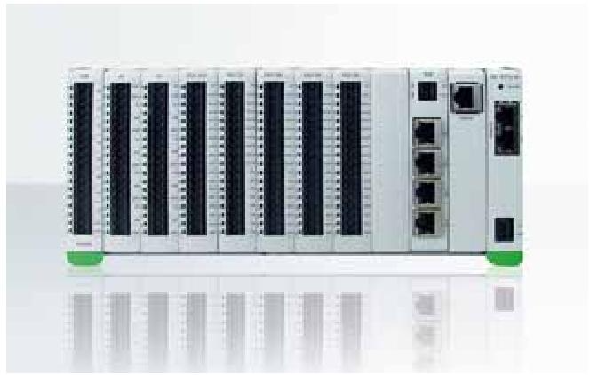
In legacy systems, all of the I/O Module types in the HC900 Controller System include the Removal and
Insertion Under Power (RIUP) feature. That is, while the rack is powered, any of the I/O Modules can be
removed or inserted
Honeywell High Voltage RTP Cable (2.5M, 8.2ft.) Note 6 (NOT FOR SIL2 SYSTEMS) 900RTC-H125
Removal and Insertion Under Power (RIUP)Read and understand all of the following information regarding RIUP before attempting to remove and/or
replace any I/O module, particularly in a system that is actively controlling a process.
In legacy systems, all of the I/O Module types in the HC900 Controller System include the Removal and
Insertion Under Power (RIUP) feature. That is, while the rack is powered, any of the I/O Modules can be
removed or inserted:
With no physical damage to the module, to the rack, or to other modules in the rack
Without disturbing the functions of other I/O modules in the rack or in the system.
Under carefully controlled circumstances, this feature enables the user to remove and insert an I/O module
without completely shutting down a running system. However, it must be recognized that removing or
inserting an I/O module under power is potentially hazardous to property and to personnel.
In new systems, the CPU and Scanner modules support RIUP.Circumstances that dictate prudent actions
depend on conditions and specific process applications at each user facility. It is the responsibility of site
personnel to know all potential consequences of RIUP, and to take actions to prevent all adverse
consequences before removing or inserting an I/O module under power. Table 13 provides some general
guidelines for establishing appropriate procedures at a given installation.
Table 13 – RIUP: Potential Hazards and Recommended Actions
Hazard Source Preventive Action(s)
Hazardous Voltages
Potentially lethal voltages on
Terminal Boards associated with
I/O Modules.
Disconnect all signals at terminal
blocks from sources of power before
removing the terminal block from
the I/O module.
Loss of control or view of
a running process
Each signal at each of the
terminals for an I/O module has a
specific function. Any or all of the
signals may be vital for safely
controlling a process.
Either:
Using trained personnel and
appropriate control mechanisms,
transfer to manual control for each
signal that is necessary to maintain
safe process control.
Or:
Bring the process to a safe stop
before initiating the removal or
insertion procedure.
EXPLOSION HAZARD Class 1, Division 2 Installations
DO NOT DISCONNECT EQUIPMENT UNLESS POWER HAS BEEN SWITCHED
OFF OR THE AREA IS KNOWN TO BE NON-HAZARDOUS.
I/O Module Installation Procedures
Table 14 – Connect Input/Output Wiring
Step Procedure Comments Reference
1 Using Rack #, Slot #,
Channel # data from a
Designer Software report,
fill in the tag names on the
Label for each configured
I/O Module. Module slot
position should take heat
de-rating into account.
See Heat Rise De-rating
page 52.
Be sure to use the
appropriate label for each
module type.
2 Place the appropriate label
supplied with the module
(tagname side out) into the
hinged door for each I/O
Module.
Slotted tabs, molded into
the door at top and
bottom, hold the label in
place.
Step Procedure Comments Reference
3 (Optional): Install jumper
combs into designated
Barrier style Terminal
Blocks, to reduce the
wiring required to supply
power:
Two-position jumper for
the DC Input Module
and/or on the DC Output
Module.
Ten-position jumper for
the AC Output Module.
Five-position jumper (10-
position jumper cut in half)
for a Relay Output
Module.
Refer to terminal block wiring diagrams for specific information.
4 For each configured and
labeled I/O Module, break
off the "key-tabs" in the
pattern that identifies each
module type.
(For a diagram of each
key-tab pattern, use the
I/O Modules and/or the
diagram shown next page.
Purchase history
| User name | Member Level | Quantity | Specification | Purchase Date |
|---|
Total 0 Record
Related products
Customer Reviews
Satisfaction :
5 Stars
No evaluation information


KONG JIANG


Add: Jimei North Road, Jimei District, Xiamen, Fujian, China
Tell:+86-15305925923


