
K-WANG
+086-15305925923
Service expert in industrial control field!


Product
Article
NameDescriptionContent
Adequate Inventory, Timely Service
pursuit of excellence


Ship control system
Equipment control system
Power monitoring system
Brand
Product parameters
- Telephone:+86-15305925923
- contacts:Mr.Wang
- Email:wang@kongjiangauto.com
Description
Integrated machine terminals for the pro tection, control, measurement and supervi
sion of small and medium size generators,
synchronous motors and large asynchro nous motors.
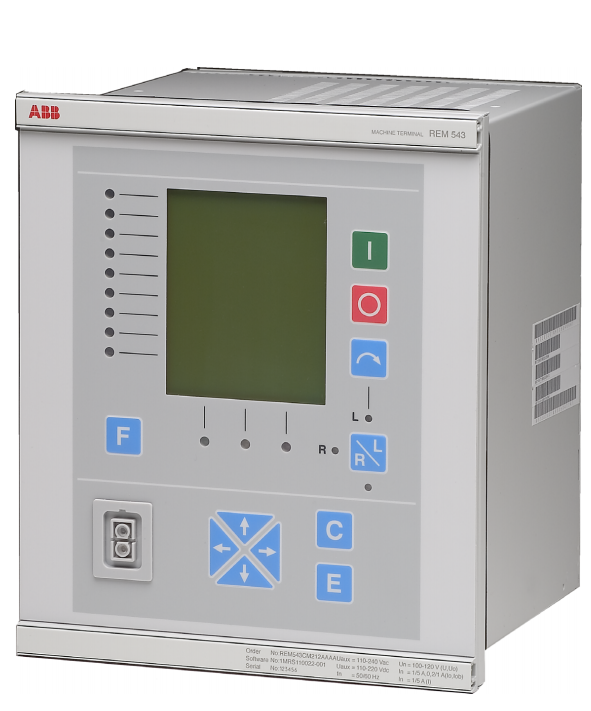
ABB REM543 Machine Terminals
Integrated machine terminals for the pro tection, control, measurement and supervi sion of small and medium size generators,
synchronous motors and large asynchro nous motors.
• Voltage and current measurement via con ventional measuring transformers or cur rent sensors and voltage dividers.
• Fixed man-machine interface including a
large graphic display, or an external display
module for flexible swichgear installation.
• Extended functionality including protec tion, control, measurement, condition moni toring and communication.
• Non-directional/directional overcur rent/earth-fault protection functions, over-
/undervoltage protection functions and spe cial functions for the protection of motors
and generators, e.g. voltage controlled
overcurrent protection, differential protec tion with several principles, underexcitation
protection, underimpedance protection
(line back-up prot.), thermal overload pro tection, protection against unbalanced
load, abnormal frequency protection,
reverse or low-forward power protection
and start-up supervision for motors.
• Control functions including local and
remote control of switching objects with
synchro-check, status indication of the
switching objects and interlockings on bay
and station level.
• Measurement of phase currents, phase-to phase and phase-to-neutral voltages, neu tral current and residual voltage, frequency,
power factor, active and reactive power
and energy.
• Optional RTD/mA I/O-module for stator
winding, bearing and ambient temperature
monitoring. Analog mA outputs for interfac ing with process control system.
• Condition monitoring including circuit breaker condition monitoring, trip circuit
supervision and internal self-supervision of
the machine terminal.
• Communication over three communication
interfaces: one for local communication
with a PC and the others for remote com munication with a substation control sys tem or with a substation monitoring system.
• Part of the ABB’s Distribution Automation
system.
Application The REM 543 and REM 545 rotating ma chine terminals are designed to be used as an
integrated main protection system of genera tor and generator-transformer units in small
and medium-power diesel, hydroelectric and
steam power plants, etc. The protection of
large and/or important MV synchronous and
asynchronous motors used e.g. in pumps,
fans, mills and crushers during start-up and
normal run forms another application area.
The REM 54_ machine terminals as inte grated packages make possible compact
marine environment solutions for unit protec tion, too.
In addition to protection, measurement, con trol and condition monitoring and general
functions, the machine terminals are provided
with a large amount of PLC functions allow ing several automation and sequence logic
functions needed for substation automation to
be integrated into one unit. The data commu nication properties include SPA bus, LON
bus or MODBUS communication with
higher-level equipment. Further, LON inter bay communication, together with PLC func tions, minimizes the need for hardwiring
between the machine terminals.
The machine terminals REM 543 and REM
545 differ from each other in the number of
digital inputs and outputs available. Please
refer to the section “Ordering” for more
details.
The REM 54_ machine terminals incorporate
a wide range of functions:
• Protection functions
• Measurement functions
• Control functions
• Condition monitoring functions
• General functions
• Communication functions
• Standard functions
The function blocks are documented on the
CD-ROM “Technical Descriptions of Func tions” (1MRS 750889-MCD).
Protection functions
Protection is one of the most important func tions of the REM 54_ machine terminal. The
protection function blocks are independent of
each other and have their own setting groups,
data recording, etc.
Typical current-based protection functions
(e.g. overcurrent) can use either Rogowski
coil or conventional current transformer mea surement. Correspondingly, voltage-based
functions (e.g. overvoltage) use either voltage
dividers or voltage transformers.
For further information about functionality
levels and the protection functions included
in them, refer to the table “Functionality lev els, protection functions” in section “Order ing”.
Measurement functions
The measurement functions include three phase currents, neutral current, three-phase
voltages, residual voltage, frequency, active
and reactive power and power factor.
An optional RTD/analogue module can be
used for measuring stator winding, bearing,
and ambient temperatures.
Disturbance recorder
The transient disturbance recorder is able to
record 16 current or voltage waveforms and
16 logic digital signals. The sampling fre quency of the analogue inputs is 2 kHz at the
rated frequency of 50 Hz and 2.4 kHz at the
rated frequency of 60 Hz.
The user can set the length of a recording
within a range determined by the number of
analogue inputs used. The number of record ings depends on the sampling frequency,
length of recordings and number of analogue
inputs.
The recordings can be uploaded with a DR Collector Tool which converts the data to a
COMTRADE format. The DR-Collector Tool
is supported in CAP501 and CAP505 relay
tools.
Control functions
The control functions are used to indicate the
status of switching devices, i.e. circuit break ers and disconnectors, and to execute open
and close commands for controllable switch ing devices of the switchgear. Furthermore,
control functions provide on/off switching
objects for control logic purposes and miscel laneous objects for data monitoring, etc.
The control functions configured with the
Relay Configuration Tool must be linked to
object status indicators included in the
MIMIC configuration picture displayed on
the HMI. The object status indicators are used
to indicate the status of switching devices via
the MIMIC picture and to control them
locally.
Condition monitoring functions
Condition monitoring function blocks such as
supervision of the energizing current and
voltage input circuit, operation time counter,
circuit-breaker electric wear, scheduled main tenance, trip circuit supervision and breaker
travel time are available for the REM 54_
machine terminals.
General functions
Additional functions are available for differ ent general purposes to be used in logics such
as activation of HMI backlight, switchgroups,
and resetting of operation indications, latched
output signals, registers and disturbance
recorder.
Communication functions
The machine terminal REM 54_ provides
three serial communication protocols: SPA,
LON and MODBUS.
Standard functions
Standard functions are used for logics such as
interlocking, alarming and control sequenc ing. The use of logic functions is not limited
and the functions can be interconnected with
protection, control, measurement, condition
monitoring and other standard functions. In
addition, digital inputs and outputs and LON
inputs and outputs can be connected to stan dard functions by using the Relay Configura tion Tool.
Other functions
Low auxiliary voltage indication
The REM 54_ terminal is provided with a
low auxiliary voltage indication feature. The
power supply module issues an internal alarm
signal when a drop in the power supply volt age is detected (ACFail, active low). The
alarm signal is activated if the power supply
voltage is about 10% below the lowest rated
DC input voltage of the power supply mod ule.
The indication of a low auxiliary voltage is
available in the machine terminal configura tion and can be connected to any signal out put of the REM54_.
Overtemperature indication
The REM 54_ machine terminal includes an
internal temperature supervision function.
The power supply module issues an internal
alarm signal when overtemperature has been
detected inside the terminal enclosure. The
alarm signal will be activated once the tem perature inside the terminal enclosure
increases to +78°C (+75°C…+83°C). Over temperature indication is available in the
machine terminal configuration and can be
connected to any signal output of the termi nal.
Analogue channels
The machine terminal measures the analogue
signals needed for protection, measuring, etc.
via sensors developed by ABB or galvani cally separated matching transformers.
Depending on whether sensors are included
or not, REM 54_ machine terminals have 9
(without sensors) or 10 (with sensors) physi cal analogue channels. The number of chan nels used depends on the machine terminal
configuration and the kind of matching trans formers or sensor inputs used. Furthermore,
the machine terminal includes virtual ana logue channels for calculating the neutral cur rent and residual voltage from phase currents
and voltages.
A current sensor (Rogowski coil) or a voltage
divider can be connected to each sensor input.
Analogue channels of the machine terminal
are configured with the CAP 505 Relay Prod uct Engineering Tool.
A separate scaling factor can be set for each
analogue channel. The factors enable differ ences between the ratings of the protected
unit and those of the measuring device (CTs,
VTs etc.). The setting value 1.00 means that
the rated value of the protected unit is exactly
the same as that of the measuring device.
• Machine terminals with the hardware
number
REM54x_xxxAAAA/CAAA/AAAB are
configured for matching transformers
• Machine terminals with the hardware
number REM54x_xxx
AABA/CABA/AABB are configured for
matching transformers and sensor inputs
Calculated analogue channels
The REM 54_ machine terminal includes vir tual channels to obtain the neutral current and
residual voltage when sensors are used. Cur rent sensors and voltage dividers are con nected to the machine terminal via coaxial
cables and therefore a residual connection of
the phase currents or an open-delta connec tion of the phase voltages cannot be made.
Both the amplitude and the phase angle are
calculated for the virtual channels.
Though primarily meant to be used with sen sors, the calculated analogue channels can
also be used with conventional current and
voltage transformers.
Note! When sensitive earth-fault protection is
needed, core balance transformers are not
recommended to be replaced with the numer ically derived sum of phase currents. Nor mally, an earth-fault setting below 10% of the
rated value requires the use of a core balance
transformer.
Digital inputs
The digital inputs of the machine terminal are
voltage-controlled and optically isolated. The
function of a digital input can be inverted.
The programmable filter time removes
debounces and short disturbances on a digital
input. The filter time is set for each digital
input of the machine terminal.
Some specific digital inputs can be pro grammed either as digital inputs or as pulse
counters. When a digital input operates as a
pulse counter, the frequency range of the
input is 0…100 Hz.
Purchase history
| User name | Member Level | Quantity | Specification | Purchase Date |
|---|
Total 0 Record
Related products
Customer Reviews
Satisfaction :
5 Stars
No evaluation information


- other
- LTI Drives
- ADLINK
- Beckhoff
- Other Brands
- AMAT
- Iba
- PEPPERL+FUCHS
- Aerotech
- WATLOW
- MAN
- ADVANCED
- Abaco
- YOKOGAWA
- KOLLMORGEN
- MEGGITT
- kong-sberg
- METSO
- Motorola
- NI
- OEMAX
- RELIANCE
- scanlab
- schneider
- uniop
- Vibro-Meter
- Honeywell
- Rolls-Royce
- MOOG
- GE
- B&R
- Woodward
- Yaskawa
- xYCOM
- Siemens
- Emerson
- HIMA
- Bently
- ZYGO
- FOXBORO
- OMACO
- PROSOFT
- ENTERASYS
- TRICONEX
- Parker
- Lenze
- KEBA
- Alstom
- CTI
- ABB
- A-B
172

-
 ADLINK AmITX-ALN-N97 Mini ITX Industrial Motherboard
 -
 ADLINK NuPRO-850 Full length ePCI-X Industrial Control Board
 -
 ADLINK MI-965 Mini ITX Industrial Motherboard
 -
 ADLINK M-302 ATX Industrial Motherboard
 -
 ADLINK PXI-3920/PXI-3910 3U PXI System Controller
 -
 ADLINK PCI-8132 Two Axis Servo/Stepper Motion Control Card
 -
 ADLINK cPCI-6760D 6U CompactPCI Single Board Computer
 -
 ADLINK ACL-7122 144 bit digital I/O board
 -
 ADLINK NuPRO-775 Half length Socket370 Industrial Single Board Computer
 -
 ETEL Accuret MODULAR series servo controller
 -
 ADLINK PCI-9112/cPCI-9112 multifunctional acquisition card
 -
 ADLINK PCI-8102 Two Axis Pulse Motion Control Card
 -
 ADLINK PCI-9812/PCI-9810 synchronous 4-channel high-speed acquisition card
 -
 ADLINK PCI-7200/cPCI-7200 high-speed digital I/O board
 -
 ADLINK MXE-1000 series fanless embedded machine
 -
 ADLINK IMB-T10 Mini ITX Industrial Motherboard
 -
 ADLINK HSL Distributed High Speed I/O System
 -
 ADLINK PXI/DAQ/DAQe-2500 series multifunctional analog output DAQ card
 -
 ADLINK PXI/DAQ/DAQe-2200 series multifunctional data acquisition card
 -
 ADLINK ETX-AT ETX Core Computer Module
 -
 ADLINK ACL-7225 ISA 16 channel relay output+16 channel isolated digital input card
 -
 ADLINK DAQ-2000 series synchronous acquisition card
 -
 ADLINK NuPRO-E330 PICMG 1.3 full-length industrial motherboard (SHB)
 -
 ADLINK ACL-8112 series multifunctional ISA acquisition card
 -
 ADLINK USB-2405 24 bit dynamic signal acquisition module
 -
 ADLINK PXIS-3320 15 slot 6U PXI chassis
 -
 ADLINK PCIe GIE7x series acquisition card
 -
 ADLINK PCIe-7856/PCIe-7853 Distributed Motion and IO Main Controller PCIe Acquisition Card
 -
 ADLINK PCI-6308 series isolated analog output board
 -
 ADLINK PCI-7432 Isolated Digital I/O Acquisition Card
 -
 ADLINK NuPRO-E72 PICMG 1.3 Full length Industrial SHB Single Board Computer
 -
 ADLINK MXE-5400 series fanless embedded industrial computer
 -
 ADLINK M-322 Industrial ATX Motherboard
 -
 ADLINK IMB-M43H Industrial ATX Motherboard
 -
 ADLINK IMB-M42H Industrial ATX Motherboard
 -
 ADLINK i915GV-INA ATX motherboard
 -
 ADLINK ETX-NR667 Embedded ETX Standard Computer Module
 -
 ADLINK ETX-BT (PATA to SATA version) User Manual
 -
 ADLINK CM1-BT1 PC/104 Single Board Computer
 -
![ADLINK cPCI-8217 [R] 3U CompactPCI VGA/LCD Display Module](https://aosspic10001.websiteonline.cn/hkw632bc8/image/image_aJXQRn.png) ADLINK cPCI-8217 [R] 3U CompactPCI VGA/LCD Display Module
ADLINK cPCI-8217 [R] 3U CompactPCI VGA/LCD Display Module -
 ADLINK AmITX-SL-G Mini ITX Embedded Motherboard
 -
 ADLINK AmITX-AL-I ultra-thin Mini ITX industrial motherboard
 -
 ADLINK NuPRO-E315 Full length PICMG 1.3 Industrial SHB Single Board Computer
 -
 ADLINK NuPRO-842 Full length PICMG 1.0 PCI/ISA Industrial Single Board Computer
 -
 ADLINK NuPRO-900A PICMG 1.2 ePCI-X Dual Xeon Industrial System Motherboard (SHB)
 -
 ADLINK cPCI-6910 series 6U CompactPCI single board computer
 -
 ADLINK cPCI-6860A 6U CompactPCI dual core single board computer with cPCI-R6860A rear adapter board
 -
 ADLINK cPCI-8168 6U CompactPCI Eight Axis Motion Control Card
 -
 ADLINK NuPRO-E340 PICMG 1.3 Industrial SHB motherboard
 -
 ADLINK NuPRO-A40H Full length PICMG1.0 Industrial Single Board Computer (SBC)
 -
 ADLINK NuPRO-852 Full length PICMG1.0 Industrial Single Board Computer
 -
 ADLINK NuPRO-841 Full length Industrial SBC
 -
 ADLINK NuPRO-590/591/592 series Socket7 full-length industrial SBC
 -
 ADLINK MXE-5500 series fanless embedded industrial computer
 -
 ADLINK MXE-200/200i Fanless Embedded Machine
 -
 ADLINK cPCI-6770 series CompactPCI CPU board
 -
 ADLINK NuPRO-A301 standard PICMG 1.0 full-length industrial SBC single board computer
 -
 ADLINK NuPRO-965 PICMG 1.3 SHB Express Full length Industrial Motherboard
 -
 ADLINK NuPRO-935A Full length PICMG1.0 Industrial Single Board Computer
 -
 ADLINK NuPRO-865 Full length Single Board Computer
 -
 ADLINK NuPRO-840 DV/LV Full Length PICMG Industrial Single Board Computer
 -
 ADLINK NuPRO-770 series full-length industrial single board computer
 -
 ADLINK NuPRO-595 series half length Socket 7 industrial motherboard
 -
 ADLINK cPCI-6840 series 6U CompactPCI single board computer
 -
 Foxboro 43AP series pneumatic indicator controller (PSS 3-1B3 A)
 -
 ADLINK cPCI-3720 Series 3U Low Power CompactPCI Single Board Computer
 -
 ADLINK NuPRO-E47, PICMG 1.3 full-length industrial SHB system motherboard
 -
 ADLINK NuPRO-E43 PICMG 1.3 full-length system motherboard
 -
 ADLINK NuPRO-780 series full-length industrial CPU board
 -
 ADLINK cPCI-6965 series 6U CPCI single board computer
 -
 ADLINK USB/LPCI/LPCIe-3488A GPIB interface card
 -
 Rittal SK 3241.700 Blue e+Fan Filter Unit
 -
 ADLINK cPCI-8168 6U CompactPCI 8-Axis Motion Control Card
 -
 ADLINK PCIe PXIe-8638 PCIe to PXIe Bus Expansion Kit
 -
 ADLINK PCIe GIE7x series acquisition card
 -
 ADLINK PCIe-7396 96 96 channel TTL digital IO card
 -
 ADLINK PCI/MPC/PXI-8164 Three in One Motion Control Card
 -
 ADLINK PCI-8154 Four Axis Pulse Motion Control Card
 -
 ADLINK PCI-8134 Four Axis Servo/Stepper Motion Control Card
 -
 ADLINK NuPRO-E42 PICMG1.3 full-length SHB motherboard
 -
 ADLINK MXC-6600 series high-performance fanless extended industrial computer
 -
 ADLINK MXC-6000 series embedded industrial control computer
 -
 ADLINK MXC-2300 series fanless expandable embedded industrial computer
 -
 ADLINK MCM-204 Independent Ethernet DAQ User Manual
 -
 ADLINK MCM-100/102 Edge IoT Platform for Machine Condition Monitoring User’s Manual
 -
 ADLINK MXC-6400 series sixth generation Core Fanless Scalable Industrial Control Computer
 -
 ADLINK Matrix Full Series Fanless Embedded Industrial Control Computers
 -
 ADLINK GIE64+4-channel PoE Gigabit Vision Capture Card
 -
 Honeywell UMS Security System Troubleshooting Guide
 -
 Honeywell Expert Series-C I/O Module
 -
 ADLINK EOS-1200 Embedded Vision Host
 -
 ADLINK DLAP-5200 series high-performance fanless AI industrial computer
 -
 ADLINK DLAP-4000 series embedded industrial control computer
 -
 ADLINK Matrix MXC-2000 Series Fanless Industrial Control Computer Specification
 -
 ADLINK DAQ -/DAQE -/PXI-2000 Series Multi functional Synchronous Acquisition Card
 -
 ADLINK cPCI-6520 6U CompactPCI Single Board Computer
 -
 ADLINK CM1-86DX3 PC/104 Single Board Computer
 -
 Honeywell DC1000 series PID temperature controller
 -
 ALSTOM MiCOM C264 Modular Substation Controller
 -
 EMERSON AMS 2140 Mechanical Health Analyzer
 -
 ADLINK NuPRO-E320 PICMG1.3 Full length Industrial Motherboard
 -
 ADLINK NuPRO-800 Series Full length Industrial SBC User Manual
 -
 ADLINK NuPRO-598 Industrial Single Board Computer
 -
 ADLINK MXC-6300 Fanless Embedded Industrial Control Computer
 -
 ADLINK Express-BASE7 User Manual
 -
 ADLINK DLAP-211 Series Fanless Edge AI Platform Specification Manual
 -
 ADLINK PCI/LPCI/LPCIe/cPCI-723X series 32 channel isolated digital I/O card
 -
 ADLINK cPCI-6965 series 6U CompactPCI single board computer
 -
 ADLINK NuDAQ 7200 series high-speed digital I/O board
 -
 Linghua ADLINK DLAP Deep Learning Acceleration Platform Product Manual
 -
 DEIF TCM-2 thyristor control module
 -
 Installation Manual for DEIF MVR-200 Series Medium Voltage Protection Device
 -
 DEIF MDR-2 multifunctional differential relay
 -
 DEIF AOM-1 Analog Output Module
 -
 DEIF AGI 400 series industrial/marine touch screen
 -
 Installation Manual for DEIF BRW-1 Marine Wing Bridge Instrument
 -
 DEIF AGC200 Quick Start Guide
 -
 DEIF AGC Multi line 2 Generator Set ControllerProduct basic information
 -
 ABB SPA-ZC 400 Ethernet Gateway Installation and Debugging Manual
 -
 ABB REM 543/545 motor generator protection device
 -
 DEIF PPU 300 controller
 -
 DEIF Delomatic 4 Offshore/Ocean Platform Dedicated Generator Power Management System DM-4
 -
 DEIF Delomatic Modular Generator Set Integrated System
 -
 DEIF AGC-4 Mk II Generator Set Controller
 -
 DEIF AGC-4 diesel generator set integrated controller
 -
 DEIF Multi line 2 Series PPU Unit Power Management (PPM) Operation Manual
 -
 DEIF Multi line 2 V2.4X Installation Manual
 -
 Beckwith M-6280 Digital Capacitor Bank Controller

K-JIANG

Add: Jimei North Road, Jimei District, Xiamen, Fujian, China
Tell:+86-15305925923