
K-WANG
+086-15305925923
Service expert in industrial control field!
Product
Article
NameDescriptionContent
Adequate Inventory, Timely Service
pursuit of excellence


Ship control system
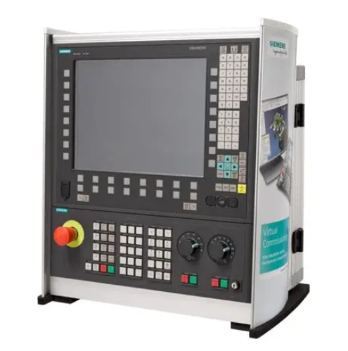
Equipment control system
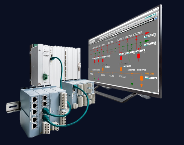
Power monitoring system
Brand
Product parameters
- Telephone:+86-15305925923
- contacts:Mr.Wang
- Email:wang@kongjiangauto.com
Description
The Profibus and DeviceNet Network Interfaces are also available with built-in I/O to
reduce cost and footprint. The network interfaces can be expanded and support all of
the RSTi I/O types.
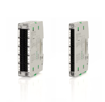
GE STXDNC132 Network Interfaces with Built-in I/O
RSTi Industrial I/OSTXDNC132 STXDNS232 STXDNS332
Product Name Slave Network Interface with
32 Negative Logic Inputs Built-in
Slave Network Interface with
32 Sink Outputs Built-in
Slave Network Interface with
32 Source Outputs Built-in
Lifecycle Status Target Release April 2012 Target Release April 2012 Target Release April 2012
Module Type Slave Network Interface Slave Network Interface Slave Network Interface
Field Busses/Device Networks DeviceNet DeviceNet DeviceNet
Protocol Supported
I/O Slave Message (Group 2 only slave),
Poll command. Bit_strobe command,
Cyclic command, COS command
I/O Slave Message (Group 2 only slave),
Poll command. Bit_strobe command,
Cyclic command, COS command
I/O Slave Message (Group 2 only slave),
Poll command. Bit_strobe command,
Cyclic command, COS command
Features
Baud Rate 125K bits/s, 250Kbps, 500Kbps
(Auto baud rate selection)
125K bits/s, 250Kbps, 500Kbps
(Auto baud rate selection)
125K bits/s, 250Kbps, 500Kbps
(Auto baud rate selection)
I/O Data Size
Total: Inputs 4 bytes/Outputs 4 bytes Total: Inputs 36 bytes/Outputs 34 bytes total
(4 bytes In/ 4 bytes Out for base
module and 32 bytes In/30 bytes Out
for expansion modules)
Total: Inputs 36 bytes/Outputs 34 bytes total
(4 bytes In/ 4 bytes Out for base
module and 32 bytes In/30 bytes Out
for expansion modules)
LEDs Module Status, Network Status, I/O Status Module Status, Network Status, I/O Status Module Status, Network Status, I/O Status
Diagnostic Supported Yes Yes Yes
Maximum Bus Length Up to 500 meters depending on baud rate Up to 500 meters depending on baud rate Up to 500 meters depending on baud rate
Maximum Number of Nodes Supported 64 64 64
Number of Expansion I/O Supported None Supported 10 10
Number of Points 32 32 32
System Power Requirement 24 VDC (11 VDC to 28.8 VDC) with Current
Limit, Reverse Polarity Protection
24 VDC (19.2 to 28.8 VDC) with Current
Limit, Reverse Polarity Protection
24 VDC (19.2 to 28.8 VDC) with Current
Limit, Reverse Polarity Protection
Field Power Requirement 24 VDC (11 VDC to 28.8 VDC) 24 VDC (11 VDC to 28.8 VDC) 24 VDC (11 VDC to 28.8 VDC)
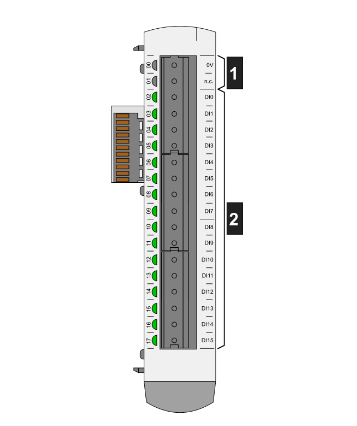
Input Type 32 Point 24 VDC Negative Logic
Input Voltage Range 24 VDC (11 VDC to 28.8 VDC)
Input Impedance ~5.4K ohms
Input Signal Delay < 0.5msec
Response Time (ms) < 0.3msec < 0.3msec
Trigger Voltage ON State: 9 VDC, OFF State: 5 VDC
Points per Common 16 32 32
Output Type 32 Point 24 VDC Negative Logic 32 Point 24 VDC Positive Logic
Output Range Nominal 0 VDC; 11 to 28.8 VDC Nominal 24 VDC; 11 to 28.8 VDC
Protection Short protection, Over Temperature
Protection, Over Current Limit
Short protection, Over Temperature
Protection, Over Current Limit
Minimum Output Load
Load Current per Point
0.5 Amps per point 0.5 Amps per point
Output Inrush Current
Polarity Sink Source
Configuration Tool EDS File EDS File EDS File
Interface Connector Type 5 pin connector 5 pin connector 5 pin connector
Power Dissipation 80 mA typical 110 mA typical 110 mA typical
Connector Type
Connector Type Spring Clamp Terminal Block Spring Clamp Terminal Block
Internal Power Used (5 VDC loading) Not Applicable 600 mA @ Maximum 5 VDC 600 mA @ Maximum 5 VDC
Dimensions (H x W x D) in mm 80 x 35 x 55 99 x 83 x 70 99 x 83 x 70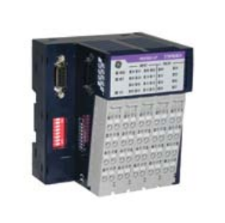
RSTi Industrial I/O
STXDNS116 STXDNS432 STXDNS532
Product Name Slave Network Interface with 16 Isolated
Relay Outputs
Slave Network Interface with 16 Positive
Logic Inputs and 16 Source Outputs
Slave Network Interface with 16 Negative
Logic Inputs and 16 Sink Outputs
Lifecycle Status Target Release April 2012 Target Release April 2012 Target Release April 2012
Module Type Slave Network Interface Slave Network Interface Slave Network Interface
Field Busses/Device Networks DeviceNet DeviceNet DeviceNet
Protocol Supported
I/O Slave Message (Group 2 only slave),
Poll command. Bit_strobe command,
Cyclic command, COS command
I/O Slave Message (Group 2 only slave),
Poll command. Bit_strobe command,
Cyclic command, COS command
I/O Slave Message (Group 2 only slave),
Poll command. Bit_strobe command,
Cyclic command, COS command”
Features
Baud Rate 125K bits/s, 250Kbps, 500Kbps
(Auto baud rate selection)
125K bits/s, 250Kbps, 500Kbps
(Auto baud rate selection)
125K bits/s, 250Kbps, 500Kbps
(Auto baud rate selection)
I/O Data Size
Total: Inputs 36 bytes/Outputs 34 bytes total
(4 bytes In/ 4 bytes Out for base
module and 32 bytes In/30 bytes Out
for expansion modules)
Total: Inputs 36 bytes/Outputs 34 bytes total
(4 bytes In/ 4 bytes Out for base
module and 32 bytes In/30 bytes Out
for expansion modules)
Total: Inputs 36 bytes/Outputs 34 bytes total
(4 bytes In/ 4 bytes Out for base
module and 32 bytes In/30 bytes Out
for expansion modules)
LEDs Module Status, Network Status, I/O Status Module Status, Network Status, I/O Status Module Status, Network Status, I/O Status
Diagnostic Supported Yes Yes Yes
Maximum Bus Length Up to 500 meters depending on baud rate Up to 500 meters depending on baud rate Up to 500 meters depending on baud rate
Maximum Number of Nodes Supported 64 64 64
Number of Expansion I/O Supported 10 10 10
Number of Points 16 16 In/ 16 Out 16 In/ 16 Out
System Power Requirement 24 VDC (19.2 to 28.8 VDC) with Current
Limit, Reverse Polarity Protection
24 VDC (19.2 to 28.8 VDC) with Current
Limit, Reverse Polarity Protection
24 VDC (19.2 to 28.8 VDC) with Current
Limit, Reverse Polarity Protection
Field Power Requirement 24 VDC (11 VDC to 28.8 VDC) 24 VDC (11 VDC to 28.8 VDC) 24 VDC (11 VDC to 28.8 VDC)
Input Type 16 Point 24 VDC Positive Logic 16 Point 24 VDC Negative Logic
Input Voltage Range 24 VDC (11 VDC to 28.8 VDC) 24 VDC (11 VDC to 28.8 VDC)
Input Impedance ~5.4K ohms ~5.4K ohms
Input Signal Delay < 0.5msec < 0.5msec
Response Time (ms) 10msec < 0.3msec < 0.3msec
Trigger Voltage ON State: 9 VDC, OFF State: 5 VDC ON State: 9 VDC, OFF State: 5 VDC
Points per Common 32 32
Output Type 16 Point Isolated Relay 16 Point 24 VDC Positive Logic 16 Point 24 VDC Negative Logic
Output Range 5 to 28.8 VDC, 48 VDC, 110 VDC, 250 VAC Nominal 24 VDC; 11 to 28.8 VDC Nominal 24 VDC; 11 to 28.8 VDC
Protection Short protection, Over Temperature
Protection, Over Current Limit
Short protection, Over Temperature
Protection, Over Current Limit
Minimum Output Load 100 micro Amps, 100 millivolts VDC per point
Load Current per Point
2 Amps at 5 to 28.8 VDC, 0.8 Amps at 48
VDC, 0.5 Amps at 110 VDC,
2 Amps at 250 VAC
0.5 Amps per point 0.5 Amps per point
Output Inrush Current
Polarity Source Sink
Configuration Tool EDS File EDS File EDS File
Interface Connector Type 5 pin connector 5 pin connector 5 pin connector
Power Dissipation 110 mA typical 110 mA typical 110 mA typical
Connector Type
Spring Clamp Terminal Block Spring Clamp Terminal Block Spring Clamp Terminal Block
Internal Power Used (5 VDC loading) 600 mA @ Maximum 5 VDC 600 mA @ Maximum 5 VDC 600 mA @ Maximum 5 VDC
Dimensions (H x W x D) in mm 99 x 83 x 70 99 x 83 x 70 99 x 83 x 70
Purchase history
| User name | Member Level | Quantity | Specification | Purchase Date |
|---|
Total 0 Record
Related products
Customer Reviews
Satisfaction :
5 Stars
No evaluation information


KONG JIANG


Add: Jimei North Road, Jimei District, Xiamen, Fujian, China
Tell:+86-15305925923


