

K-WANG


- Telephone:+86-15305925923
- contacts:Mr.Wang
- Email:wang@kongjiangauto.com
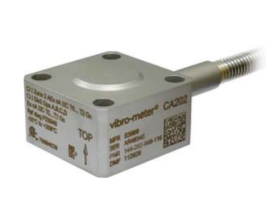
The CA202 is a piezoelectric accelerometer from
Meggitt’s vibro-meter® product line.
The CA202 sensor features a symmetrical shearmode polycrystalline measuring element with
internal case insulation in an austenitic stainlesssteel case (housing)
Vibro-Meter-CA202 piezoelectric accelerometer
The CA202 is fitted with an integral low-noise cable that is protected by a flexible stainless-steel protection hose (leaktight) which is hermetically welded to the sensor to produce a sealed leaktight assembly. The CA202 piezoelectric accelerometer is available in different versions for different industrial environments: Ex versions for installation in potentially explosive atmospheres (hazardous areas) and standard versions for use in nonhazardous areas. The CA202 piezoelectric accelerometer is designed for heavy-duty industrial vibration monitoring and measurement. For specific applications, contact your local Meggitt representative
General Input power requirements : None Signal transmission : 2-pin system, insulated from case, charge output Signal processing : Charge converter (IPC70x signal conditioner) Operating (At 23°C ±5°C, 73°F ±9°F) Sensitivity (at 120 Hz with 5 g, see Calibration on page 4) : 100 pC/g ±5% Dynamic measurement range : 0.01 to 400 g peak Overload capacity (spikes) : Up to 500 g peak Linearity • 0.01 to 20 g (peak) : ±1% • 20 to 400 g (peak) : ±2% Transverse sensitivity : ≤3% Resonant frequency : >22 kHz nominal Frequency response • 0.5 to 6000 Hz : ±5% (lower cutoff frequency is determined by the signal conditioner) • Typical deviation at 8 kHz : +10% Internal insulation resistance : 109 Ω minimum Capacitance (nominal) • Sensor : 5000 pF pin to pin. 10 pF pin to case (ground). • Cable (per metre of cable) : 105 pF/m pin to pin. 210 pF/m pin to case (ground). Environmental Temperature range • Continuous operation : −55 to +260°C (−67 to +500°F) for sensor. −55 to +200°C (−67 to +392°F) for integral cable. • Short-term survival : −70 to +280°C (−94 to +536°F) for sensor. −62 to +250°C (−80 to +482°F) for integral cable. Temperature sensitivity error (with respect to 23°C, 73°F) • −55 to +23°C (−67 to +73°F) : 0.25%/°C • +23 to 260°C (−73 to +500°F) : 0.1%/°C Corrosion, humidity • Sensor : Austenitic stainless-steel (1.4441), hermetically welded • Protection hose : Heat-resistant stainless-steel (1.4541), hermetically welded Note: The sensor and the flexible protection hose are hermetically welded to one another to create a sealed leaktight assembly that is impervious to 100% relative humidity (RH), water, steam, oil, and sea-salt atmospheres, in addition to other potential contaminants such as dust, fungus and sand. Base-strain sensitivity : 0.15 x 10⁻³ g/µε at 250 µε peak-peak Shock acceleration : ≤1000 g peak (half sine, 1 ms duration)
Approvals Conformity : European Union (EU) declaration of conformity (CE marking). EAC marking, Eurasian Customs Union (EACU) certificate/ declaration of conformity. Electromagnetic compatibility : EN 61000-6-2:2005. EN 61000-6-4:2007 + A1:2011. Electrical safety : EN 61010-1:2010 Environmental management : RoHS compliant (2011/65/EU) Hazardous areas : Ex approved versions (see Potentially explosive atmospheres on page 3) Calibration Dynamic calibration at factory at 5 g peak and 120 Hz (23°C, 73°F). No subsequent calibration necessary. Physical Case (housing) material : Austenitic stainless steel Dimensions : See Mechanical drawings on page 5 Weight • Sensor : 250 g (0.55 lb) approx. • Cable : 135 g/m (0.30 lb/m) approx. Mounting : Four M6 × 35 Allen screws and four M4 spring-lock washers with a nominal tightening torque of 15 N•m (11.1 lb-ft). Note: Electrical insulation of the mounting surface is not required. See Mounting adaptors in Accessories on page 6. Refer also to the Vibration measurement chains using CAxxx piezoelectric accelerometers installation manual. Connector : Terminated with flying leads
Type Designation Part number (PNR)
CA202 Different versions of the piezoelectric accelerometer:
Ex version with 3 m integral cable 144-202-000-106
Ex version with 6 m integral cable 144-202-000-116
Ex version with 11 m integral cable 144-202-000-126
Ex version with 20 m integral cable 144-202-000-136
Standard version with 3 m integral cable 144-202-000-206
Standard version with 6 m integral cable 144-202-000-216
Standard version with 11 m integral cable 144-202-000-226
Standard version with 20 m integral cable 144-202-000-236
Item Type Part number (PNR) Mounting adaptors MA133 Mounting adapter kit for CA20x and CE31x, with Micaver® (mica-glass) thermally isolating base. Refer to product drawing 809-133-000V011. 809-133-000-011
| User name | Member Level | Quantity | Specification | Purchase Date |
|---|


- LTI Drives
- other
- ADLINK
- Beckhoff
- Shinkawa
- Other Brands
- AMAT
- Iba
- PEPPERL+FUCHS
- Aerotech
- WATLOW
- MAN
- ADVANCED
- Abaco
- YOKOGAWA
- KOLLMORGEN
- MEGGITT
- kong-sberg
- METSO
- Motorola
- NI
- OEMAX
- RELIANCE
- scanlab
- schneider
- uniop
- Vibro-Meter
- Honeywell
- Rolls-Royce
- MOOG
- GE
- B&R
- Woodward
- Yaskawa
- xYCOM
- Siemens
- Emerson
- HIMA
- Bently
- ZYGO
- FOXBORO
- OMACO
- PROSOFT
- ENTERASYS
- TRICONEX
- Parker
- Lenze
- KEBA
- Alstom
- CTI
- ABB
- A-B

-
 Foxboro E69F-BI2 on-site installation type electric pneumatic converter (I/P)
 -
 Foxboro DCS Compact200 series RH916RB (16 slot horizontal bottom plate)
 -
 Operation Instructions for Reliance Electric PSC7000 Control Card
 -
 Eaton MTL F809F Plus DTM Operating Instructions
 -
 Motorola ACE3600 series remote terminal unit RTU
 -
 MOOG D136-003-001 Rugged Motion Controller
 -
 Micro Innovation GF1 series industrial touch screen (Micro Panel)
 -
 Neles ™ NDX ™ Compact intelligent valve controller (positioner)
 -
 Jamesbury Valv‑Powr ™ Installation, maintenance, and operation of VPVL mod D actuator
 -
 Jamesbury Valv‑Powr ™ VPVL series D-type compact gear rack pneumatic actuator
 -
 GMW IPP 144-40G Embedded Thermal Printer
 -
 Meggitt C327845 flow cut-off valve
 -
 Meggitt C422425/C422685/C422695/C422705 solenoid valve
 -
 Selection of LTi Drives ServoOne Full Series Servo Drive Systems
 -
 Jenaer Antriebstechnik ECOVARIO ® Installation and Operation Instructions for 114/214/414 Servo Drivers
 -
 Honeywell TDC3000X APM Advanced Process Manager
 -
 Honeywell Notifier NFS2-3030 Intelligent Addressing Fire Alarm Controller
 -
 Honeywell EP-DOCX-SCA-SMSC-100 Universal Signal Conditioning Wiring Solution for Safety Systems (UMS)
 -
 Installation Instructions for Honeywell XL1404 Fire Alarm Controller
 -
 Honeywell Enhanced Micro TDC 3000 (MT11-520) DCS Control System
 -
 HIMA X-DI 64 01 Digital Input Module
 -
 Hirschmann MICE MS20/MS30 Industrial Switch Installation Instructions
 -
 Exor UniOP ePAD05/ePAD06 Compact HMI Industrial Human Machine Panel
 -
 Exor Effectiveness View eV058- TST/eV058- TNT Industrial Touch Screen HMI Human Machine Panel
 -
 Esd VME-PMC CADDY/2 Intelligent VME-PMC Carrier Board
 -
 Installation Instructions for Elmo Gold Tuba (G-TUB) Servo Drive
 -
 Eaton COM-MPB1-TP/COM-MPB2-TP communication module
 -
 Delta Tau Turbo PMAC2 PCI Ultralite Programmable Multi Axis Motion Controller
 -
 DATA PATTERNS DP-VME-5114 module
 -
 CMZ SVM Series Independent Two Phase Synchronous Servo Driver SVM1608 Product Specification
 -
 SUMITOMO T2100Z steel turning
 -
 SUMITOMO PSZ Turn Modular Quick Change Tool System
 -
 SUMITOMO EGU positive front corner chip breaker groove
 -
 SUMITOMO GND series slotting and cutting tools
 -
 SUMITOMO AC8000P series (AC8115P/AC8020P/AC8025P/AC8035P) steel turning
 -
 SUMITOMO AC6000M series (AC6020M/AC6030M/AC6135M/AC6145M) stainless steel turning
 -
 SUMITOMO ELECTRIC AC5000S series (AC5005S/AC5015S/AC5025S) heat-resistant alloy turning
 -
 SUMITOMO ELECTRIC AC4000K series (AC4010K/AC4015K/AC4125K) cast iron turning
 -
 SUMITOMO ELECTRIC AC1135U small lathe for turning small parts
 -
 SUMITOMO ELECTRIC AC1030U Material Blade
 -
 CCS 6900G/6900P Non Explosion proof Pressure Switch Installation and Maintenance Manual
 -
 BENDER WR70 × 175S (P)~WR200 × 500S (P) rectangular measuring current transformer
 -
 BENDER RCMA475LY B-type residual current monitor
 -
 BENDER IRDH575 A‑ISOMETER ® Insulation monitoring device
 -
 BENDER IRDH265 / IRDH365(ISOMETER ®) Insulation monitoring device
 -
 BENDER RCMA475LY AC/DC sensitive residual current monitor
 -
 Beckwith Electric M-3425A Generator Integrated Protection Relay
 -
 Automated Logic MEx816u I/O Expansion Module
 -
 ASEM HT2150 Fanless Industrial Panel X86
 -
 Advantest U3771/U3772 portable microwave millimeter wave spectrum analyzer
 -
 Advantest R6144 Programmable DC Voltage/Current Source (Calibration Source)
 -
 Aerotech UNIDEX 100/U100i single axis motion controller
 -
 Aerotech Ndrive MP Ultra Compact PWM Digital Servo Driver
 -
 Aerotech Ndrive HPe 10/20/30 High Performance PWM Digital Servo Drive
 -
 Aerotech Ndrive Linear (HLe/ML) Linear Servo Drive
 -
 Aerotech Ndrive CP Compact PWM Digital Servo Driver
 -
 Aerotech Ndrive Linear (HLe/CL/ML) linear servo drive
 -
 Aerotech Ndrive HL (EDU176 Rev1.08b) Digital Servo Drive
 -
 Aerotech Ndrive HP10/20/30 PWM Digital Servo Drive
 -
 Aerotech Ndrive series digital servo drives
 -
 SIGMATEK TAE 1941 Touch Display Unit
 -
 SIGMATEK TAE 151 Touch Display Unit
 -
 SIGMATEK AKM series servo motor
 -
 SIGMATEK S-DIAS Control System
 -
 SIGMATEK Human Machine Interface (HMI)
 -
 SIGMATEK DIAS Drive 310-23 servo amplifier
 -
 SIGMATEK CCP 521 C-DIAS processor module
 -
 MEGMEET L6 series electric drive
 -
 Sysmex XN-1000/XN-2000 Hematology Analyzer
 -
 Sysmex XN-L series (XN-530/XN-430/XN-330) fully automatic blood cell analyzer
 -
 Sysmex XN-9000 Series Fully Automated Blood Analysis Pipeline
 -
 LTI‑Motion ServoOne Field Bus Systems PROFIBUS and PROFINET
 -
 Micro Innovation MICRO PANEL GF1 Color Touch Human Computer Interface
 -
 Micro Innovation WINbloc Distributed Remote I/O System
 -
 Micro Innovation MICRO PANEL GS-2 Industrial Touch Visualization Operation Panel (HMI)
 -
 LTi LST/LSH series synchronous servo motor
 -
 LTi CDE/CDB3000 positioning controller
 -
 ENOTEC SILOTEC ® Installation and Operation Instructions for 8000 Silo Monitoring O ₂/CO ₑ Analyzer System
 -
 ENOTEC ENSITU ® 7000 Compact Oxygen Transmitter Probe
 -
 ENOTEC COMTEC ® Installation and Operation Instructions for 6000 ATEX GasEx Explosion proof O ₂/COE Analyzer System
 -
 ENOTEC Integrated Products
 -
 ENOTEC OXITEC ® 500E Extraction Oxygen Analyzer
 -
 KUKA KR CS Box-2 Compact Controller for Four Axis SCARA Robot
 -
 KUKA KR C5 slim-2 Robot Controller
 -
 KUKA KR C5 micro With KUKA System Software (KSS/VSS) Assembly Instructions
 -
 KUKA KR C5 micro controller
 -
 KUKA KR C5 Controller Assembly Instructions
 -
 KUKA KR C5 compactcab and KR C5 small-size cab cabinets
 -
 KUKA KR C4 smallsize-2 small robot control cabinet
 -
 KUKA KR C4 Midsize/KR C4 Midsize CK Assembly Manual
 -
 ENOTEC ® Installation and Operation Instructions for 5000/5000+Oxygen Analyzer System
 -
 KUKA KR C4 extended; KR C4 extended CK Assembly Instructions Assembly Manual
 -
 Assembly/Installation Manual for KUKA KR C4 Compact Control Cabinet
 -
 KUKA Sunrise Cabinet Med Medical Collaborative Robot Special Control Cabinet
 -
 KUKA Sunrise Cabinet Next Generation Small Control Cabinet
 -
 KUKA KR C4 Smallsize-2 family's smallest control cabinet
 -
 KUKA KR C4 midsize; KR C4 midsize CK medium-sized control cabinet
 -
 KUKA KR C4 extended is a high-power multi axis control cabinet
 -
 General installation and operation instructions for KUKA KR C4 and KR C4 CK controllers
 -
 KUKA KR C4 compact controller operation instructions
 -
 Installation and Operation Instructions for KUKA Robot Arm
 -
 KUKA TITAN-2 Ultra Ground Overloading Six Axis Robot
 -
 Assembly instructions for KUKA KR SCARA-2 CS series robotic arm body
 -
 KUKA MA KR SCARA X Installation Guide
 -
 KUKA KR FORTEC-2 Ultra Heavy duty Ground Six Axis Robot Mechanical Assembly Manual
 -
 KUKA KR FORTEC-2 new generation heavy-duty ground six axis robot
 -
 KUKA Robots KR 1000 titan; KR 1000 L750 titan With F Variants Assembly Instructions
 -
 KUKA KR 600 FORTEC heavy-duty six axis ground mounted industrial robot
 -
 KUKA KR 500 MT FORTEC Heavy duty Six Axis Industrial Robot
 -
 KUKA KR 360 FORTEC Heavy duty Six Axis Industrial Robot
 -
 KUKA Sunrise Cabinet Med Medical Edition Robot Controller User Manual
 -
 KUKA Robots KR SCARA HO Assembly Instructions
 -
 KUKA Robots KR QUANTEC-2 PA Assembly Instructions
 -
 KUKA Robots KR QUANTEC-2 K and KR QUANTEC-2 P With K-F and P-C Variants Assembly Instructions
 -
 KUKA Robots KR QUANTEC-2 HO Assembly Instructions
 -
 KUKA Robots KR QUANTEC-2 HC Assembly Instructions
 -
 KUKA KR QUANTEC-2 series heavy-duty ground mounted six axis industrial robot
 -
 KUKA KR QUANTEC PA series heavy-duty palletizing robot
 -
 KUKA KR IONTEC-2 series six axis industrial robot
 -
 KUKA KR IONTEC ultra series six axis heavy-duty industrial robot
 -
 KUKA KR IONTEC HO Robot Assembly Manual
 -
 KUKA Robots KR CYBERTECH-3 HW Assembly Instructions
 -
 KUKA Robots KR CYBERTECH-3 Assembly Instructions
 -
 KUKA Robots KR CYBERTECH-2 arc Assembly Instructions
 -
 KUKA Robots KR CYBERTECH nano-2 Assembly Instructions
 -
 KUKA KR CYBERTECH CR HO (KR 20 R1810-HO) assembly instructions
 -
 KUKA Robots KR CYBERTECH With F variant Assembly Instructions
 -
 KUKA KR CYBERTECH CR (KR 20 R1810-CR) Clean Room (CR) Version 6-Axis Industrial Robot

K-JIANG

Add: Jimei North Road, Jimei District, Xiamen, Fujian, China
Tell:+86-15305925923