K-WANG

+086-15305925923
Service expert in industrial control field!
NameDescriptionContent
Adequate Inventory, Timely Service
pursuit of excellence 
Ship control system
Equipment control system
Power monitoring system
Current position:
   
Brand
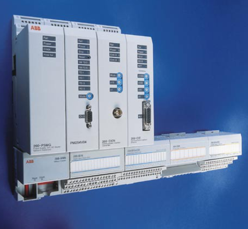
ABB RER133 Bus Connection Module
❤ Add to collection

ABB RER133 Bus Connection Module

+86-15305925923
Mr.Wang
wang@kongjiangauto.com

The RER 133 Bus Connection Module acts as an interfacing unit between an  RE_54_ host device and a SPA, Modbus or DNP 3.0 system. The RER 133 module  converts RS-232 signals to RS-485 signals. RS-485 can be connected by using 2- or  4-wire mode

11111.00
¥10000.00
Weight:2.300KG
Quantity:
(Inventory: 50)
Consultation
Product parameters
  • Telephone:+86-15305925923
  • contacts:Mr.Wang
  • Email:wang@kongjiangauto.com
Description

The RER 133 Bus Connection Module acts as an interfacing unit between an  RE_54_ host device and a SPA, Modbus or DNP 3.0 system. The RER 133 module  converts RS-232 signals to RS-485 signals. RS-485 can be connected by using 2- or  4-wire mode


ABB RER133 Bus Connection Module

The RER 133 module is connected by a cable to the RS-232 D-type connector

marked X3.2 on the rear panel of the RE_ 54_ host device. RER 133 is not a stand

alone device. An RE_ 54_ host device is always required to power the module. No

external power supply is supported.

RER 133 supports communication speeds from 300 to 19200 bits/s. Collision

detection and collision avoidance is supported for communication speeds 4800.

9600 and 19200 bits/s.

A RER 133 delivery includes the RER 133 Bus Connection Module, a connection

cable (1MRS120542) and this manual.

Principle of operation

The RER 133 Bus Connection Module is designed to work with RE_ 54_ products.

The module utilizes the RS-232 communication port located on the rear panel of the

RE_ 54_. The module is not designed to be connected to any other ABB product,

nor to any third party products.

The signal levels and the functionality of the RER 133 module are defined in the

RS-485 standard. RER 133 module is a regular type of RS-485 interface, meaning

that a maximum of 32 nodes can be connected in a daisy chain type of bus

configuration.

Collision detection on the RS-485 bus is supported when a maximum of 32 nodes

are connected to the same daisy chain. In order for collision detection to operate, the

communication speed has to be set to 4800. 9600 or 19200 bits/s. These speeds are

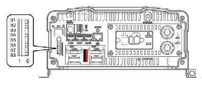
set by using the DIP switches on the front of the module. For an example on how to

set these DIP switches, please see section ìModule configurationî on page 9. When

collision detection is not used, the communication speed does not have to be set.

General

The RER 133 Bus Connection Module acts as an interfacing unit between an

RE_54_ host device and a SPA, Modbus or DNP 3.0 system. The RER 133 module

converts RS-232 signals to RS-485 signals. RS-485 can be connected by using 2- or

4-wire mode.

The RER 133 module is connected by a cable to the RS-232 D-type connector

marked X3.2 on the rear panel of the RE_ 54_ host device. RER 133 is not a stand

alone device. An RE_ 54_ host device is always required to power the module. No

external power supply is supported.

RER 133 supports communication speeds from 300 to 19200 bits/s. Collision

detection and collision avoidance is supported for communication speeds 4800.

9600 and 19200 bits/s.

A RER 133 delivery includes the RER 133 Bus Connection Module, a connection

cable (1MRS120542) and this manual.

Principle of operation

The RER 133 Bus Connection Module is designed to work with RE_ 54_ products.

The module utilizes the RS-232 communication port located on the rear panel of the

RE_ 54_. The module is not designed to be connected to any other ABB product,

nor to any third party products.

The signal levels and the functionality of the RER 133 module are defined in the

RS-485 standard. RER 133 module is a regular type of RS-485 interface, meaning

that a maximum of 32 nodes can be connected in a daisy chain type of bus

configuration.

Collision detection on the RS-485 bus is supported when a maximum of 32 nodes

are connected to the same daisy chain. In order for collision detection to operate, the

communication speed has to be set to 4800. 9600 or 19200 bits/s. These speeds are

set by using the DIP switches on the front of the module. For an example on how to

set these DIP switches, please see section ìModule configurationî on page 9. When

collision detection is not used, the communication speed does not have to be set.
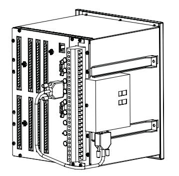
Construction and installation

The RER 133 module is mounted on the side of the RE_ 54_ host device and is

connected by the supplied cable to the 9-pin female type D-connector (X3.2) of the

RE_ 54_ host device.

A050316

Fig. 5.-1 RER 133 mounted on a REF 54_ host device

The RER 133 module consists of a printed circuit board and is housed in a metal

case. Because shielded cables and an RS-485 interface is used, special attention

must be paid to the grounding.

The dimensions of the case are: 95 mm x 101 mm x 30 mm (95 mm x 105 mm x 38

mm with mounting bracket)

Interfaces

The RS-485 bus used by SPA, Modbus and DNP 3.0 requires a daisy chain topology.

A daisy chain topology means a node-to-node connection, where nodes are chained

using cables of minimal length. The cables must be point to point, no stars, rings or

other topologies are allowed. The bus must be terminated at both ends using 120Ω

resistors. The RER 133 includes as an option the use of internal termination

resistors. These resistors are enabled through DIP switch S2.

Pull-up and pull-down resistors must be used in one of the nodes, in order for the

receivers to be able to determine the state of the bus when it is idle. These resistors

can be enabled through DIP switch S2.

Please see sections ìModule configurationî on page 9 and ìConfiguration

examplesî on page 10 for the correct settings.

The RS-232 interface (X1) of the RER 133 module is shown in Fig. 6.-1.

Fig. 6.-1 Pin usage table for the 9-pin D-type connector (X1)

The RS-485 interface of the RER 133 module is shown in Fig. 6.-2. The connector

(X2) is an 8-pin Weidm¸ller terminal block. If GND (pin 5) is used, then it is

required for all other nodes to be isolated as well.

Fig. 6.-2 Pin usage table for the Weidm¸ller terminal block (X2)

1) used for Tx in 4-wire connection

2) used for Rx in 4-wire connection

Pin Usage

1 Not connected

2 TX

3 RX

4 +15 V DC, power supply for the RER 133 module

5 GND, signal ground for power supply

6 DSR (CD/CS)

7 RTS

8 Not connected

9 Not connected A050323
Pin Signal Functionality

1 Shield GND Can be used for cable shield

grounding

2 Shield GND C Can be used for cable shield

grounding via a capacitator

3 NC Not connected
4 AGND Can be used for potential

balancing between RS-485 nodes

5 B- Differential signal B (-) 1)

6 A+ Differential signal A (+) 1)

7 B- 4-wire differential signal B (-) 2)

8 A+ 4-wire differential signal A (+) 2)

  • TRICON ®/ Installation and maintenance of E/E2/E3 transmitters
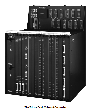
  • TRLC0NEX Tricon fault-tolerant controller
  • WAGO 221 series LEVER-NUTS ® Compact splicing connector
  • WAGO-I/O-SYSTEM 750 Programmable Fieldbus Controller ETHERNET 
  • WAGO Rail-Mount Terminal Blocks with Screw and Stud Connection
  • WAGO series molded case circuit breaker (MCCB)
  • WAGO Rail-Mount Terminal Blocks
  • WAGO I/O System 750/753 Series Distributed Automation System
  • HIMA X-CPU 01 processor module
  • Westinghouse iGen5000 Digital Inverter Generator
  • Westinghouse WGen7500DF Dual Fuel Portable Generator
  • Westinghouse WPX2700H/WPX3100H High Pressure Cleaning Machine
  • Westinghouse WH7500V portable generator
  • Westinghouse WGen9500c portable generator
  • Westinghouse DS/DSL series low-voltage power circuit breakers
  • Westinghouse ePX3500 Electric High Voltage Cleaning Machine
  • Westinghouse ST Switch Intelligent Automatic Portable Transfer Switch
  • Westinghouse 2400i digital inverter generator
  • Westinghouse iGen series digital inverter generator
  • HIMA CPU 01 Controller Module
  • Westinghouse WPX3000e/WPX3400e electric high-pressure cleaning machine
  • Westinghouse WGen2000, WGen3600, and WGen3600V portable generators
  • Westinghouse WGen5500 Generator
  • Westinghouse WGen20000 Generator
  • Westinghouse WPro8500 and WPro12000 portable generators
  • Westinghouse iGen4500DFc Dual Fuel Digital Variable Frequency Generator
  • Watlow Series L Temperature Limiting Controller
  • Watlow Series F4P Series 1/4 DIN (96 × 96mm) Temperature/Process Controller
  • Watlow EZ-ZONE ® RME (Expansion) Module
  • Watlow EZ-ZONE ® RMA (Access) module
  • Watlow PM PLUS ™ 6 Series PID Integrated Controller
  • Watlow Immersion Heater
  • Watlow F4T Controller Installation and Failure
  • Watlow DIN-A-MITE ® Style C Solid State Power Controller
  • Watlow plug-in heater
  • Watlow Series 942 Controller
  • Watlow Series 988 Controller
  • Watlow Series 146 Temperature Regulator
  • Watlow PM LEGACY ™ Limit controller
  • Johnson AE55/NIE55 Installation Guide
  • Watlow Series 96 Temperature Controller
  • Watlow PM PLUS ™ PID/Integrated Limit Controller
  • Watlow Ceramic Fiber Heater
  • Watlow Power Series microprocessor based SCR power controller
  • Watlow thermocouple products
  • Watlow Series 965 Controller
  • Watlow PM3 LEGACY ™ PID controller
  • Watlow Series 93 Controller
  • Watlow EZ-ZONE ® PM PID controller
  • Watlow CLS200 series controller
  • YAMAHA RCX40 4-axis robot controller
  • YASKAWA Z1000 series HVAC dedicated frequency converter
  • YASKAWA HV600&Z1000U series HVAC dedicated frequency converter
  • YASKAWA Power Regenerative Unit R1000 Series
  • YASKAWA AC Drive P1000 Industrial Fan and Pump Special Frequency Converter
  • YASKAWA FP605 series industrial fan pump dedicated driver
  • YASKAWA GA500 series AC micro driver
  • YASKAWA AC Drive G7 Series (Model CIMR-G7U)
  • YASKAWA U1000 series 24V power supply options (PS-U10L/PS-U10H)
  • YASKAWA GA800 industrial AC frequency converter Key issues
  • YASKAWA GA800 Industrial AC Inverter
  • YASKAWA AC Drive V1000 Compact Vector Control Drive
  • YASKAWA Control Pack CP-317M System Controller
  • YASKAWA VARISPEED-626M/656MR5 series vector control frequency converter
  • YASKAWA AC Servo Drive HR Series (CACR-HR) Multi functional/Positioning Control
  • YASKAWA MP2000 series machine controller communication module
  • Yokogawa AQ1100 series OLTS multi field tester
  • YOKOGAWA AQ7280 Optical Time Domain Reflectometer
  • YOKOGAWA AQ2200 Series Multi Application Testing System
  • YOKOGAWA AQ6150B/AQ6151B Optical Wavelength Meter
  • YOKOGAWA AQ6360 Optical Spectrum Analyzer
  • Yokogawa AQ6375E Spectral Analyzer Remote Control
  • Yokogawa DL350 Scope Order Communication Interface
  • Yokogawa 701944/701945 100:1 High Voltage Probe
  • Yokogawa CA700 pressure calibrator
  • Yokogawa DLM5000HD series high-definition oscilloscope
  • Yokogawa AQ1210 Series OTDR Multi Field Tester
  • Yokogawa AQ1000 OTDR Optical Time Domain Reflectometer
  • YOKOGAWA WT1801R series precision power analyzer communication interface
  • YOKOGAWA DLM3034HD/DLM3054HD High Definition Oscilloscope
  • YOKOGAWA AQ23011A/AQ23012A Modular Framework Equipment
  • YOKOGAWA DLM3054HD Mixed Signal Oscilloscope
  • YOKOGAWA CW500 Power Quality Analyzer
  • YOKOGAWA CA500/CA550 Multi functional Process Calibration Instrument
  • YOKOGAWA AQ7420 High-Resolution Reflectometer
  • YOKOGAWA FG410/FG420 arbitrary waveform editor
  • Yokogawa Model 701905 Conversion Cable
  • YOKOGAWA MY600 Digital Insulation Resistance Tester
  • YOKOGAWA AQ7290 Series Optical Time Domain Reflectometer OTDR
  • YOKOGAWA LS3300 AC Power Calibrator
  • Yokogawa AQ6377E Optical Spectrum Analyzer Remote Control
  • Yokogawa AQ6361 Optical Spectrum Analyzer
  • Yokogawa IS8000 Integrated Software ECU Monitoring and Synchronization Function
  • Yokogawa ROTAMASS TI Coriolis Mass Flow Meter
  • Yokogawa ROTOMETER RAMC Metal Variable Area Flow Meter
  • Yokogawa SL1000 high-speed data acquisition unit input module
  • ​Yokogawa FLXA402T turbidity and chlorine liquid analyzer Installation and wiring
  • Yokogawa WTB10-DO Series Dissolved Oxygen Measurement System Terminal Box
  • Yokogawa Model 702928 PBD0200 Differential Probe
  • YOKOGAWA ADMAG TI Series AXW Electromagnetic Flow Meter (25-450mm) Installation and Operation
  • YOKOGAWA ADMAG TI series AXW electromagnetic flowmeter (25-1800mm)
  • YOKOGAWA DO30G Dissolved Oxygen Sensor
  • YOKOGAWA SC4AJ Conductivity Sensor
  • YOKOGAWA SC210G Conductivity Detector
  • Yokogawa PH4/OR4 series pH and ORP sensor (IM12B10B00-01EN)
  • Yokogawa OR8EFG KCl filled ORP sensor (IM12C07J01-01E)
  • YOKOGAWA FU24 pH/ORP Composite Sensor with Pressure Compensation (IM 12B06J03-03EN-P)
  • Yokogawa SC200 Intelligent Two Wire Conductivity Transmitter System (IM12D08B01-01E)
  • YOKOGAWA CENTUM VP Integrated Production Control System (TI33J01A10-01EN)
  • ABB AO2000-LS25 Laser Analysts User Manual
  • YOKOGAWA FA-M3 positioning module (with analog voltage output)
  • YOKOGAWA FA-M3 Series Basic Modules
  • YOKOGAWA EJA110E Diff erential Pressure Transmitter
  • Zygo 3D Optical Profiler
  • Zygo Mark II 4-inch interferometer system
  • Zygo NewView 9000 3D Optical Contour Analyzer Core Features
  • Zygo NewView 9000 3D Optical Profilometer Technology
  • Zygo Profilometer Standard Operating Procedure
  • Zygo’s Guide to Typical Interferometer Setups
  • ZYGO Laser Interferometer Accessory Guide OMP-0463AM
  • ZYGO MetroPro 9.0 Reference Guide (OMP-0347M)
  • Zygo Device Standard Operating Procedure (SOP)
  • Zygo Verify Laser Interferometer
  • Zygo MicroLUPI interferometer
  • ZYGO ZMI-1000 Displacement Measuring Interferometer System
  • Zygo's ZMI 2000 displacement measurement interferometer system
  • ABB IGCT Technology: A Revolutionary Breakthrough in High Voltage Inverters
  • Siemens 6AG1204-2BB10-4AA3 Ethernet Switch