
K-WANG


- Telephone:+86-15305925923
- contacts:Mr.Wang
- Email:wang@kongjiangauto.com
The RER 133 Bus Connection Module acts as an interfacing unit between an RE_54_ host device and a SPA, Modbus or DNP 3.0 system. The RER 133 module converts RS-232 signals to RS-485 signals. RS-485 can be connected by using 2- or 4-wire mode
ABB RER133 Bus Connection Module
The RER 133 module is connected by a cable to the RS-232 D-type connector
marked X3.2 on the rear panel of the RE_ 54_ host device. RER 133 is not a stand
alone device. An RE_ 54_ host device is always required to power the module. No
external power supply is supported.
RER 133 supports communication speeds from 300 to 19200 bits/s. Collision
detection and collision avoidance is supported for communication speeds 4800.
9600 and 19200 bits/s.
A RER 133 delivery includes the RER 133 Bus Connection Module, a connection
cable (1MRS120542) and this manual.
Principle of operation
The RER 133 Bus Connection Module is designed to work with RE_ 54_ products.
The module utilizes the RS-232 communication port located on the rear panel of the
RE_ 54_. The module is not designed to be connected to any other ABB product,
nor to any third party products.
The signal levels and the functionality of the RER 133 module are defined in the
RS-485 standard. RER 133 module is a regular type of RS-485 interface, meaning
that a maximum of 32 nodes can be connected in a daisy chain type of bus
configuration.
Collision detection on the RS-485 bus is supported when a maximum of 32 nodes
are connected to the same daisy chain. In order for collision detection to operate, the
communication speed has to be set to 4800. 9600 or 19200 bits/s. These speeds are
set by using the DIP switches on the front of the module. For an example on how to
set these DIP switches, please see section ìModule configurationî on page 9. When
collision detection is not used, the communication speed does not have to be set.

General
The RER 133 Bus Connection Module acts as an interfacing unit between an
RE_54_ host device and a SPA, Modbus or DNP 3.0 system. The RER 133 module
converts RS-232 signals to RS-485 signals. RS-485 can be connected by using 2- or
4-wire mode.
The RER 133 module is connected by a cable to the RS-232 D-type connector
marked X3.2 on the rear panel of the RE_ 54_ host device. RER 133 is not a stand
alone device. An RE_ 54_ host device is always required to power the module. No
external power supply is supported.
RER 133 supports communication speeds from 300 to 19200 bits/s. Collision
detection and collision avoidance is supported for communication speeds 4800.
9600 and 19200 bits/s.
A RER 133 delivery includes the RER 133 Bus Connection Module, a connection
cable (1MRS120542) and this manual.
Principle of operation
The RER 133 Bus Connection Module is designed to work with RE_ 54_ products.
The module utilizes the RS-232 communication port located on the rear panel of the
RE_ 54_. The module is not designed to be connected to any other ABB product,
nor to any third party products.
The signal levels and the functionality of the RER 133 module are defined in the
RS-485 standard. RER 133 module is a regular type of RS-485 interface, meaning
that a maximum of 32 nodes can be connected in a daisy chain type of bus
configuration.
Collision detection on the RS-485 bus is supported when a maximum of 32 nodes
are connected to the same daisy chain. In order for collision detection to operate, the
communication speed has to be set to 4800. 9600 or 19200 bits/s. These speeds are
set by using the DIP switches on the front of the module. For an example on how to
set these DIP switches, please see section ìModule configurationî on page 9. When
collision detection is not used, the communication speed does not have to be set.
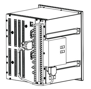
Construction and installation
The RER 133 module is mounted on the side of the RE_ 54_ host device and is
connected by the supplied cable to the 9-pin female type D-connector (X3.2) of the
RE_ 54_ host device.
A050316
Fig. 5.-1 RER 133 mounted on a REF 54_ host device
The RER 133 module consists of a printed circuit board and is housed in a metal
case. Because shielded cables and an RS-485 interface is used, special attention
must be paid to the grounding.
The dimensions of the case are: 95 mm x 101 mm x 30 mm (95 mm x 105 mm x 38
mm with mounting bracket)
Interfaces
The RS-485 bus used by SPA, Modbus and DNP 3.0 requires a daisy chain topology.
A daisy chain topology means a node-to-node connection, where nodes are chained
using cables of minimal length. The cables must be point to point, no stars, rings or
other topologies are allowed. The bus must be terminated at both ends using 120Ω
resistors. The RER 133 includes as an option the use of internal termination
resistors. These resistors are enabled through DIP switch S2.
Pull-up and pull-down resistors must be used in one of the nodes, in order for the
receivers to be able to determine the state of the bus when it is idle. These resistors
can be enabled through DIP switch S2.
Please see sections ìModule configurationî on page 9 and ìConfiguration
examplesî on page 10 for the correct settings.
The RS-232 interface (X1) of the RER 133 module is shown in Fig. 6.-1.
Fig. 6.-1 Pin usage table for the 9-pin D-type connector (X1)
The RS-485 interface of the RER 133 module is shown in Fig. 6.-2. The connector
(X2) is an 8-pin Weidm¸ller terminal block. If GND (pin 5) is used, then it is
required for all other nodes to be isolated as well.
Fig. 6.-2 Pin usage table for the Weidm¸ller terminal block (X2)
1) used for Tx in 4-wire connection
2) used for Rx in 4-wire connection
Pin Usage
1 Not connected
2 TX
3 RX
4 +15 V DC, power supply for the RER 133 module
5 GND, signal ground for power supply
6 DSR (CD/CS)
7 RTS
8 Not connected
9 Not connected A050323
Pin Signal Functionality
1 Shield GND Can be used for cable shield
grounding
2 Shield GND C Can be used for cable shield
grounding via a capacitator
3 NC Not connected
4 AGND Can be used for potential
balancing between RS-485 nodes
5 B- Differential signal B (-) 1)
6 A+ Differential signal A (+) 1)
7 B- 4-wire differential signal B (-) 2)
8 A+ 4-wire differential signal A (+) 2)
| User name | Member Level | Quantity | Specification | Purchase Date |
|---|


- other
- ADLINK
- LTI Drives
- Other Brands
- AMAT
- Iba
- PEPPERL+FUCHS
- Aerotech
- WATLOW
- MAN
- ADVANCED
- Abaco
- YOKOGAWA
- KOLLMORGEN
- MEGGITT
- kong-sberg
- METSO
- Motorola
- NI
- OEMAX
- RELIANCE
- scanlab
- schneider
- uniop
- Vibro-Meter
- Honeywell
- Rolls-Royce
- MOOG
- GE
- B&R
- Woodward
- Yaskawa
- xYCOM
- Siemens
- Emerson
- HIMA
- Bently
- ZYGO
- FOXBORO
- OMACO
- PROSOFT
- ENTERASYS
- TRICONEX
- Parker
- Lenze
- KEBA
- Alstom
- CTI
- ABB
- A-B

-
 ADLINK NuPRO-840 DV/LV Full Length PICMG Industrial Single Board Computer
 -
 ADLINK NuPRO-770 series full-length industrial single board computer
 -
 ADLINK NuPRO-595 series half length Socket 7 industrial motherboard
 -
 ADLINK cPCI-6840 series 6U CompactPCI single board computer
 -
 Foxboro 43AP series pneumatic indicator controller (PSS 3-1B3 A)
 -
 ADLINK cPCI-3720 Series 3U Low Power CompactPCI Single Board Computer
 -
 ADLINK NuPRO-E47, PICMG 1.3 full-length industrial SHB system motherboard
 -
 ADLINK NuPRO-E43 PICMG 1.3 full-length system motherboard
 -
 ADLINK NuPRO-780 series full-length industrial CPU board
 -
 ADLINK cPCI-6965 series 6U CPCI single board computer
 -
 ADLINK USB/LPCI/LPCIe-3488A GPIB interface card
 -
 Rittal SK 3241.700 Blue e+Fan Filter Unit
 -
 ADLINK cPCI-8168 6U CompactPCI 8-Axis Motion Control Card
 -
 ADLINK PCIe PXIe-8638 PCIe to PXIe Bus Expansion Kit
 -
 ADLINK PCIe GIE7x series acquisition card
 -
 ADLINK PCIe-7396 96 96 channel TTL digital IO card
 -
 ADLINK PCI/MPC/PXI-8164 Three in One Motion Control Card
 -
 ADLINK PCI-8154 Four Axis Pulse Motion Control Card
 -
 ADLINK PCI-8134 Four Axis Servo/Stepper Motion Control Card
 -
 ADLINK NuPRO-E42 PICMG1.3 full-length SHB motherboard
 -
 ADLINK MXC-6600 series high-performance fanless extended industrial computer
 -
 ADLINK MXC-6000 series embedded industrial control computer
 -
 ADLINK MXC-2300 series fanless expandable embedded industrial computer
 -
 ADLINK MCM-204 Independent Ethernet DAQ User Manual
 -
 ADLINK MCM-100/102 Edge IoT Platform for Machine Condition Monitoring User’s Manual
 -
 ADLINK MXC-6400 series sixth generation Core Fanless Scalable Industrial Control Computer
 -
 ADLINK Matrix Full Series Fanless Embedded Industrial Control Computers
 -
 ADLINK GIE64+4-channel PoE Gigabit Vision Capture Card
 -
 Honeywell UMS Security System Troubleshooting Guide
 -
 Honeywell Expert Series-C I/O Module
 -
 ADLINK EOS-1200 Embedded Vision Host
 -
 ADLINK DLAP-5200 series high-performance fanless AI industrial computer
 -
 ADLINK DLAP-4000 series embedded industrial control computer
 -
 ADLINK Matrix MXC-2000 Series Fanless Industrial Control Computer Specification
 -
 ADLINK DAQ -/DAQE -/PXI-2000 Series Multi functional Synchronous Acquisition Card
 -
 ADLINK cPCI-6520 6U CompactPCI Single Board Computer
 -
 ADLINK CM1-86DX3 PC/104 Single Board Computer
 -
 Honeywell DC1000 series PID temperature controller
 -
 ALSTOM MiCOM C264 Modular Substation Controller
 -
 EMERSON AMS 2140 Mechanical Health Analyzer
 -
 ADLINK NuPRO-E320 PICMG1.3 Full length Industrial Motherboard
 -
 ADLINK NuPRO-800 Series Full length Industrial SBC User Manual
 -
 ADLINK NuPRO-598 Industrial Single Board Computer
 -
 ADLINK MXC-6300 Fanless Embedded Industrial Control Computer
 -
 ADLINK Express-BASE7 User Manual
 -
 ADLINK DLAP-211 Series Fanless Edge AI Platform Specification Manual
 -
 ADLINK PCI/LPCI/LPCIe/cPCI-723X series 32 channel isolated digital I/O card
 -
 ADLINK cPCI-6965 series 6U CompactPCI single board computer
 -
 ADLINK NuDAQ 7200 series high-speed digital I/O board
 -
 Linghua ADLINK DLAP Deep Learning Acceleration Platform Product Manual
 -
 DEIF TCM-2 thyristor control module
 -
 Installation Manual for DEIF MVR-200 Series Medium Voltage Protection Device
 -
 DEIF MDR-2 multifunctional differential relay
 -
 DEIF AOM-1 Analog Output Module
 -
 DEIF AGI 400 series industrial/marine touch screen
 -
 Installation Manual for DEIF BRW-1 Marine Wing Bridge Instrument
 -
 DEIF AGC200 Quick Start Guide
 -
 DEIF AGC Multi line 2 Generator Set ControllerProduct basic information
 -
 ABB SPA-ZC 400 Ethernet Gateway Installation and Debugging Manual
 -
 ABB REM 543/545 motor generator protection device
 -
 DEIF PPU 300 controller
 -
 DEIF Delomatic 4 Offshore/Ocean Platform Dedicated Generator Power Management System DM-4
 -
 DEIF Delomatic Modular Generator Set Integrated System
 -
 DEIF AGC-4 Mk II Generator Set Controller
 -
 DEIF AGC-4 diesel generator set integrated controller
 -
 DEIF Multi line 2 Series PPU Unit Power Management (PPM) Operation Manual
 -
 DEIF Multi line 2 V2.4X Installation Manual
 -
 Beckwith M-6280 Digital Capacitor Bank Controller
 -
 Beckwith M-3311 Transformer Protection Relay
 -
 Beckwith M-3311A Transformer Integrated Protection Device
 -
 Beckwith M-3310 Transformer Integrated Protection Device Specification
 -
 Beckwith M-0359 Syncrocloser Check Plus Application Guide for Synchronous Calibration Relay
 -
 Beckwith M-0293A On Load Tap changer Controller Application Guide
 -
 DEIF GPU-3 Synchronous/Asynchronous Generator Integrated Microcomputer Protection Controller
 -
 Installation Instructions for DEIF PPM-3
 -
 Beckwith M-3520 distributed power grid connected comprehensive protection device
 -
 Beckwith M-3430 generator comprehensive protection device
 -
 Beckwith M-2293B adapter panel
 -
 Beckwith M-2001C digital on load voltage regulator controller
 -
 Beckwith M-2001B Digital On Load Voltage Regulating Controller
 -
 Beckwith M-0388/M-0389 synchronous verification relay
 -
 Beckwith M-0193B synchronous closing device
 -
 Beckwith M-0115A Transformer Parallel Balancing Module
 -
 Beckwith M-0067E on load tap changer controller
 -
 Beckwith M-4272 Digital Motor Bus Switching System
 -
 Beckwith M-3311A Transformer Integrated Protection Device
 -
 Beckwith M-3425A Generator Integrated Protection Device Manual
 -
 Basler BE1-27/BE1-59/BE1-27/59 undervoltage/overvoltage relay
 -
 Basler AVC63-12/AVC125-10 excitation voltage regulator
 -
 Basler L301kc Color Three Line Array Camera Operation Manual
 -
 Basler CBS 212A Current Enhanced Excitation System
 -
 Basler BE3-25 synchronous check relay
 -
 Operation Manual for Basler BE1-32R/BE1-32O/U Direction Power Relay
 -
 Basler Electric PRS-250 Veri Sync Synchronous Relay
 -
 Basler Pilot Series Area Array Industrial Camera piA2400-17gc
 -
 Basler BE1-11g comprehensive protection device for generator
 -
 Basler VR63-4C/UL Analog Excitation Voltage Regulator
 -
 Basler BE1-DFPR distribution feeder protection relay
 -
 Basler CBS310/CBS320 current strong excitation system
 -
 Basler UFOV250A/UFOV260A Low Frequency Overvoltage Module
 -
 Basler MVC104/MVC108/MVC232 manual voltage control device
 -
 Basler XR2002/XR2002F PMG excitation regulator
 -
 Basler DECS-400 Digital Excitation Control System
 -
 Basler DGC-2020 Digital Generator Set Controller
 -
 Basler MVC-300 Electronic Manual Excitation Controller
 -
 Basler MVC-104/MVC-108/MVC-232 manual excitation controller
 -
 Basler SSR32-12/SSR63-12/SSR125-12 Static Excitation Voltage Regulator
 -
 Basler SR4A/SR8A Analog Excitation Voltage Regulator
 -
 Basler BE2000E Digital Excitation Voltage Regulator
 -
 Basler DECS-2100 Digital Excitation System
 -
 Basler BE1-851 Overcurrent Protection Device Manual
 -
 Basler APR 63-5 Voltage Regulator
 -
 Basler BE1-FLEX Integrated Protection Control System
 -
 Basler BE1-700V digital voltage protection relay
 -
 Basler BE1-87B high impedance bus differential relay
 -
 Basler BE1-40Q demagnetization relay
 -
 Basler BE1-60 Voltage Balance Relay
 -
 Basler BE1-47N negative sequence voltage phase sequence relay
 -
 Basler BE1-81O/U digital frequency relay
 -
 Basler BE1-11f Feedline Integrated Protection Device Manual
 -
 Basler DECS-250 Digital Excitation Control System
 -
 Basler DECS-100 Digital Excitation Control System
 -
 Basler BE1-BPR Circuit Breaker Protection Relay
 -
 Basler BE1-50/51B-255 overcurrent relay
 -
 Basler BE1-25 synchronous check relay
 -
 Basler BE1-51 microcomputer time limited overcurrent relay
 -
 Basler DECS-300 Digital Excitation Control System
 -
 Mitsubishi MELSEC-F FX series programmable controllers

K-JIANG

Add: Jimei North Road, Jimei District, Xiamen, Fujian, China
Tell:+86-15305925923