
K-WANG


- Telephone:+86-15305925923
- contacts:Mr.Wang
- Email:wang@kongjiangauto.com
These Application Notes are a guide to applying the G122-829A001 P-I Servoamplifier. These Application Notes can be used to: Determine the closed loop structure for your application. Select the G122-829A001 for your application. Refer also to data sheet G122-829. Use these Application Notes to determine your system configuration. Draw your wiring diagram. Install and commission your system. Aspects, such as hydraulic design, actuator selection, feedback transducer selection, performance estimation, etc. are not covered by these Application Notes. The G122-202 Application Notes (part no C31015) cover some of these aspects. Moog Application Engineers can provide more detailed assistance, if required.
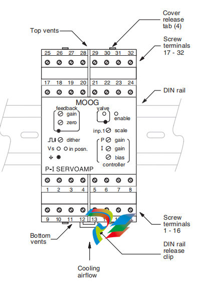
MOOG-G122-829A001-P-I Servoamplifier
2 Description The G122-829A001 is a general purpose, user configurable, P-I servoamplifier. Selector switches inside the amplifier enable either proportional control, integral control, or both to be selected. Many aspects of the amplifier’s characteristics can be adjusted with front panel pots or selected with internal switches. This enables one amplifier to be used in many different applications. Refer also to data sheet G122-829.
3 Installation 3.1 Placement A horizontal DIN rail, mounted on the vertical rear surface of an industrial steel enclosure, is the intended method of mounting. The rail release clip of the G122-829A001 should face down, so the front panel and terminal identifications are readable and so the internal electronics receive a cooling airflow. An important consideration for the placement of the module is electro magnetic interference (EMI) from other equipment in the enclosure. For instance, VF and AC servo drives can produce high levels of EMI. Always check the EMC compliance of other equipment before placing the G122-829A001 close by.
3.2 Cooling Vents in the top and bottom sides of the G122-829A001 case provide cooling for the electronics inside. These vents should be left clear. It is important to ensure that equipment below does not produce hot exhaust air that heats up the G122-829.
3.3 Wiring The use of crimp “boot lace ferrules” is recommended for the screw terminals. Allow sufficient cable length so the circuit card can be withdrawn from its case with the wires still connected. This enables switch changes on the circuit card to be made while the card is still connected and operating. An extra 100mm, for cables going outside the enclosure, as well as wires connecting to adjacent DIN rail units, is adequate. The screw terminals will accommodate wire sizes from 0.2mm2 to 2.5mm2 (24AWG to 12AWG). One Amp rated, 0.2mm2 should be adequate for all applications.
3.4 EMC The G122-829A001 emits radiation well below the level called for in its CE mark test. Therefore, no special precautions are required for suppression of emissions. However, immunity from external interfering radiation is dependent on careful wiring techniques. The accepted method is to use screened cables for all connections and to radially terminate the cable screens, in an appropriate grounded cable gland, at the point of entry into the industrial steel enclosure. If this is not possible, chassis ground screw terminals are provided on the G122-829A001. Exposed wires should be kept to a minimum length. Connect the screens at both ends of the cable to chassis ground.
6.2 Input 1 An input to the error amplifier: This input is ±10V non-inverting and has two important features: It has a scale pot on its input that enables large inputs to be scaled down to match smaller signals on other inputs. Scale range is 10 to 100%. Set fully clockwise (FCW), an input of 100V can match a 10V signal on the other inputs. Note that the maximum permissable input voltage is ±95V. It has a switch selectable (SW4:2) lag of 55mS that can be used to remove transients from the input signal that could cause unwanted rapid movement in the output. Input 1 is well suited to be a command because of these two features. If input 1 is used for feedback, be sure the lag is switched off. Input resistance after the scale pot is 94k Ohms. 6.3 Input 2 An input to the error amplifier: This input is differential, with non-inverting and inverting inputs. It is switch selectable (SW5) between 4-20mA and ±10V. The 4-20mA converter produces 0 to +10V for 4 to 20mA input to terminal 7. R34 connects from the output of the amplifier to the input of the error amp. It is a plug-in resistor with a default value of 100k Ohms, giving a nominal ±10V input signal range when V is selected. Input 2 is suitable for command or feedback. R34 can be increased to give a larger input range. Terminal 8. the inverting input, can be connected to ground with SW6:1. 6.4 Input 3 An input to the output summing and limiting amplifier via a plug-in resistor, R33. A typical use for this input is command feed forward or closing the outer loop of a three stage valve. With R33 at 10k Ohm, a ±10V input will produce ±100% valve drive. Increasing R33 reduces the valve drive. The summing amp gain can be changed with plug-in resistor R27. This is useful if input 3 is being used to close the outer loop of a three stage valve. 7 Output configuration Select the output to match the input requirements of the valve (SW2). When voltage (V) is selected, ±10V is available into a minimum load of 200 Ohm. When current (I) is selected, the current level switches (SW1:X) enable ±5 to ±100mA to be selected. The switch selections sum, so, if for instance 45mA is required, select 30.10 and 5. The output can drive all known Moog valves up to ±100mA. The maximum load at I (Amp) output is: RL max = 11V – 39 Ohm I (Amp) eg. at 50mA RL max is 181 Ohm When 4-20mA is selected, the output V/I switches must be in I and the output current SW1 must have switch 3 selected for 20mA. Maximum load for 4-20mA output is 500 Ohm. The output amplifier is limited to approximately 105% of the selected full scale output. If both the proportional and integrator stages are saturated, the output will not be twice the selected full scale but still only 105% of full scale. 8 Step push button The step push button (SW3) injects -50% valve drive disturbance into the output. When released, the valve drive reverts to its original level. This feature is useful for closed loop gain optimisation.
9 P-I selection For position closed loops, initially select only P (SW6:2). For pressure or velocity loops select I (SW6:4) initially and then P. See paragraph 12 below for more detail. For a complete discussion of P and I control, see the G122-202 servoamplifier Application Notes (part no C31015). 10 Integrator input The servoamplifier has a unity gain input error amplifier followed by two parallel stages, one a proportional amplifier and the other an integrator. The outputs of these two stages can be switched to the output power amplifier (see paragraph 7 above) which then drives the valve. The input to the integrator stage can be switch selected (SW4:1) from either the output of the error amplifier, I in = E, or the output of the proportional stage, I in = P. The latter arrangement is used in the G122-202. It is beyond the scope of these Application Notes to detail the benefits of each arrangement. If you have experience with the G122-202. I in = P would seem to be an easy choice. 11 P only gain For position loops select only P control (SW6:2). Input a step disturbance of 50% valve current with the step push button (SW3). Adjust the P gain for the required stability, while monitoring the front panel valve test point, or the feedback signal. The gain range of the proportional amplifier can be moved by changing the plug-in resistor R17. The value loaded when shipped is 100k Ohms, which gives a 1 to 20 range. Selecting 200k Ohms will give 2 to 40. The circuit will function correctly with the value of R17 between 100k Ohms and 10M Ohms. Note that as P gain is increased, the movement due to the step push button decreases. 12 P and I gains together If you are inexperienced with integral control the following set-up method is a good starting point. I in = E: Initially select only I (SW6:4). Press the step push button (SW3). Increase I gain until one overshoot in the feedback signal is observed. Next select P (SW6:2) and I (SW6:4) together and increase the P gain to reduce the overshoot. For the I in = E arrangement the P and I sequence could be reversed. i.e.: adjust P first, followed by I. I in = P: For an I in = P arrangement, only the “P followed by I” sequence of adjustment can be used. For a more thorough discussion see G122-202 Application Notes (part no C31015). 13 I limit The contribution from the integrator to the output amplifier can be reduced by selecting I limit on (SW6:3). When this switch is on the integrator contribution is reduced to approximately 15% of the level when it is off. This feature is useful in a position loop that may require integral control to achieve the required steady state accuracy. The limited integral control removes valve null error when the final position is reached. It is also useful in a pressure loop to limit overshoot, if the valve drive saturates.
| User name | Member Level | Quantity | Specification | Purchase Date |
|---|


- other
- LTI Drives
- ADLINK
- Beckhoff
- Other Brands
- AMAT
- Iba
- PEPPERL+FUCHS
- Aerotech
- WATLOW
- MAN
- ADVANCED
- Abaco
- YOKOGAWA
- KOLLMORGEN
- MEGGITT
- kong-sberg
- METSO
- Motorola
- NI
- OEMAX
- RELIANCE
- scanlab
- schneider
- uniop
- Vibro-Meter
- Honeywell
- Rolls-Royce
- MOOG
- GE
- B&R
- Woodward
- Yaskawa
- xYCOM
- Siemens
- Emerson
- HIMA
- Bently
- ZYGO
- FOXBORO
- OMACO
- PROSOFT
- ENTERASYS
- TRICONEX
- Parker
- Lenze
- KEBA
- Alstom
- CTI
- ABB
- A-B

-
 ADLINK ACL-7225 ISA 16 channel relay output+16 channel isolated digital input card
 -
 ADLINK DAQ-2000 series synchronous acquisition card
 -
 ADLINK NuPRO-E330 PICMG 1.3 full-length industrial motherboard (SHB)
 -
 ADLINK ACL-8112 series multifunctional ISA acquisition card
 -
 ADLINK USB-2405 24 bit dynamic signal acquisition module
 -
 ADLINK PXIS-3320 15 slot 6U PXI chassis
 -
 ADLINK PCIe GIE7x series acquisition card
 -
 ADLINK PCIe-7856/PCIe-7853 Distributed Motion and IO Main Controller PCIe Acquisition Card
 -
 ADLINK PCI-6308 series isolated analog output board
 -
 ADLINK PCI-7432 Isolated Digital I/O Acquisition Card
 -
 ADLINK NuPRO-E72 PICMG 1.3 Full length Industrial SHB Single Board Computer
 -
 ADLINK MXE-5400 series fanless embedded industrial computer
 -
 ADLINK M-322 Industrial ATX Motherboard
 -
 ADLINK IMB-M43H Industrial ATX Motherboard
 -
 ADLINK IMB-M42H Industrial ATX Motherboard
 -
 ADLINK i915GV-INA ATX motherboard
 -
 ADLINK ETX-NR667 Embedded ETX Standard Computer Module
 -
 ADLINK ETX-BT (PATA to SATA version) User Manual
 -
 ADLINK CM1-BT1 PC/104 Single Board Computer
 -
![ADLINK cPCI-8217 [R] 3U CompactPCI VGA/LCD Display Module](https://aosspic10001.websiteonline.cn/hkw632bc8/image/image_aJXQRn.png) ADLINK cPCI-8217 [R] 3U CompactPCI VGA/LCD Display Module
ADLINK cPCI-8217 [R] 3U CompactPCI VGA/LCD Display Module -
 ADLINK AmITX-SL-G Mini ITX Embedded Motherboard
 -
 ADLINK AmITX-AL-I ultra-thin Mini ITX industrial motherboard
 -
 ADLINK NuPRO-E315 Full length PICMG 1.3 Industrial SHB Single Board Computer
 -
 ADLINK NuPRO-842 Full length PICMG 1.0 PCI/ISA Industrial Single Board Computer
 -
 ADLINK NuPRO-900A PICMG 1.2 ePCI-X Dual Xeon Industrial System Motherboard (SHB)
 -
 ADLINK cPCI-6910 series 6U CompactPCI single board computer
 -
 ADLINK cPCI-6860A 6U CompactPCI dual core single board computer with cPCI-R6860A rear adapter board
 -
 ADLINK cPCI-8168 6U CompactPCI Eight Axis Motion Control Card
 -
 ADLINK NuPRO-E340 PICMG 1.3 Industrial SHB motherboard
 -
 ADLINK NuPRO-A40H Full length PICMG1.0 Industrial Single Board Computer (SBC)
 -
 ADLINK NuPRO-852 Full length PICMG1.0 Industrial Single Board Computer
 -
 ADLINK NuPRO-841 Full length Industrial SBC
 -
 ADLINK NuPRO-590/591/592 series Socket7 full-length industrial SBC
 -
 ADLINK MXE-5500 series fanless embedded industrial computer
 -
 ADLINK MXE-200/200i Fanless Embedded Machine
 -
 ADLINK cPCI-6770 series CompactPCI CPU board
 -
 ADLINK NuPRO-A301 standard PICMG 1.0 full-length industrial SBC single board computer
 -
 ADLINK NuPRO-965 PICMG 1.3 SHB Express Full length Industrial Motherboard
 -
 ADLINK NuPRO-935A Full length PICMG1.0 Industrial Single Board Computer
 -
 ADLINK NuPRO-865 Full length Single Board Computer
 -
 ADLINK NuPRO-840 DV/LV Full Length PICMG Industrial Single Board Computer
 -
 ADLINK NuPRO-770 series full-length industrial single board computer
 -
 ADLINK NuPRO-595 series half length Socket 7 industrial motherboard
 -
 ADLINK cPCI-6840 series 6U CompactPCI single board computer
 -
 Foxboro 43AP series pneumatic indicator controller (PSS 3-1B3 A)
 -
 ADLINK cPCI-3720 Series 3U Low Power CompactPCI Single Board Computer
 -
 ADLINK NuPRO-E47, PICMG 1.3 full-length industrial SHB system motherboard
 -
 ADLINK NuPRO-E43 PICMG 1.3 full-length system motherboard
 -
 ADLINK NuPRO-780 series full-length industrial CPU board
 -
 ADLINK cPCI-6965 series 6U CPCI single board computer
 -
 ADLINK USB/LPCI/LPCIe-3488A GPIB interface card
 -
 Rittal SK 3241.700 Blue e+Fan Filter Unit
 -
 ADLINK cPCI-8168 6U CompactPCI 8-Axis Motion Control Card
 -
 ADLINK PCIe PXIe-8638 PCIe to PXIe Bus Expansion Kit
 -
 ADLINK PCIe GIE7x series acquisition card
 -
 ADLINK PCIe-7396 96 96 channel TTL digital IO card
 -
 ADLINK PCI/MPC/PXI-8164 Three in One Motion Control Card
 -
 ADLINK PCI-8154 Four Axis Pulse Motion Control Card
 -
 ADLINK PCI-8134 Four Axis Servo/Stepper Motion Control Card
 -
 ADLINK NuPRO-E42 PICMG1.3 full-length SHB motherboard
 -
 ADLINK MXC-6600 series high-performance fanless extended industrial computer
 -
 ADLINK MXC-6000 series embedded industrial control computer
 -
 ADLINK MXC-2300 series fanless expandable embedded industrial computer
 -
 ADLINK MCM-204 Independent Ethernet DAQ User Manual
 -
 ADLINK MCM-100/102 Edge IoT Platform for Machine Condition Monitoring User’s Manual
 -
 ADLINK MXC-6400 series sixth generation Core Fanless Scalable Industrial Control Computer
 -
 ADLINK Matrix Full Series Fanless Embedded Industrial Control Computers
 -
 ADLINK GIE64+4-channel PoE Gigabit Vision Capture Card
 -
 Honeywell UMS Security System Troubleshooting Guide
 -
 Honeywell Expert Series-C I/O Module
 -
 ADLINK EOS-1200 Embedded Vision Host
 -
 ADLINK DLAP-5200 series high-performance fanless AI industrial computer
 -
 ADLINK DLAP-4000 series embedded industrial control computer
 -
 ADLINK Matrix MXC-2000 Series Fanless Industrial Control Computer Specification
 -
 ADLINK DAQ -/DAQE -/PXI-2000 Series Multi functional Synchronous Acquisition Card
 -
 ADLINK cPCI-6520 6U CompactPCI Single Board Computer
 -
 ADLINK CM1-86DX3 PC/104 Single Board Computer
 -
 Honeywell DC1000 series PID temperature controller
 -
 ALSTOM MiCOM C264 Modular Substation Controller
 -
 EMERSON AMS 2140 Mechanical Health Analyzer
 -
 ADLINK NuPRO-E320 PICMG1.3 Full length Industrial Motherboard
 -
 ADLINK NuPRO-800 Series Full length Industrial SBC User Manual
 -
 ADLINK NuPRO-598 Industrial Single Board Computer
 -
 ADLINK MXC-6300 Fanless Embedded Industrial Control Computer
 -
 ADLINK Express-BASE7 User Manual
 -
 ADLINK DLAP-211 Series Fanless Edge AI Platform Specification Manual
 -
 ADLINK PCI/LPCI/LPCIe/cPCI-723X series 32 channel isolated digital I/O card
 -
 ADLINK cPCI-6965 series 6U CompactPCI single board computer
 -
 ADLINK NuDAQ 7200 series high-speed digital I/O board
 -
 Linghua ADLINK DLAP Deep Learning Acceleration Platform Product Manual
 -
 DEIF TCM-2 thyristor control module
 -
 Installation Manual for DEIF MVR-200 Series Medium Voltage Protection Device
 -
 DEIF MDR-2 multifunctional differential relay
 -
 DEIF AOM-1 Analog Output Module
 -
 DEIF AGI 400 series industrial/marine touch screen
 -
 Installation Manual for DEIF BRW-1 Marine Wing Bridge Instrument
 -
 DEIF AGC200 Quick Start Guide
 -
 DEIF AGC Multi line 2 Generator Set ControllerProduct basic information
 -
 ABB SPA-ZC 400 Ethernet Gateway Installation and Debugging Manual
 -
 ABB REM 543/545 motor generator protection device
 -
 DEIF PPU 300 controller
 -
 DEIF Delomatic 4 Offshore/Ocean Platform Dedicated Generator Power Management System DM-4
 -
 DEIF Delomatic Modular Generator Set Integrated System
 -
 DEIF AGC-4 Mk II Generator Set Controller
 -
 DEIF AGC-4 diesel generator set integrated controller
 -
 DEIF Multi line 2 Series PPU Unit Power Management (PPM) Operation Manual
 -
 DEIF Multi line 2 V2.4X Installation Manual
 -
 Beckwith M-6280 Digital Capacitor Bank Controller
 -
 Beckwith M-3311 Transformer Protection Relay
 -
 Beckwith M-3311A Transformer Integrated Protection Device
 -
 Beckwith M-3310 Transformer Integrated Protection Device Specification
 -
 Beckwith M-0359 Syncrocloser Check Plus Application Guide for Synchronous Calibration Relay
 -
 Beckwith M-0293A On Load Tap changer Controller Application Guide
 -
 DEIF GPU-3 Synchronous/Asynchronous Generator Integrated Microcomputer Protection Controller
 -
 Installation Instructions for DEIF PPM-3
 -
 Beckwith M-3520 distributed power grid connected comprehensive protection device
 -
 Beckwith M-3430 generator comprehensive protection device
 -
 Beckwith M-2293B adapter panel
 -
 Beckwith M-2001C digital on load voltage regulator controller
 -
 Beckwith M-2001B Digital On Load Voltage Regulating Controller
 -
 Beckwith M-0388/M-0389 synchronous verification relay
 -
 Beckwith M-0193B synchronous closing device
 -
 Beckwith M-0115A Transformer Parallel Balancing Module
 -
 Beckwith M-0067E on load tap changer controller
 -
 Beckwith M-4272 Digital Motor Bus Switching System
 -
 Beckwith M-3311A Transformer Integrated Protection Device
 -
 Beckwith M-3425A Generator Integrated Protection Device Manual
 -
 Basler BE1-27/BE1-59/BE1-27/59 undervoltage/overvoltage relay

K-JIANG

Add: Jimei North Road, Jimei District, Xiamen, Fujian, China
Tell:+86-15305925923