

K-WANG


- Telephone:+86-15305925923
- contacts:Mr.Wang
- Email:wang@kongjiangauto.com
Manufacturers
ABB
Model(s)
ABB Advant Controller 31, ABB Advant OCS
Additional Information
8 relays binary outputs 120 V AC
Estimated Shipping Size
Dimensions: 4.0" x 3.0" x 4.0"
(10.2 cm x 7.6 cm x 10.2 cm)
Weight: 0 lbs 7.1 oz (0.2kg )
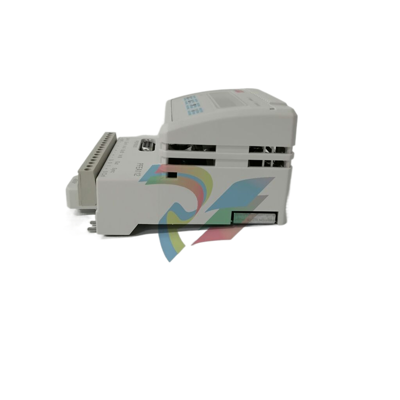
ABB 1SBP260601R1001 XO08R1 Extension Module
Basic Information
Model and name: ABB 1SBP260601R1001 XO08R1 Extension Module, ‘1SBP260601R1001’ is the model number of the product, ‘XO08R1’ may XO08R1’ may indicate that it has a specific function or configuration. This is an extension module used to extend the functionality of the system, such as adding input/output interfaces.
Family: belongs to the ABB industrial automation control device family. In this series, there are various controllers, input/output modules, communication modules, etc. This extension module can be used in conjunction with other modules to complete the function of the whole automation control system.
Application Scenario Related: Widely used in industrial automation production line, process control system (chemical, pharmaceutical, electric power and other industries), intelligent building automation system and other scenarios. For example, it is used to expand the input/output points of PLC (Programmable Logic Controller) in automated production lines to connect more sensors and actuators; in process control systems, it can add more signal acquisition and control channels for the controller to enhance the system's ability to monitor and control complex processes.
Functional Features
Expansion Function
Input / Output Expansion: The main function is to expand the input and output interfaces of the system. It may provide additional digital input channels, digital output channels, analogue input channels or analogue output channels, depending on the product design. For example, 8 digital input channels and 8 digital output channels may be added, or a certain number of analogue input/output channels may be provided for connecting additional field devices such as sensors (temperature, pressure, level, etc.) and actuators (valves, motors, etc.).
Function extension: Besides simple input/output extension, other function extensions may be provided. For example, support for some special signal processing functions, such as pulse counting, frequency measurement, etc., or the ability to implement simple logic control functions, reducing the burden on the main controller and improving the overall performance and flexibility of the system.
Compatibility and Connectivity
Compatible with mains equipment: designed to be highly compatible with ABB's main controllers or other core equipment. It can seamlessly communicate and interact with data from the main device to ensure stable operation of the expanded system. This compatibility may be reflected in a variety of aspects such as communication protocols, electrical interfaces, data formats, etc. For example, the same communication protocols as the main controller (e.g. Profibus, Modbus, etc.) are used for data transmission.
Multiple connection methods: A variety of connection methods are available to facilitate connection to other devices. These may include standard electrical interfaces, such as screw terminals, plug-in connectors, etc., for connecting input/output signal lines; at the same time, they may also support network connections, such as communicating with other devices in the system via Ethernet interfaces or other fieldbus interfaces to achieve distributed expansion and control.
Reliability and Stability
Industrial-grade design: Adopting industrial-grade design standards, it can operate stably in harsh industrial environments. Its shell has a certain protection level, such as IP20 or higher, which can prevent the intrusion of external objects and prevent personnel from accidentally contacting the internal circuit; the internal circuit is reinforced and anti-interference design, which can resist the influence of electromagnetic interference, temperature change, humidity change and other unfavourable factors in the industrial site.
Redundancy design (possible): Some of the high-end expansion modules may have redundancy design, for example, adopting redundancy backup in the communication line or key circuit part to improve the reliability of the module. When one of the communication channels or circuits fails, it can automatically switch to the backup channel or circuit to ensure the normal operation of the system.
Technical Parameters
Electrical Parameters
Working voltage range: the working voltage is generally DC voltage, the range may be around 18V - 30V DC, which can adapt to the common power supply situation in the industrial field, to ensure that the module can work stably under different power conditions.
Input/Output Signal Voltage and Current Range: For the digital input channel, it may support a variety of voltage ranges, such as 5V - 30V DC dry contact signals or TTL/CMOS level signals; the digital output channel is able to provide a certain driving current, such as the maximum output current of each channel is 0.5A - 1A, which can be used to drive the external devices. For analogue input channels, they may be compatible with 0 - 10V voltage signals, 4 - 20mA current signals, etc. Analogue output channels have a similar output range and a certain output accuracy, e.g. ±0.1% - ±0.5%.
Power Consumption: Power consumption is low, usually between a few watts and a dozen watts, depending on the module's operating status (e.g., number of channels in use, frequency of signal processing, etc.) and the module's design. The low power consumption design helps to run stably for a long time in industrial environments, and it can reduce the heat generated by the equipment and improve the reliability of the equipment.
Performance Parameters
Number and type of input/output channels: As mentioned earlier, the number and type of channels varies from product to product. There may be 8 digital input channels and 8 digital output channels, or 4 analogue input channels and 4 analogue output channels in different configurations. The response time of the channels is also fast, typically between microseconds and milliseconds for the digital input channels, while the analogue input channels may have a sampling frequency of thousands of times per second to meet the needs of fast data acquisition in the industrial field.
Signal processing capability: In terms of signal processing, it has a certain degree of precision and speed. For example, for the conversion of analogue signals (analogue - digital or digital - analogue) with high accuracy, may reach between ±0.1% - ±0.5%; for the logic processing of digital signals (such as with, or, or non-logic operations) faster, able to complete the basic logic operations in microseconds time.
| User name | Member Level | Quantity | Specification | Purchase Date |
|---|


- LTI Drives
- other
- ADLINK
- Beckhoff
- Shinkawa
- Other Brands
- AMAT
- Iba
- PEPPERL+FUCHS
- Aerotech
- WATLOW
- MAN
- ADVANCED
- Abaco
- YOKOGAWA
- KOLLMORGEN
- MEGGITT
- kong-sberg
- METSO
- Motorola
- NI
- OEMAX
- RELIANCE
- scanlab
- schneider
- uniop
- Vibro-Meter
- Honeywell
- Rolls-Royce
- MOOG
- GE
- B&R
- Woodward
- Yaskawa
- xYCOM
- Siemens
- Emerson
- HIMA
- Bently
- ZYGO
- FOXBORO
- OMACO
- PROSOFT
- ENTERASYS
- TRICONEX
- Parker
- Lenze
- KEBA
- Alstom
- CTI
- ABB
- A-B

-
 SIGMATEK TAE 1941 Touch Display Unit
 -
 SIGMATEK TAE 151 Touch Display Unit
 -
 SIGMATEK AKM series servo motor
 -
 SIGMATEK S-DIAS Control System
 -
 SIGMATEK Human Machine Interface (HMI)
 -
 SIGMATEK DIAS Drive 310-23 servo amplifier
 -
 SIGMATEK CCP 521 C-DIAS processor module
 -
 MEGMEET L6 series electric drive
 -
 Sysmex XN-1000/XN-2000 Hematology Analyzer
 -
 Sysmex XN-L series (XN-530/XN-430/XN-330) fully automatic blood cell analyzer
 -
 Sysmex XN-9000 Series Fully Automated Blood Analysis Pipeline
 -
 LTI‑Motion ServoOne Field Bus Systems PROFIBUS and PROFINET
 -
 Micro Innovation MICRO PANEL GF1 Color Touch Human Computer Interface
 -
 Micro Innovation WINbloc Distributed Remote I/O System
 -
 Micro Innovation MICRO PANEL GS-2 Industrial Touch Visualization Operation Panel (HMI)
 -
 LTi LST/LSH series synchronous servo motor
 -
 LTi CDE/CDB3000 positioning controller
 -
 ENOTEC SILOTEC ® Installation and Operation Instructions for 8000 Silo Monitoring O ₂/CO ₑ Analyzer System
 -
 ENOTEC ENSITU ® 7000 Compact Oxygen Transmitter Probe
 -
 ENOTEC COMTEC ® Installation and Operation Instructions for 6000 ATEX GasEx Explosion proof O ₂/COE Analyzer System
 -
 ENOTEC Integrated Products
 -
 ENOTEC OXITEC ® 500E Extraction Oxygen Analyzer
 -
 KUKA KR CS Box-2 Compact Controller for Four Axis SCARA Robot
 -
 KUKA KR C5 slim-2 Robot Controller
 -
 KUKA KR C5 micro With KUKA System Software (KSS/VSS) Assembly Instructions
 -
 KUKA KR C5 micro controller
 -
 KUKA KR C5 Controller Assembly Instructions
 -
 KUKA KR C5 compactcab and KR C5 small-size cab cabinets
 -
 KUKA KR C4 smallsize-2 small robot control cabinet
 -
 KUKA KR C4 Midsize/KR C4 Midsize CK Assembly Manual
 -
 ENOTEC ® Installation and Operation Instructions for 5000/5000+Oxygen Analyzer System
 -
 KUKA KR C4 extended; KR C4 extended CK Assembly Instructions Assembly Manual
 -
 Assembly/Installation Manual for KUKA KR C4 Compact Control Cabinet
 -
 KUKA Sunrise Cabinet Med Medical Collaborative Robot Special Control Cabinet
 -
 KUKA Sunrise Cabinet Next Generation Small Control Cabinet
 -
 KUKA KR C4 Smallsize-2 family's smallest control cabinet
 -
 KUKA KR C4 midsize; KR C4 midsize CK medium-sized control cabinet
 -
 KUKA KR C4 extended is a high-power multi axis control cabinet
 -
 General installation and operation instructions for KUKA KR C4 and KR C4 CK controllers
 -
 KUKA KR C4 compact controller operation instructions
 -
 Installation and Operation Instructions for KUKA Robot Arm
 -
 KUKA TITAN-2 Ultra Ground Overloading Six Axis Robot
 -
 Assembly instructions for KUKA KR SCARA-2 CS series robotic arm body
 -
 KUKA MA KR SCARA X Installation Guide
 -
 KUKA KR FORTEC-2 Ultra Heavy duty Ground Six Axis Robot Mechanical Assembly Manual
 -
 KUKA KR FORTEC-2 new generation heavy-duty ground six axis robot
 -
 KUKA Robots KR 1000 titan; KR 1000 L750 titan With F Variants Assembly Instructions
 -
 KUKA KR 600 FORTEC heavy-duty six axis ground mounted industrial robot
 -
 KUKA KR 500 MT FORTEC Heavy duty Six Axis Industrial Robot
 -
 KUKA KR 360 FORTEC Heavy duty Six Axis Industrial Robot
 -
 KUKA Sunrise Cabinet Med Medical Edition Robot Controller User Manual
 -
 KUKA Robots KR SCARA HO Assembly Instructions
 -
 KUKA Robots KR QUANTEC-2 PA Assembly Instructions
 -
 KUKA Robots KR QUANTEC-2 K and KR QUANTEC-2 P With K-F and P-C Variants Assembly Instructions
 -
 KUKA Robots KR QUANTEC-2 HO Assembly Instructions
 -
 KUKA Robots KR QUANTEC-2 HC Assembly Instructions
 -
 KUKA KR QUANTEC-2 series heavy-duty ground mounted six axis industrial robot
 -
 KUKA KR QUANTEC PA series heavy-duty palletizing robot
 -
 KUKA KR IONTEC-2 series six axis industrial robot
 -
 KUKA KR IONTEC ultra series six axis heavy-duty industrial robot
 -
 KUKA KR IONTEC HO Robot Assembly Manual
 -
 KUKA Robots KR CYBERTECH-3 HW Assembly Instructions
 -
 KUKA Robots KR CYBERTECH-3 Assembly Instructions
 -
 KUKA Robots KR CYBERTECH-2 arc Assembly Instructions
 -
 KUKA Robots KR CYBERTECH nano-2 Assembly Instructions
 -
 KUKA KR CYBERTECH CR HO (KR 20 R1810-HO) assembly instructions
 -
 KUKA Robots KR CYBERTECH With F variant Assembly Instructions
 -
 KUKA KR CYBERTECH CR (KR 20 R1810-CR) Clean Room (CR) Version 6-Axis Industrial Robot
 -
 KUKA KR AGILUS-3 ultra series small six axis serial robot
 -
 KUKA KR 300 R2700-2 C-F Cast Ceiling Mounted 6-Axis Heavy duty Industrial Robot
 -
 KUKA KR 20 R1820-2 E Six Axis Industrial Robot
 -
 Assembly instructions for KUKA KR AGILUS-3 small six axis robot
 -
 KUKA KR AGILUS-2 New Generation Small Six Axis Robot
 -
 KUKA KR 1000 1300 titan PA; KR 1000 L950 titan PA With F Variants Assembly Instructions
 -
 KUKA KR 700 PA/KR 700 PA Arctic Installation Guide
 -
 KUKA KR 18 R1450-3 PP six axis ground mounted industrial robot
 -
 KUKA 12 SCARA Series 4-axis SCARA Horizontal Joint Robot
 -
 KUKA KR 4 R600 Small Six Axis Industrial Robot
 -
 Installation Guide for KUKA KR 3 R540 Small 6-Axis Industrial Robot
 -
 KUKA LBR iiwa CR Clean 7-Axis Lightweight Collaborative Robot
 -
 KUKA KR AGILUS sixx series six axis industrial robot operation instructions
 -
 KUKA 4-axis heavy-duty SCARA horizontal multi joint robot KR 60 R1200 Z400 CS
 -
 KUKA KR 23 SCARA-2 CS SCARA Horizontal Multi Joint Robot
 -
 KUKA KR 20 SCARA CS Robot Assembly Instructions
 -
 KUKA KR 15 DELTA-2 Assembly Manual
 -
 KUKA KR 13 SCARA-2 CS Assembly Manual
 -
 KUKA KR 3 D1200 (Standard Delta Robot) Assembly Instructions
 -
 KUKA KR 3 D1200 HM Assembly Manual
 -
 KUKA LBR Med 7 R800, LBR Med 14 R820 Medical Edition Robot
 -
 KUKA Robots LBR iiwa 7 R800, LBR iiwa 14 R820 Operating instructions
 -
 KUKA LBR iiwa CR (Clean Room Version Robot) Operating Instructions
 -
 Lauer PCStopline series text operation panel
 -
 KUKA LBR iisy (MA_LBR_iisy V5) assembly manual
 -
 KUKA LBR iisy 3 R760 Assembly Manual
 -
 KUKA LBR iico Collaborative Robot Assembly Manual
 -
 Lauer LCAstarline (LCA300/LCA320/LCA325) Text Display Screen
 -
 Lauer PCS950/PCS950c/PCS950e operation console
 -
 Lauer EPC Series Industrial Embedded Human Computer Integrated PC User Guide
 -
 Bonfiglioli Precision Planetary Gearbox TIR-STD ENG R07
 -
 Bonfiglioli ACT/ACU Cold Plate Inverter Installation Instructions
 -
 Bonfiglioli EM-RES-02 Expansion Module
 -
 Bonfiglioli EM-RES-01 Expansion Module
 -
 Bonfiglioli EM-IO-04 Expansion Module
 -
 Bonfiglioli EM-IO-03 Expansion Module
 -
 Bonfiglioli EM-IO-02 Expansion Module
 -
 Bonfiglioli Vectron EM-IO-01 Expansion Module
 -
 Bonfiglioli F series gearbox
 -
 Installation, operation, maintenance, and spare parts of Bonfiglioli HF series reducers
 -
 Installation, Operation, and Maintenance of Bonfiglioli 300-300M Series ATEX Reducer
 -
 Bonfiglioli R3 series planetary gearbox
 -
 Bonfiglioli C series inline helical gear explosion-proof reducer
 -
 Bonfiglioli EM-ENC-05 Expansion Module
 -
 Bonfiglioli EM-ENC-04 Expansion Module
 -
 Bonfiglioli EM-ENC-03 Expansion Module
 -
 Bonfiglioli EM-ENC-02 Expansion Module
 -
 Bonfiglioli CM-CAN CANopen communication module
 -
 Bonfiglioli EM-SYS System Bus Expansion Module
 -
 Bonfiglioli CM-PDP Profibus DP Communication Module
 -
 Bonfiglioli CM-232/CM-485/CM-485T Modbus Communication Manual
 -
 Bonfiglioli BMS series precision planetary servo reduction motor
 -
 Bonfiglioli ACTION series ACT210 (230V), ACT410 (400V) frequency converter operation manual
 -
 Bonfiglioli ACT series frequency converter
 -
 Bonfiglioli HDP/HDO series gear unit IOM installation, operation and maintenance instructions
 -
 Installation, operation, and maintenance of Bonfiglioli 300-300M series reducers
 -
 Bonfiglioli 300M Modular planetary gearboxe
 -
 Bonfiglioli 3/H series heavy-duty modular gearbox
 -
 Bonfiglioli KRG-KCG-KSD hydraulic coupling
 -
 Bonfiglioli Vectron BTD-BCR servo motor

K-JIANG

Add: Jimei North Road, Jimei District, Xiamen, Fujian, China
Tell:+86-15305925923