

K-WANG


- Telephone:+86-15305925923
- contacts:Mr.Wang
- Email:wang@kongjiangauto.com
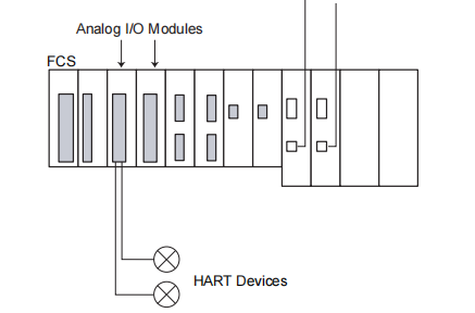
This document describes about I/O Modules with Built-in Barrier (for FIO) which can be installed in Zone 2 or
Division 2 and connected to devices located in Zone 0, 1, or Division 1.
These modules have galvanic isolation between the field interface and systems but they do not have isolation
between channels.
YOKOGAWA AFV30D-S41 I/O Modules with Built-in Barrier
These modules comply with ISA S71.04 class G3. and they can be located in the ambient temperature of -20 to 70
°C.
When connecting these modules to the intrinsically safe circuit, refer to documents “Explosion Protection” (TI
33Q01J30-01E) and “Explosion Protection of FIO Products” (IM 33K01J30-50E) for ATEX approval along with this
General Specifications (GS).
Follow the EC-type Examination Certificate or FM certification for details of the rules and regulations of installing
these modules in the intrinsically safe environment. It is especially important to follow the “Special Conditions”
stated in these certificates.
In case these I/O modules with built-in barriers are to comply with FM approval (FM3610), install them on the
following field control units (FCU) or ESB bus node units equipped with power supply modules of PW481-11.
PW482-11. or PW484-11.
Field Control Units: AFV30D-S4111. AFV30S-S3111. AFV30S-S4111
ESB Bus Node Units: ANB10D-41. ANB10S-31. ANB10S-41
ANB10D-43. ANB10S-33 , ANB10S-43
Optical ESB Bus Node Unit: ANB11D-23. ANB11D-43
ANB11S-13. ANB11S-23. ANB11S-33. ANB11S-43
Current Input Modules (Isolated)
Items Specifications
Model ASI133
Number of input channels 8. isolated
Input signal 4 to 20 mA
Allowable input current 22.5 mA
Withstanding voltage 1500 V AC
Input resistance Power ON For 2-wire: 400 Ω (I=20 mA) to 750 Ω (I=4 mA)
For 4-wire: 485 Ω (I=20 mA) to 925 Ω (I=4 mA)
Power OFF 1 MΩ or larger
Accuracy ±16 µA
Step response time 100 ms
Data update period 10 ms
Transmitter power supply 16 V DC or higher (output current limit: 20 mA)
Maximum normal mode input voltage applied to
the terminals by 4-wire transmitter 25 V
Drift due to ambient temperature change ±16 µA/10 °C
Maximum current consumption 150 mA (5 V DC), 450 mA (24 V DC)
Weight Approx. 0.30 kg
External connection Pressure clamp terminal (ATSA3□)
HART communication Available
Barrier type Isolated interface
Note: When short circuits occur in two or more channels in the field, all channels of the module fails for intrinsic safety.
l Current Output Modules (Isolated)
Items Specifications
Model ASI533
Number of output channels 8. isolated
Output signal 4 to 20 mA
Maximum output current 23 mA
Withstanding voltage 1500 V AC
Allowable load resistance 0 to 750 Ω at 20 mA, 0 to 600 Ω at 23 mA
Accuracy ±48 µA
Step response time 100 ms
Data update period 10 ms
Drift due to ambient temperature change ±16 µA/10 °C
Maximum current consumption 150 mA (5 V DC), 350 mA (24 V DC)
Weight Approx. 0.30 kg
External connection Pressure clamp terminal (ATSS3)
HART communication Available
Barrier type Isolated interface
Note: When short circuits occur in two or more channels in the field, all channels of the module fails for intrinsic safety
TC, mV Input/RTD/POT Input Modules (Isolated)
Items Specifications
Model AST143 (*1) (*2) ASR133 (*1)
Number of input channels 16. isolated 8. isolated
Input signal
TC: IEC 60584-1 (ITS-90)
Type B (*3), E, J, K, N, R, S, T
mV: -100 to 150 mV, -50 to 75 mV
RTD: 2.3 and 4-wire type
IEC 60751 (ITS-90): Pt50. Pt100. Pt200. Pt500. Pt1000
DIN 43760-1987: Ni100. Ni200
Minco: Ni120
POT: 3-wire type 0 to 10 kΩ
Switching input signal TC/mV can be set individually for CH1
to CH16. RTD/POT can be selected individually for CH1 to CH8.
Allowable input voltage ±5 V ±5 V
Withstanding voltage 1500 V AC 1500 V AC
Input resistance Power ON 1 MΩ or larger 1 MΩ or larger
Power OFF 1 MΩ or larger 1 MΩ or larger
Accuracy (at 23 °C) TC: ±40 µV
mV: ±80 µV
Pt50. Pt100. Ni100. Ni200. Ni120: ±150 mΩ
Pt200: ±300 mΩ
Pt500: ±600 mΩ
Pt1000: ±1.2 Ω
POT: ±2 Ω
Allowable total resistance of signal
source plus wiring 1000 Ω or less 50 Ω per load (*4)
Effect of allowable signal source
resistance (1000 Ω) ±20 µV –
Reference junction compensation
accuracy ±1 °C (*5) (*6) –
Measurement current – 150 µA
Temperature drift TC: ±125 µV/10 °C
mV: ±250 µV/10 °C
Pt50. Pt100. Ni100. Ni200. Ni120: ±325 mΩ/10 °C
Pt200: ±650 mΩ/10 °C
Pt500: ±1.3 Ω/10 °C
Pt1000: ±2.6 Ω/10 °C
POT: ±5.2 Ω/10 °C
Data update period 1 second or less 1 second or less
Burn-out All channels can be set together. Setting : Not available/available (UP/DOWN)
Maximum current consumption 150 mA (5 V DC), 80 mA (24 V DC) 150 mA (5 V DC), 60 mA (24 V DC)
Weight Approx. 0.30 kg Approx. 0.30 kg
External connection Pressure clamp terminal (ATST4) Pressure clamp terminal (ATSR3)
Barrier type Isolated interface Isolated interface
*1: In order to satisfy the EMC requirements in accordance with the IEC 61000. use the shielded cable. (Shielded multi-core
cable with one shield for all channel is sufficient.)
*2: Use a non-ground type thermocouple (TC) because AST143 is an isolated type module. By connecting a groun
| User name | Member Level | Quantity | Specification | Purchase Date |
|---|


- LTI Drives
- other
- ADLINK
- Beckhoff
- Shinkawa
- Other Brands
- AMAT
- Iba
- PEPPERL+FUCHS
- Aerotech
- WATLOW
- MAN
- ADVANCED
- Abaco
- YOKOGAWA
- KOLLMORGEN
- MEGGITT
- kong-sberg
- METSO
- Motorola
- NI
- OEMAX
- RELIANCE
- scanlab
- schneider
- uniop
- Vibro-Meter
- Honeywell
- Rolls-Royce
- MOOG
- GE
- B&R
- Woodward
- Yaskawa
- xYCOM
- Siemens
- Emerson
- HIMA
- Bently
- ZYGO
- FOXBORO
- OMACO
- PROSOFT
- ENTERASYS
- TRICONEX
- Parker
- Lenze
- KEBA
- Alstom
- CTI
- ABB
- A-B

-
 Woodward CPC-II Current Pressure Converter
 -
 EXOR UniOP ePALM10 Handheld HMI
 -
 TMEIC TMdrive-30/TMdrive-P30 IGBT Inverter/Converter Operation Manual
 -
 TEWS TVME200 6U VME Bus Industry Pack (IP) Carrier Board
 -
 TDK Lambda Alpha-400 (CA400) Switching Power Supply Installation Instructions
 -
 Stucke GROUP SYMAP ® Series digital protection relay
 -
 Softing CAN-AC2-PCI PCI Bus CAN Communication Interface Board
 -
 Siemens SIMATIC C7-623/C7-624 Control System
 -
 Foxboro DCS Compact 200 Series 16 Slot Horizontal Base RH916RB
 -
 Foxboro 84F/84W Intelligent Vortex Flow Meter
 -
 Foxboro E69F-BI2 on-site installation type electric pneumatic converter (I/P)
 -
 Foxboro DCS Compact200 series RH916RB (16 slot horizontal bottom plate)
 -
 Operation Instructions for Reliance Electric PSC7000 Control Card
 -
 Eaton MTL F809F Plus DTM Operating Instructions
 -
 Motorola ACE3600 series remote terminal unit RTU
 -
 MOOG D136-003-001 Rugged Motion Controller
 -
 Micro Innovation GF1 series industrial touch screen (Micro Panel)
 -
 Neles ™ NDX ™ Compact intelligent valve controller (positioner)
 -
 Jamesbury Valv‑Powr ™ Installation, maintenance, and operation of VPVL mod D actuator
 -
 Jamesbury Valv‑Powr ™ VPVL series D-type compact gear rack pneumatic actuator
 -
 GMW IPP 144-40G Embedded Thermal Printer
 -
 Meggitt C327845 flow cut-off valve
 -
 Meggitt C422425/C422685/C422695/C422705 solenoid valve
 -
 Selection of LTi Drives ServoOne Full Series Servo Drive Systems
 -
 Jenaer Antriebstechnik ECOVARIO ® Installation and Operation Instructions for 114/214/414 Servo Drivers
 -
 Honeywell TDC3000X APM Advanced Process Manager
 -
 Honeywell Notifier NFS2-3030 Intelligent Addressing Fire Alarm Controller
 -
 Honeywell EP-DOCX-SCA-SMSC-100 Universal Signal Conditioning Wiring Solution for Safety Systems (UMS)
 -
 Installation Instructions for Honeywell XL1404 Fire Alarm Controller
 -
 Honeywell Enhanced Micro TDC 3000 (MT11-520) DCS Control System
 -
 HIMA X-DI 64 01 Digital Input Module
 -
 Hirschmann MICE MS20/MS30 Industrial Switch Installation Instructions
 -
 Exor UniOP ePAD05/ePAD06 Compact HMI Industrial Human Machine Panel
 -
 Exor Effectiveness View eV058- TST/eV058- TNT Industrial Touch Screen HMI Human Machine Panel
 -
 Esd VME-PMC CADDY/2 Intelligent VME-PMC Carrier Board
 -
 Installation Instructions for Elmo Gold Tuba (G-TUB) Servo Drive
 -
 Eaton COM-MPB1-TP/COM-MPB2-TP communication module
 -
 Delta Tau Turbo PMAC2 PCI Ultralite Programmable Multi Axis Motion Controller
 -
 DATA PATTERNS DP-VME-5114 module
 -
 CMZ SVM Series Independent Two Phase Synchronous Servo Driver SVM1608 Product Specification
 -
 SUMITOMO T2100Z steel turning
 -
 SUMITOMO PSZ Turn Modular Quick Change Tool System
 -
 SUMITOMO EGU positive front corner chip breaker groove
 -
 SUMITOMO GND series slotting and cutting tools
 -
 SUMITOMO AC8000P series (AC8115P/AC8020P/AC8025P/AC8035P) steel turning
 -
 SUMITOMO AC6000M series (AC6020M/AC6030M/AC6135M/AC6145M) stainless steel turning
 -
 SUMITOMO ELECTRIC AC5000S series (AC5005S/AC5015S/AC5025S) heat-resistant alloy turning
 -
 SUMITOMO ELECTRIC AC4000K series (AC4010K/AC4015K/AC4125K) cast iron turning
 -
 SUMITOMO ELECTRIC AC1135U small lathe for turning small parts
 -
 SUMITOMO ELECTRIC AC1030U Material Blade
 -
 CCS 6900G/6900P Non Explosion proof Pressure Switch Installation and Maintenance Manual
 -
 BENDER WR70 × 175S (P)~WR200 × 500S (P) rectangular measuring current transformer
 -
 BENDER RCMA475LY B-type residual current monitor
 -
 BENDER IRDH575 A‑ISOMETER ® Insulation monitoring device
 -
 BENDER IRDH265 / IRDH365(ISOMETER ®) Insulation monitoring device
 -
 BENDER RCMA475LY AC/DC sensitive residual current monitor
 -
 Beckwith Electric M-3425A Generator Integrated Protection Relay
 -
 Automated Logic MEx816u I/O Expansion Module
 -
 ASEM HT2150 Fanless Industrial Panel X86
 -
 Advantest U3771/U3772 portable microwave millimeter wave spectrum analyzer
 -
 Advantest R6144 Programmable DC Voltage/Current Source (Calibration Source)
 -
 Aerotech UNIDEX 100/U100i single axis motion controller
 -
 Aerotech Ndrive MP Ultra Compact PWM Digital Servo Driver
 -
 Aerotech Ndrive HPe 10/20/30 High Performance PWM Digital Servo Drive
 -
 Aerotech Ndrive Linear (HLe/ML) Linear Servo Drive
 -
 Aerotech Ndrive CP Compact PWM Digital Servo Driver
 -
 Aerotech Ndrive Linear (HLe/CL/ML) linear servo drive
 -
 Aerotech Ndrive HL (EDU176 Rev1.08b) Digital Servo Drive
 -
 Aerotech Ndrive HP10/20/30 PWM Digital Servo Drive
 -
 Aerotech Ndrive series digital servo drives
 -
 SIGMATEK TAE 1941 Touch Display Unit
 -
 SIGMATEK TAE 151 Touch Display Unit
 -
 SIGMATEK AKM series servo motor
 -
 SIGMATEK S-DIAS Control System
 -
 SIGMATEK Human Machine Interface (HMI)
 -
 SIGMATEK DIAS Drive 310-23 servo amplifier
 -
 SIGMATEK CCP 521 C-DIAS processor module
 -
 MEGMEET L6 series electric drive
 -
 Sysmex XN-1000/XN-2000 Hematology Analyzer
 -
 Sysmex XN-L series (XN-530/XN-430/XN-330) fully automatic blood cell analyzer
 -
 Sysmex XN-9000 Series Fully Automated Blood Analysis Pipeline
 -
 LTI‑Motion ServoOne Field Bus Systems PROFIBUS and PROFINET
 -
 Micro Innovation MICRO PANEL GF1 Color Touch Human Computer Interface
 -
 Micro Innovation WINbloc Distributed Remote I/O System
 -
 Micro Innovation MICRO PANEL GS-2 Industrial Touch Visualization Operation Panel (HMI)
 -
 LTi LST/LSH series synchronous servo motor
 -
 LTi CDE/CDB3000 positioning controller
 -
 ENOTEC SILOTEC ® Installation and Operation Instructions for 8000 Silo Monitoring O ₂/CO ₑ Analyzer System
 -
 ENOTEC ENSITU ® 7000 Compact Oxygen Transmitter Probe
 -
 ENOTEC COMTEC ® Installation and Operation Instructions for 6000 ATEX GasEx Explosion proof O ₂/COE Analyzer System
 -
 ENOTEC Integrated Products
 -
 ENOTEC OXITEC ® 500E Extraction Oxygen Analyzer
 -
 KUKA KR CS Box-2 Compact Controller for Four Axis SCARA Robot
 -
 KUKA KR C5 slim-2 Robot Controller
 -
 KUKA KR C5 micro With KUKA System Software (KSS/VSS) Assembly Instructions
 -
 KUKA KR C5 micro controller
 -
 KUKA KR C5 Controller Assembly Instructions
 -
 KUKA KR C5 compactcab and KR C5 small-size cab cabinets
 -
 KUKA KR C4 smallsize-2 small robot control cabinet
 -
 KUKA KR C4 Midsize/KR C4 Midsize CK Assembly Manual
 -
 ENOTEC ® Installation and Operation Instructions for 5000/5000+Oxygen Analyzer System
 -
 KUKA KR C4 extended; KR C4 extended CK Assembly Instructions Assembly Manual
 -
 Assembly/Installation Manual for KUKA KR C4 Compact Control Cabinet
 -
 KUKA Sunrise Cabinet Med Medical Collaborative Robot Special Control Cabinet
 -
 KUKA Sunrise Cabinet Next Generation Small Control Cabinet
 -
 KUKA KR C4 Smallsize-2 family's smallest control cabinet
 -
 KUKA KR C4 midsize; KR C4 midsize CK medium-sized control cabinet
 -
 KUKA KR C4 extended is a high-power multi axis control cabinet
 -
 General installation and operation instructions for KUKA KR C4 and KR C4 CK controllers
 -
 KUKA KR C4 compact controller operation instructions
 -
 Installation and Operation Instructions for KUKA Robot Arm
 -
 KUKA TITAN-2 Ultra Ground Overloading Six Axis Robot
 -
 Assembly instructions for KUKA KR SCARA-2 CS series robotic arm body
 -
 KUKA MA KR SCARA X Installation Guide
 -
 KUKA KR FORTEC-2 Ultra Heavy duty Ground Six Axis Robot Mechanical Assembly Manual
 -
 KUKA KR FORTEC-2 new generation heavy-duty ground six axis robot
 -
 KUKA Robots KR 1000 titan; KR 1000 L750 titan With F Variants Assembly Instructions
 -
 KUKA KR 600 FORTEC heavy-duty six axis ground mounted industrial robot
 -
 KUKA KR 500 MT FORTEC Heavy duty Six Axis Industrial Robot
 -
 KUKA KR 360 FORTEC Heavy duty Six Axis Industrial Robot
 -
 KUKA Sunrise Cabinet Med Medical Edition Robot Controller User Manual
 -
 KUKA Robots KR SCARA HO Assembly Instructions
 -
 KUKA Robots KR QUANTEC-2 PA Assembly Instructions
 -
 KUKA Robots KR QUANTEC-2 K and KR QUANTEC-2 P With K-F and P-C Variants Assembly Instructions
 -
 KUKA Robots KR QUANTEC-2 HO Assembly Instructions
 -
 KUKA Robots KR QUANTEC-2 HC Assembly Instructions
 -
 KUKA KR QUANTEC-2 series heavy-duty ground mounted six axis industrial robot
 -
 KUKA KR QUANTEC PA series heavy-duty palletizing robot

K-JIANG

Add: Jimei North Road, Jimei District, Xiamen, Fujian, China
Tell:+86-15305925923