

K-WANG


- Telephone:+86-15305925923
- contacts:Mr.Wang
- Email:wang@kongjiangauto.com
The VersaMax IP is very robust and meets the IEC protection level IP67 (based on the IEC60529 standard). available
VersaMax IP products do not require a sealed casing in oil-water environments. Each module can be accessed through Profibus DP
The interface communicates with the Profibus DP network controlled by PLC or PC.
GE FANUC IC676PBI008 Positive logic input
Characteristics of VersaMax IP
No need to seal the casing, saving installation costs
No need for chassis and DIN rail
Each module can serve as an independent I/O station
The module communicates at a speed of 12M baud rate on the Profibus DP network
The address of the module is set by two rotary switches
The module has 8 or 16 inputs, 8 outputs, or mixed I/O (4 inputs and 4 outputs)
• Devices can be directly connected to sensors and control devices through various quick connect plugs
• Can input PNP type three wire sensor, 2-wire DC sensor or dry contact signal
• Output short circuit and overload protection
Multiple diagnostic LEDs can clearly indicate the status of power, communication, and points
general provisions
Bus power supply 18-30VDC
Internal current consumption 100mA (maximum)
Input cable length less than 100 meters
Input switching current ON 5mA
Input delay time 3.1ms
Standard NEMA4, IEC60529, IP67
Operating temperature -25 ℃ -60 ℃
Storage temperature -25 ℃ -85 ℃
Operating/Storage Humidity 95%
Wiring methods 2-, 3-, and 4-wire systems
Bus connector M12 connector head
Input connector M12 connector head
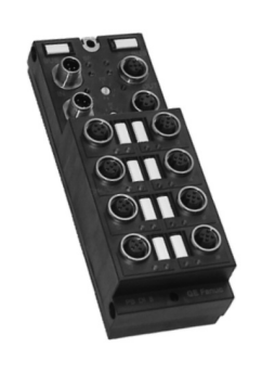
Switch input module (IP67)
The module can be directly connected to the Profibus DP bus, which provides switch inputs for connecting PNP3 line sensors.
Each input has a short-circuit protection function, with a yellow and a red LED indicating ON or overload status.
The module is encapsulated with epoxy resin and uses metal connectors, making it very sturdy.
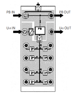
The module is connected to the Profibus DP bus through an M12 connector. One green and one red indicator light indicate the online/offline status of the module, and the module supports up to
The communication rate of the module automatically matches the communication rate of the main station at 12Mbps. The module address can be set through two rotary switches, which can be set
From 0 to 99.
The power supply is connected through a 4-pin M12 connector. The green power LED indicates that the module is powered normally.
In order to configure the module software, a GSD file is attached to the module.
Recommended cable connectors:
Profibus:IC676ACC004、IC676ACC005
Characteristics of switch input module
The input of the switch quantity is used to connect the PNP 3-wire sensor
• Input short-circuit protection function
Automatic detection of communication speed
M12 connectors are used for bus and input connections
M12 connector is used for power connection
Compliant with NEMA4, VDE0106 standards and IEC protection level IP67
• Maximum communication speed of 12 Mbps
Input module characteristics
IC676PBI008
8 inputs, DC
Supply voltage
Module power supply 18-30 VDC
Internal current consumption<100 mA (from bus power supply)
Input circuit (8) PNP 3-wire sensor
Input voltage 24 VDC standard
Input current of 5 mA per channel, short circuit protection
Input delay ON: 3.1 ms
OFF:4.1 ms
Connector
Auxiliary power supply 4-pin M12 connector
Bus M12 connector, anti loosening
Input M12 connector
set up
Address 0-99 (decimal) is controlled by two rotary switches
LED indicator
Bus green/red: normal operation/no communication
Power green/red: normal operation/bus power failure
Input status yellow: Input ON
Shell 60 x 160 x 44.5 (W x H x D)
Protection level NEMA4, IP 67
Working temperature -25 ° C to+60 ° C
Working humidity 95%
| User name | Member Level | Quantity | Specification | Purchase Date |
|---|


- LTI Drives
- other
- ADLINK
- Beckhoff
- Shinkawa
- Other Brands
- AMAT
- Iba
- PEPPERL+FUCHS
- Aerotech
- WATLOW
- MAN
- ADVANCED
- Abaco
- YOKOGAWA
- KOLLMORGEN
- MEGGITT
- kong-sberg
- METSO
- Motorola
- NI
- OEMAX
- RELIANCE
- scanlab
- schneider
- uniop
- Vibro-Meter
- Honeywell
- Rolls-Royce
- MOOG
- GE
- B&R
- Woodward
- Yaskawa
- xYCOM
- Siemens
- Emerson
- HIMA
- Bently
- ZYGO
- FOXBORO
- OMACO
- PROSOFT
- ENTERASYS
- TRICONEX
- Parker
- Lenze
- KEBA
- Alstom
- CTI
- ABB
- A-B

-
 SUMITOMO T2100Z steel turning
 -
 SUMITOMO PSZ Turn Modular Quick Change Tool System
 -
 SUMITOMO EGU positive front corner chip breaker groove
 -
 SUMITOMO GND series slotting and cutting tools
 -
 SUMITOMO AC8000P series (AC8115P/AC8020P/AC8025P/AC8035P) steel turning
 -
 SUMITOMO AC6000M series (AC6020M/AC6030M/AC6135M/AC6145M) stainless steel turning
 -
 SUMITOMO ELECTRIC AC5000S series (AC5005S/AC5015S/AC5025S) heat-resistant alloy turning
 -
 SUMITOMO ELECTRIC AC4000K series (AC4010K/AC4015K/AC4125K) cast iron turning
 -
 SUMITOMO ELECTRIC AC1135U small lathe for turning small parts
 -
 SUMITOMO ELECTRIC AC1030U Material Blade
 -
 CCS 6900G/6900P Non Explosion proof Pressure Switch Installation and Maintenance Manual
 -
 BENDER WR70 × 175S (P)~WR200 × 500S (P) rectangular measuring current transformer
 -
 BENDER RCMA475LY B-type residual current monitor
 -
 BENDER IRDH575 A‑ISOMETER ® Insulation monitoring device
 -
 BENDER IRDH265 / IRDH365(ISOMETER ®) Insulation monitoring device
 -
 BENDER RCMA475LY AC/DC sensitive residual current monitor
 -
 Beckwith Electric M-3425A Generator Integrated Protection Relay
 -
 Automated Logic MEx816u I/O Expansion Module
 -
 ASEM HT2150 Fanless Industrial Panel X86
 -
 Advantest U3771/U3772 portable microwave millimeter wave spectrum analyzer
 -
 Advantest R6144 Programmable DC Voltage/Current Source (Calibration Source)
 -
 Aerotech UNIDEX 100/U100i single axis motion controller
 -
 Aerotech Ndrive MP Ultra Compact PWM Digital Servo Driver
 -
 Aerotech Ndrive HPe 10/20/30 High Performance PWM Digital Servo Drive
 -
 Aerotech Ndrive Linear (HLe/ML) Linear Servo Drive
 -
 Aerotech Ndrive CP Compact PWM Digital Servo Driver
 -
 Aerotech Ndrive Linear (HLe/CL/ML) linear servo drive
 -
 Aerotech Ndrive HL (EDU176 Rev1.08b) Digital Servo Drive
 -
 Aerotech Ndrive HP10/20/30 PWM Digital Servo Drive
 -
 Aerotech Ndrive series digital servo drives
 -
 SIGMATEK TAE 1941 Touch Display Unit
 -
 SIGMATEK TAE 151 Touch Display Unit
 -
 SIGMATEK AKM series servo motor
 -
 SIGMATEK S-DIAS Control System
 -
 SIGMATEK Human Machine Interface (HMI)
 -
 SIGMATEK DIAS Drive 310-23 servo amplifier
 -
 SIGMATEK CCP 521 C-DIAS processor module
 -
 MEGMEET L6 series electric drive
 -
 Sysmex XN-1000/XN-2000 Hematology Analyzer
 -
 Sysmex XN-L series (XN-530/XN-430/XN-330) fully automatic blood cell analyzer
 -
 Sysmex XN-9000 Series Fully Automated Blood Analysis Pipeline
 -
 LTI‑Motion ServoOne Field Bus Systems PROFIBUS and PROFINET
 -
 Micro Innovation MICRO PANEL GF1 Color Touch Human Computer Interface
 -
 Micro Innovation WINbloc Distributed Remote I/O System
 -
 Micro Innovation MICRO PANEL GS-2 Industrial Touch Visualization Operation Panel (HMI)
 -
 LTi LST/LSH series synchronous servo motor
 -
 LTi CDE/CDB3000 positioning controller
 -
 ENOTEC SILOTEC ® Installation and Operation Instructions for 8000 Silo Monitoring O ₂/CO ₑ Analyzer System
 -
 ENOTEC ENSITU ® 7000 Compact Oxygen Transmitter Probe
 -
 ENOTEC COMTEC ® Installation and Operation Instructions for 6000 ATEX GasEx Explosion proof O ₂/COE Analyzer System
 -
 ENOTEC Integrated Products
 -
 ENOTEC OXITEC ® 500E Extraction Oxygen Analyzer
 -
 KUKA KR CS Box-2 Compact Controller for Four Axis SCARA Robot
 -
 KUKA KR C5 slim-2 Robot Controller
 -
 KUKA KR C5 micro With KUKA System Software (KSS/VSS) Assembly Instructions
 -
 KUKA KR C5 micro controller
 -
 KUKA KR C5 Controller Assembly Instructions
 -
 KUKA KR C5 compactcab and KR C5 small-size cab cabinets
 -
 KUKA KR C4 smallsize-2 small robot control cabinet
 -
 KUKA KR C4 Midsize/KR C4 Midsize CK Assembly Manual
 -
 ENOTEC ® Installation and Operation Instructions for 5000/5000+Oxygen Analyzer System
 -
 KUKA KR C4 extended; KR C4 extended CK Assembly Instructions Assembly Manual
 -
 Assembly/Installation Manual for KUKA KR C4 Compact Control Cabinet
 -
 KUKA Sunrise Cabinet Med Medical Collaborative Robot Special Control Cabinet
 -
 KUKA Sunrise Cabinet Next Generation Small Control Cabinet
 -
 KUKA KR C4 Smallsize-2 family's smallest control cabinet
 -
 KUKA KR C4 midsize; KR C4 midsize CK medium-sized control cabinet
 -
 KUKA KR C4 extended is a high-power multi axis control cabinet
 -
 General installation and operation instructions for KUKA KR C4 and KR C4 CK controllers
 -
 KUKA KR C4 compact controller operation instructions
 -
 Installation and Operation Instructions for KUKA Robot Arm
 -
 KUKA TITAN-2 Ultra Ground Overloading Six Axis Robot
 -
 Assembly instructions for KUKA KR SCARA-2 CS series robotic arm body
 -
 KUKA MA KR SCARA X Installation Guide
 -
 KUKA KR FORTEC-2 Ultra Heavy duty Ground Six Axis Robot Mechanical Assembly Manual
 -
 KUKA KR FORTEC-2 new generation heavy-duty ground six axis robot
 -
 KUKA Robots KR 1000 titan; KR 1000 L750 titan With F Variants Assembly Instructions
 -
 KUKA KR 600 FORTEC heavy-duty six axis ground mounted industrial robot
 -
 KUKA KR 500 MT FORTEC Heavy duty Six Axis Industrial Robot
 -
 KUKA KR 360 FORTEC Heavy duty Six Axis Industrial Robot
 -
 KUKA Sunrise Cabinet Med Medical Edition Robot Controller User Manual
 -
 KUKA Robots KR SCARA HO Assembly Instructions
 -
 KUKA Robots KR QUANTEC-2 PA Assembly Instructions
 -
 KUKA Robots KR QUANTEC-2 K and KR QUANTEC-2 P With K-F and P-C Variants Assembly Instructions
 -
 KUKA Robots KR QUANTEC-2 HO Assembly Instructions
 -
 KUKA Robots KR QUANTEC-2 HC Assembly Instructions
 -
 KUKA KR QUANTEC-2 series heavy-duty ground mounted six axis industrial robot
 -
 KUKA KR QUANTEC PA series heavy-duty palletizing robot
 -
 KUKA KR IONTEC-2 series six axis industrial robot
 -
 KUKA KR IONTEC ultra series six axis heavy-duty industrial robot
 -
 KUKA KR IONTEC HO Robot Assembly Manual
 -
 KUKA Robots KR CYBERTECH-3 HW Assembly Instructions
 -
 KUKA Robots KR CYBERTECH-3 Assembly Instructions
 -
 KUKA Robots KR CYBERTECH-2 arc Assembly Instructions
 -
 KUKA Robots KR CYBERTECH nano-2 Assembly Instructions
 -
 KUKA KR CYBERTECH CR HO (KR 20 R1810-HO) assembly instructions
 -
 KUKA Robots KR CYBERTECH With F variant Assembly Instructions
 -
 KUKA KR CYBERTECH CR (KR 20 R1810-CR) Clean Room (CR) Version 6-Axis Industrial Robot
 -
 KUKA KR AGILUS-3 ultra series small six axis serial robot
 -
 KUKA KR 300 R2700-2 C-F Cast Ceiling Mounted 6-Axis Heavy duty Industrial Robot
 -
 KUKA KR 20 R1820-2 E Six Axis Industrial Robot
 -
 Assembly instructions for KUKA KR AGILUS-3 small six axis robot
 -
 KUKA KR AGILUS-2 New Generation Small Six Axis Robot
 -
 KUKA KR 1000 1300 titan PA; KR 1000 L950 titan PA With F Variants Assembly Instructions
 -
 KUKA KR 700 PA/KR 700 PA Arctic Installation Guide
 -
 KUKA KR 18 R1450-3 PP six axis ground mounted industrial robot
 -
 KUKA 12 SCARA Series 4-axis SCARA Horizontal Joint Robot
 -
 KUKA KR 4 R600 Small Six Axis Industrial Robot
 -
 Installation Guide for KUKA KR 3 R540 Small 6-Axis Industrial Robot
 -
 KUKA LBR iiwa CR Clean 7-Axis Lightweight Collaborative Robot
 -
 KUKA KR AGILUS sixx series six axis industrial robot operation instructions
 -
 KUKA 4-axis heavy-duty SCARA horizontal multi joint robot KR 60 R1200 Z400 CS
 -
 KUKA KR 23 SCARA-2 CS SCARA Horizontal Multi Joint Robot
 -
 KUKA KR 20 SCARA CS Robot Assembly Instructions
 -
 KUKA KR 15 DELTA-2 Assembly Manual
 -
 KUKA KR 13 SCARA-2 CS Assembly Manual
 -
 KUKA KR 3 D1200 (Standard Delta Robot) Assembly Instructions
 -
 KUKA KR 3 D1200 HM Assembly Manual
 -
 KUKA LBR Med 7 R800, LBR Med 14 R820 Medical Edition Robot
 -
 KUKA Robots LBR iiwa 7 R800, LBR iiwa 14 R820 Operating instructions
 -
 KUKA LBR iiwa CR (Clean Room Version Robot) Operating Instructions
 -
 Lauer PCStopline series text operation panel
 -
 KUKA LBR iisy (MA_LBR_iisy V5) assembly manual
 -
 KUKA LBR iisy 3 R760 Assembly Manual
 -
 KUKA LBR iico Collaborative Robot Assembly Manual
 -
 Lauer LCAstarline (LCA300/LCA320/LCA325) Text Display Screen
 -
 Lauer PCS950/PCS950c/PCS950e operation console
 -
 Lauer EPC Series Industrial Embedded Human Computer Integrated PC User Guide

K-JIANG

Add: Jimei North Road, Jimei District, Xiamen, Fujian, China
Tell:+86-15305925923