
K-WANG
+086-15305925923
Service expert in industrial control field!


Product
Article
NameDescriptionContent
Adequate Inventory, Timely Service
pursuit of excellence


Ship control system
Equipment control system
Power monitoring system
Brand
Product parameters
- Telephone:+86-15305925923
- contacts:Mr.Wang
- Email:wang@kongjiangauto.com
Description
This publication describes the installation, operation, and maintenance of the Honeywell HC900 Process Controller. This publication includes the following sections.
Honeywell Digital Input, 24VDC (32 channel)900G32-0101
Chapter Title Page Content
Introduction 1 Model numbers, how to verify component compatibility, function description of
components, feature summary.
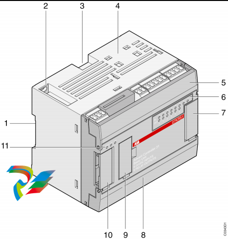
Components and
Architecture
17 Functional features and physical characteristics of the system and of each major
component of the HC900 Process Controller. Networking components and
methods of interconnection.
Pre-Installation
Planning
44 Pre-planning considerations and procedural guidelines for planning an installation.
Rack Installation 65 Procedures for installing the major components of the system: controller rack, I/O
expansion racks, and communication interconnections.
I/O Module
Installation and
Wiring
78 Procedures for installing I/O modules in the controller rack and I/O expansion
racks, and for wiring field devices to the terminal block associated with each
I/O module.
Communications
Installation
127 Guidelines for installing RS-232, RS-485 to USB cable, RS-485, and Ethernet
cabling and associated components.
Operating
Characteristics
155 Characteristics of the HC900 Process Controller as they relate to configuration of
a control strategy, and to operation of an installed and running system.
Redundant
Operating
Characteristics
165 Characteristics of redundant operation.
Diagnostics and
Troubleshooting
173 Mechanisms that detect and react to faults in the operation of HC900 Process
Controller hardware and/or software components.
Analog Calibration 191 Hardware configuration required for calibrating AI and AO modules from the
configuration software.
Removal and
Replacement
Procedures
196 Guidelines for replacing system components; includes Cautions and Warnings as
applicable.
Specifications 206 Details of HC900 Process Controller design and functioning.
Appendix -
Installation of
Remote
Termination Panels
(RTPs)
217 The Remote Termination Panel (RTP) provides an easy way to connect the
HC900 controller to the field wiring. The RTP integrates some of the typical
externally connected components, reducing wiring and setup time. It also
minimizes the need for multiple wires under a single screw connection by
expanding the connectivity of the shared terminals of the I/O modules.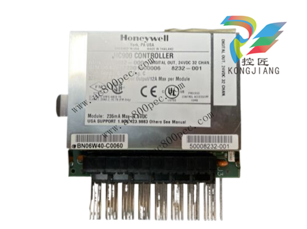
Model Selection Guide
Legacy System
Description Model number SIL Compatible*
Racks
4 I/O Slot Rack 900R04 – 0001 No
8 I/O Slot Rack 900R08 – 0101 No
12 I/O Slot Rack 900R12 – 0101 No
8 Slot Rack -Red. Power 900R08R – 0101 No
12 Slot Rack - Red. Power 900R12R – 0101 No
Redundant CPU Rack 900RR0 – 0001 No
Controllers
Controller C50 CPU 900C52 – 02XX-00 No
Controller C30 CPU 900C32 – 02XX-00 No
Controller C70 CPU 900C72 – 01XX-00 No
Controller C70R CPU 900C72R – 01XX-44 No
Redundancy switch module 900RSM – 0001 No
I/O Scanner - 2 Port (1 per I/O rack) 900C73R – 01XX-44 No
I/O Scanner (for remote rack) 900C53 – 02XX-00 No
Redundant Power Status Module 900PSM – 0001 No
Power Supplies
120/240VAC, 60W 900P01 – 0001 No
120/240VAC, 28W 900P02 – 0001 No
+24VDC 900P24 – 0001 NA
I/O Modules
Analog Input (8 channel) 900A01 – 0102 No
High Level Analog Input (16 channel) 900A16 – 0001 No
Analog Output, 0 to 20mA, (4 channel) 900B01 – 0201 No
Analog Output, 0 to 20mA, (8 channel) 900B08 – 0001 No
Analog Output, 0 to 20mA, (16 channel) 900B16 – 0001 No
Digital Input, Contact type, (16 channel) 900G01 – 0102 No
Digital Input, 24VDC (16 channel) 900G02 – 0102 No
Digital Input, 24VDC (32 channel) 900G32 – 0001 No
Digital Input, 120/240 VAC, (16 channel) 900G03 – 0102 No
Digital Input, 120/240VAC, 125VDC (16ch-Iso) 900G04 – 0001 No
Digital Output, Relays ( 8 channel) 900H01 – 0102 No
Digital Output, 24VDC (16 channel) 900H02 – 0102 No
Digital Output, 24VDC (32 channel) 900H32 – 0001 No
Digital Output, 120/240 VAC (8 channel) 900H03 – 0102 No
Pulse/Frequency/Quadrature 900K01 – 0101 N
Description Model number SIL Compatible*
I/O Components
Low VoltageTerminal Block (Euro style) 900TEK – 0001 No
Low VoltageTerminal Block (Barrier Style) 900TBK – 0001 No
High VoltageTerminal Block (Euro style) 900TER – 0001 No
High Voltage Terminal Block (Barrier Style) 900TBR – 0001 No
High Density Terminal Block 900TCK – 0001 No
I/O Components
Analog Input Remote Terminal Panel (RTP) 900RTA – L001 NA
Relay Output Remote Terminal Panel (RTP) 900RTR – H001 NA
DI, DO, AO Remote Terminal Panel (RTP) 900RTS – 0001 NA
Low Voltage RTP Cable (1.0M, 3.28ft.) 900RTC – L010 NA
Low Voltage RTP Cable (2.5M, 8.2ft.) 900RTC – L025 NA
Low Voltage RTP Cable (5.0M, 16.4ft.) 900RTC – L050 NA
High Voltage RTP Cable (1.0M, 3.28ft.) 900RTC – H010 NA
High Voltage RTP Cable (2.5M, 8.2ft.) 900RTC – H025 NA
High Voltage RTP Cable (5.0M, 16.4ft.) 900RTC – H050 NA
High Density RTP Cable (1.0M, 3.28ft.) 900RTC – 3210 NA
High Density RTP Cable (2.5M, 8.2ft.) 900RTC – 3225 NA
High Density RTP Cable (5M, 16.4ft.) 900RTC-3250 NA
Filler Block Terminal Cover 900TNF – 0001 NA
Shield Terminal Strip (package of 2) 900TSS – 0001 NA
Terminal board jumpers (10, two pos jumpers) 900J02 – 0001 No
Terminal board jumpers (10, ten pos.jumpers) 900J10 – 0001 No
Manuals
Full Document set on CD 900ME1 – 00XX-XX NA
Software
HC Designer Config. Software CD 900W01 – 00XX-XX NA
HC Utilities Software/Documentation CD 900W02 – 00XX-XX NA
Kits & Accessories
Redundant Power, Rack Extension Kit 900RPE – 0001 NA
Spare I/O Label Kit 51452262 – 501 NA
Replacement Battery Kit 51500638 – 501 NA
Ethernet Cable (10 feet) 51451432 – 010 NA
Ethernet Cable (20 feet) 51451432 – 020 NA
Ethernet Cross-over Cable (20 feet) 51451996 – 020 NA
Null Modem Cable 51404755 – 501 NA
Null Modem Cable used with 900C70R 50004820 – 501 NA
250 ohm Shunt Resistor Kit ( (8/pkg.) 51205995 – 501 NA
Ethernet Switching Hub (8 Ports) 50008930 – 001 NA
24 VDC Power Supply 51452041 – 501 NA
Purchase history
| User name | Member Level | Quantity | Specification | Purchase Date |
|---|
Total 0 Record
Related products
Customer Reviews
Satisfaction :
5 Stars
No evaluation information


- other
- LTI Drives
- ADLINK
- Beckhoff
- Other Brands
- AMAT
- Iba
- PEPPERL+FUCHS
- Aerotech
- WATLOW
- MAN
- ADVANCED
- Abaco
- YOKOGAWA
- KOLLMORGEN
- MEGGITT
- kong-sberg
- METSO
- Motorola
- NI
- OEMAX
- RELIANCE
- scanlab
- schneider
- uniop
- Vibro-Meter
- Honeywell
- Rolls-Royce
- MOOG
- GE
- B&R
- Woodward
- Yaskawa
- xYCOM
- Siemens
- Emerson
- HIMA
- Bently
- ZYGO
- FOXBORO
- OMACO
- PROSOFT
- ENTERASYS
- TRICONEX
- Parker
- Lenze
- KEBA
- Alstom
- CTI
- ABB
- A-B
142

-
 ADLINK AmITX-ALN-N97 Mini ITX Industrial Motherboard
 -
 ADLINK NuPRO-850 Full length ePCI-X Industrial Control Board
 -
 ADLINK MI-965 Mini ITX Industrial Motherboard
 -
 ADLINK M-302 ATX Industrial Motherboard
 -
 ADLINK PXI-3920/PXI-3910 3U PXI System Controller
 -
 ADLINK PCI-8132 Two Axis Servo/Stepper Motion Control Card
 -
 ADLINK cPCI-6760D 6U CompactPCI Single Board Computer
 -
 ADLINK ACL-7122 144 bit digital I/O board
 -
 ADLINK NuPRO-775 Half length Socket370 Industrial Single Board Computer
 -
 ETEL Accuret MODULAR series servo controller
 -
 ADLINK PCI-9112/cPCI-9112 multifunctional acquisition card
 -
 ADLINK PCI-8102 Two Axis Pulse Motion Control Card
 -
 ADLINK PCI-9812/PCI-9810 synchronous 4-channel high-speed acquisition card
 -
 ADLINK PCI-7200/cPCI-7200 high-speed digital I/O board
 -
 ADLINK MXE-1000 series fanless embedded machine
 -
 ADLINK IMB-T10 Mini ITX Industrial Motherboard
 -
 ADLINK HSL Distributed High Speed I/O System
 -
 ADLINK PXI/DAQ/DAQe-2500 series multifunctional analog output DAQ card
 -
 ADLINK PXI/DAQ/DAQe-2200 series multifunctional data acquisition card
 -
 ADLINK ETX-AT ETX Core Computer Module
 -
 ADLINK ACL-7225 ISA 16 channel relay output+16 channel isolated digital input card
 -
 ADLINK DAQ-2000 series synchronous acquisition card
 -
 ADLINK NuPRO-E330 PICMG 1.3 full-length industrial motherboard (SHB)
 -
 ADLINK ACL-8112 series multifunctional ISA acquisition card
 -
 ADLINK USB-2405 24 bit dynamic signal acquisition module
 -
 ADLINK PXIS-3320 15 slot 6U PXI chassis
 -
 ADLINK PCIe GIE7x series acquisition card
 -
 ADLINK PCIe-7856/PCIe-7853 Distributed Motion and IO Main Controller PCIe Acquisition Card
 -
 ADLINK PCI-6308 series isolated analog output board
 -
 ADLINK PCI-7432 Isolated Digital I/O Acquisition Card
 -
 ADLINK NuPRO-E72 PICMG 1.3 Full length Industrial SHB Single Board Computer
 -
 ADLINK MXE-5400 series fanless embedded industrial computer
 -
 ADLINK M-322 Industrial ATX Motherboard
 -
 ADLINK IMB-M43H Industrial ATX Motherboard
 -
 ADLINK IMB-M42H Industrial ATX Motherboard
 -
 ADLINK i915GV-INA ATX motherboard
 -
 ADLINK ETX-NR667 Embedded ETX Standard Computer Module
 -
 ADLINK ETX-BT (PATA to SATA version) User Manual
 -
 ADLINK CM1-BT1 PC/104 Single Board Computer
 -
![ADLINK cPCI-8217 [R] 3U CompactPCI VGA/LCD Display Module](https://aosspic10001.websiteonline.cn/hkw632bc8/image/image_aJXQRn.png) ADLINK cPCI-8217 [R] 3U CompactPCI VGA/LCD Display Module
ADLINK cPCI-8217 [R] 3U CompactPCI VGA/LCD Display Module -
 ADLINK AmITX-SL-G Mini ITX Embedded Motherboard
 -
 ADLINK AmITX-AL-I ultra-thin Mini ITX industrial motherboard
 -
 ADLINK NuPRO-E315 Full length PICMG 1.3 Industrial SHB Single Board Computer
 -
 ADLINK NuPRO-842 Full length PICMG 1.0 PCI/ISA Industrial Single Board Computer
 -
 ADLINK NuPRO-900A PICMG 1.2 ePCI-X Dual Xeon Industrial System Motherboard (SHB)
 -
 ADLINK cPCI-6910 series 6U CompactPCI single board computer
 -
 ADLINK cPCI-6860A 6U CompactPCI dual core single board computer with cPCI-R6860A rear adapter board
 -
 ADLINK cPCI-8168 6U CompactPCI Eight Axis Motion Control Card
 -
 ADLINK NuPRO-E340 PICMG 1.3 Industrial SHB motherboard
 -
 ADLINK NuPRO-A40H Full length PICMG1.0 Industrial Single Board Computer (SBC)
 -
 ADLINK NuPRO-852 Full length PICMG1.0 Industrial Single Board Computer
 -
 ADLINK NuPRO-841 Full length Industrial SBC
 -
 ADLINK NuPRO-590/591/592 series Socket7 full-length industrial SBC
 -
 ADLINK MXE-5500 series fanless embedded industrial computer
 -
 ADLINK MXE-200/200i Fanless Embedded Machine
 -
 ADLINK cPCI-6770 series CompactPCI CPU board
 -
 ADLINK NuPRO-A301 standard PICMG 1.0 full-length industrial SBC single board computer
 -
 ADLINK NuPRO-965 PICMG 1.3 SHB Express Full length Industrial Motherboard
 -
 ADLINK NuPRO-935A Full length PICMG1.0 Industrial Single Board Computer
 -
 ADLINK NuPRO-865 Full length Single Board Computer
 -
 ADLINK NuPRO-840 DV/LV Full Length PICMG Industrial Single Board Computer
 -
 ADLINK NuPRO-770 series full-length industrial single board computer
 -
 ADLINK NuPRO-595 series half length Socket 7 industrial motherboard
 -
 ADLINK cPCI-6840 series 6U CompactPCI single board computer
 -
 Foxboro 43AP series pneumatic indicator controller (PSS 3-1B3 A)
 -
 ADLINK cPCI-3720 Series 3U Low Power CompactPCI Single Board Computer
 -
 ADLINK NuPRO-E47, PICMG 1.3 full-length industrial SHB system motherboard
 -
 ADLINK NuPRO-E43 PICMG 1.3 full-length system motherboard
 -
 ADLINK NuPRO-780 series full-length industrial CPU board
 -
 ADLINK cPCI-6965 series 6U CPCI single board computer
 -
 ADLINK USB/LPCI/LPCIe-3488A GPIB interface card
 -
 Rittal SK 3241.700 Blue e+Fan Filter Unit
 -
 ADLINK cPCI-8168 6U CompactPCI 8-Axis Motion Control Card
 -
 ADLINK PCIe PXIe-8638 PCIe to PXIe Bus Expansion Kit
 -
 ADLINK PCIe GIE7x series acquisition card
 -
 ADLINK PCIe-7396 96 96 channel TTL digital IO card
 -
 ADLINK PCI/MPC/PXI-8164 Three in One Motion Control Card
 -
 ADLINK PCI-8154 Four Axis Pulse Motion Control Card
 -
 ADLINK PCI-8134 Four Axis Servo/Stepper Motion Control Card
 -
 ADLINK NuPRO-E42 PICMG1.3 full-length SHB motherboard
 -
 ADLINK MXC-6600 series high-performance fanless extended industrial computer
 -
 ADLINK MXC-6000 series embedded industrial control computer
 -
 ADLINK MXC-2300 series fanless expandable embedded industrial computer
 -
 ADLINK MCM-204 Independent Ethernet DAQ User Manual
 -
 ADLINK MCM-100/102 Edge IoT Platform for Machine Condition Monitoring User’s Manual
 -
 ADLINK MXC-6400 series sixth generation Core Fanless Scalable Industrial Control Computer
 -
 ADLINK Matrix Full Series Fanless Embedded Industrial Control Computers
 -
 ADLINK GIE64+4-channel PoE Gigabit Vision Capture Card
 -
 Honeywell UMS Security System Troubleshooting Guide
 -
 Honeywell Expert Series-C I/O Module
 -
 ADLINK EOS-1200 Embedded Vision Host
 -
 ADLINK DLAP-5200 series high-performance fanless AI industrial computer
 -
 ADLINK DLAP-4000 series embedded industrial control computer
 -
 ADLINK Matrix MXC-2000 Series Fanless Industrial Control Computer Specification
 -
 ADLINK DAQ -/DAQE -/PXI-2000 Series Multi functional Synchronous Acquisition Card
 -
 ADLINK cPCI-6520 6U CompactPCI Single Board Computer
 -
 ADLINK CM1-86DX3 PC/104 Single Board Computer
 -
 Honeywell DC1000 series PID temperature controller
 -
 ALSTOM MiCOM C264 Modular Substation Controller
 -
 EMERSON AMS 2140 Mechanical Health Analyzer
 -
 ADLINK NuPRO-E320 PICMG1.3 Full length Industrial Motherboard
 -
 ADLINK NuPRO-800 Series Full length Industrial SBC User Manual
 -
 ADLINK NuPRO-598 Industrial Single Board Computer
 -
 ADLINK MXC-6300 Fanless Embedded Industrial Control Computer
 -
 ADLINK Express-BASE7 User Manual
 -
 ADLINK DLAP-211 Series Fanless Edge AI Platform Specification Manual
 -
 ADLINK PCI/LPCI/LPCIe/cPCI-723X series 32 channel isolated digital I/O card
 -
 ADLINK cPCI-6965 series 6U CompactPCI single board computer
 -
 ADLINK NuDAQ 7200 series high-speed digital I/O board
 -
 Linghua ADLINK DLAP Deep Learning Acceleration Platform Product Manual
 -
 DEIF TCM-2 thyristor control module
 -
 Installation Manual for DEIF MVR-200 Series Medium Voltage Protection Device
 -
 DEIF MDR-2 multifunctional differential relay
 -
 DEIF AOM-1 Analog Output Module
 -
 DEIF AGI 400 series industrial/marine touch screen
 -
 Installation Manual for DEIF BRW-1 Marine Wing Bridge Instrument
 -
 DEIF AGC200 Quick Start Guide
 -
 DEIF AGC Multi line 2 Generator Set ControllerProduct basic information
 -
 ABB SPA-ZC 400 Ethernet Gateway Installation and Debugging Manual
 -
 ABB REM 543/545 motor generator protection device
 -
 DEIF PPU 300 controller
 -
 DEIF Delomatic 4 Offshore/Ocean Platform Dedicated Generator Power Management System DM-4
 -
 DEIF Delomatic Modular Generator Set Integrated System
 -
 DEIF AGC-4 Mk II Generator Set Controller
 -
 DEIF AGC-4 diesel generator set integrated controller
 -
 DEIF Multi line 2 Series PPU Unit Power Management (PPM) Operation Manual
 -
 DEIF Multi line 2 V2.4X Installation Manual
 -
 Beckwith M-6280 Digital Capacitor Bank Controller

K-JIANG

Add: Jimei North Road, Jimei District, Xiamen, Fujian, China
Tell:+86-15305925923