

K-WANG


- Telephone:+86-15305925923
- contacts:Mr.Wang
- Email:wang@kongjiangauto.com
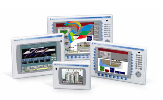
Move your platform applications into the future with the new Allen-Bradley PanelView Plus from Rockwell Automation. PanelView Plus is ideal for applications with a need to monitor, control, and display information graphically, allowing operators to quickly understand the status of their application. A cornerstone of the ViewAnyWare strategy, PanelView Plus is programmed with RSView Studio Machine Edition. It combines the best features from the popular Allen-Bradley PanelView Standard and PanelView “e” operator interface products and adds new functionality
Allen-Bradley-2711P-RDT12HHuman computer interactive touch screen
With a new and innovative modular design, the PanelView Plus is a flexible, affordable terminal enabling OEMs, system integrators, and end users to select, modify, or upgrade components to meet changing application requirements. The memory, display, communication module, and front bezel can be installed with minimal effort using a simple screwdriver. Your investment in PanelView products is protected with the ability to import existing PanelView Standard and PanelView “e” applications into RSView Studio. In addition, the PanelView Plus is designed to fit into current PanelView cutouts, so there is no need to modify your panel design. Whether it is providing more functionality, reducing development time, or simplifying future maintenance, PanelView Plus saves time and money.
Advantages • High environmental specifications • RSView ME advanced functionality • Flexible communication options • Modular design for flexibility, inventory reduction, and easy upgrades • 6.5”, 10.4”, 12.1”, and 15” TFT active matrix color displays with keypad, touch, and keypad/touch versions • Unit level immediate exchange program • Complete package for immediate startup • Global sales and support
Both ultraviolet and infrared radiation can reduce the field life of any electronic device. While the materials used in the PanelView Plus and VersaView CE bezels provide long field life, that life can be improved by proper installation. Ultraviolet radiation from the sun causes all plastics to fade or yellow and become brittle over time. Using an antiglare overlay, cat. no. 2711P-RGT12. will protect the front of the terminal from direct exposure to UV radiation and greatly increase its field life. When installing the High-Bright display module in an environment where the front of the terminal will be in direct sunlight during the hottest part of the day and the external ambient temperature can exceed 40 °C (104 °F), use the visor kit, cat. no. 2711P-RVT12. The visor reduces the solar load on the front of the display and helps to maintain internal temperatures within specification. The High-Bright display module has a built in temperature sensor that automatically reduces the backlight intensity if the temperature inside the cabinet exceeds 55 °C. This reduces the risk of damage to the display. The paint color, size, and power dissipated by the internal components of an enclosure affect the temperature rise inside the cabinet. Hoffman, a Rockwell Automation Encompass Partner, has information to assist you with enclosure selection and heating/cooling accessories to meet the temperature requirements of the installed equipment. See website http://www.hoffmanonline.com. Stirring fans or active cooling may be required in high altitude and high ambient temperature locations to keep the internal enclosure temperature below 55 °C (131 °F). Use a heater in installations where the ambient temperature is below 0 °C (32 °F). The backlight of the High-Bright display generates a significant amount of heat when set to full intensity. To minimize the amount of heat generated and extend the life of the backlight, decrease the display intensity by using the screen saver with a 5 to 10 minute delay. Avoid placing the terminal on the south (north in the southern hemisphere) or west side of the cabinet, if possible. This will reduce the heat rise due to solar loading during the hottest part of the day. Mount the terminal vertically to minimize solar loading on the display. Do not mount the terminal in a sloped enclosure if it will be exposed to direct sunlight
Mounting Clearances Allow adequate clearance around the terminal, inside the enclosure, for adequate ventilation. Consider heat produced by other devices in the enclosure. The ambient temperature around the terminals must be between 0 to 55 °C (32 to 131 °F). Minimum clearances for ventilation are: • Top clearance: 51 mm (2 in) • Bottom clearance: 102 mm (4 in) • Side clearances: 25 mm (1 in) • Back clearance: 25 mm (1 in) Minimum side clearance for insertion of memory card is 102 mm (4 in). Panel Cutout Dimensions The table lists the panel cutout dimensions for the terminal. Use the full size template shipped with your terminal to mark the cutout dimensions. Mount the Terminal in a Panel Four mounting clips secure the terminal to the panel. 1. Cut an opening in the panel using the panel cutout shipped with the terminal. 2. Make sure the terminal sealing gasket is properly positioned on the terminal. PanelView Plus and VersaView CE Terminals Height mm (in) Width mm (in) 1250/1250H Touch 257 (10.11) 338 (13.29)
| User name | Member Level | Quantity | Specification | Purchase Date |
|---|


- LTI Drives
- other
- ADLINK
- Beckhoff
- Shinkawa
- Other Brands
- AMAT
- Iba
- PEPPERL+FUCHS
- Aerotech
- WATLOW
- MAN
- ADVANCED
- Abaco
- YOKOGAWA
- KOLLMORGEN
- MEGGITT
- kong-sberg
- METSO
- Motorola
- NI
- OEMAX
- RELIANCE
- scanlab
- schneider
- uniop
- Vibro-Meter
- Honeywell
- Rolls-Royce
- MOOG
- GE
- B&R
- Woodward
- Yaskawa
- xYCOM
- Siemens
- Emerson
- HIMA
- Bently
- ZYGO
- FOXBORO
- OMACO
- PROSOFT
- ENTERASYS
- TRICONEX
- Parker
- Lenze
- KEBA
- Alstom
- CTI
- ABB
- A-B

-
 SUMITOMO T2100Z steel turning
 -
 SUMITOMO PSZ Turn Modular Quick Change Tool System
 -
 SUMITOMO EGU positive front corner chip breaker groove
 -
 SUMITOMO GND series slotting and cutting tools
 -
 SUMITOMO AC8000P series (AC8115P/AC8020P/AC8025P/AC8035P) steel turning
 -
 SUMITOMO AC6000M series (AC6020M/AC6030M/AC6135M/AC6145M) stainless steel turning
 -
 SUMITOMO ELECTRIC AC5000S series (AC5005S/AC5015S/AC5025S) heat-resistant alloy turning
 -
 SUMITOMO ELECTRIC AC4000K series (AC4010K/AC4015K/AC4125K) cast iron turning
 -
 SUMITOMO ELECTRIC AC1135U small lathe for turning small parts
 -
 SUMITOMO ELECTRIC AC1030U Material Blade
 -
 CCS 6900G/6900P Non Explosion proof Pressure Switch Installation and Maintenance Manual
 -
 BENDER WR70 × 175S (P)~WR200 × 500S (P) rectangular measuring current transformer
 -
 BENDER RCMA475LY B-type residual current monitor
 -
 BENDER IRDH575 A‑ISOMETER ® Insulation monitoring device
 -
 BENDER IRDH265 / IRDH365(ISOMETER ®) Insulation monitoring device
 -
 BENDER RCMA475LY AC/DC sensitive residual current monitor
 -
 Beckwith Electric M-3425A Generator Integrated Protection Relay
 -
 Automated Logic MEx816u I/O Expansion Module
 -
 ASEM HT2150 Fanless Industrial Panel X86
 -
 Advantest U3771/U3772 portable microwave millimeter wave spectrum analyzer
 -
 Advantest R6144 Programmable DC Voltage/Current Source (Calibration Source)
 -
 Aerotech UNIDEX 100/U100i single axis motion controller
 -
 Aerotech Ndrive MP Ultra Compact PWM Digital Servo Driver
 -
 Aerotech Ndrive HPe 10/20/30 High Performance PWM Digital Servo Drive
 -
 Aerotech Ndrive Linear (HLe/ML) Linear Servo Drive
 -
 Aerotech Ndrive CP Compact PWM Digital Servo Driver
 -
 Aerotech Ndrive Linear (HLe/CL/ML) linear servo drive
 -
 Aerotech Ndrive HL (EDU176 Rev1.08b) Digital Servo Drive
 -
 Aerotech Ndrive HP10/20/30 PWM Digital Servo Drive
 -
 Aerotech Ndrive series digital servo drives
 -
 SIGMATEK TAE 1941 Touch Display Unit
 -
 SIGMATEK TAE 151 Touch Display Unit
 -
 SIGMATEK AKM series servo motor
 -
 SIGMATEK S-DIAS Control System
 -
 SIGMATEK Human Machine Interface (HMI)
 -
 SIGMATEK DIAS Drive 310-23 servo amplifier
 -
 SIGMATEK CCP 521 C-DIAS processor module
 -
 MEGMEET L6 series electric drive
 -
 Sysmex XN-1000/XN-2000 Hematology Analyzer
 -
 Sysmex XN-L series (XN-530/XN-430/XN-330) fully automatic blood cell analyzer
 -
 Sysmex XN-9000 Series Fully Automated Blood Analysis Pipeline
 -
 LTI‑Motion ServoOne Field Bus Systems PROFIBUS and PROFINET
 -
 Micro Innovation MICRO PANEL GF1 Color Touch Human Computer Interface
 -
 Micro Innovation WINbloc Distributed Remote I/O System
 -
 Micro Innovation MICRO PANEL GS-2 Industrial Touch Visualization Operation Panel (HMI)
 -
 LTi LST/LSH series synchronous servo motor
 -
 LTi CDE/CDB3000 positioning controller
 -
 ENOTEC SILOTEC ® Installation and Operation Instructions for 8000 Silo Monitoring O ₂/CO ₑ Analyzer System
 -
 ENOTEC ENSITU ® 7000 Compact Oxygen Transmitter Probe
 -
 ENOTEC COMTEC ® Installation and Operation Instructions for 6000 ATEX GasEx Explosion proof O ₂/COE Analyzer System
 -
 ENOTEC Integrated Products
 -
 ENOTEC OXITEC ® 500E Extraction Oxygen Analyzer
 -
 KUKA KR CS Box-2 Compact Controller for Four Axis SCARA Robot
 -
 KUKA KR C5 slim-2 Robot Controller
 -
 KUKA KR C5 micro With KUKA System Software (KSS/VSS) Assembly Instructions
 -
 KUKA KR C5 micro controller
 -
 KUKA KR C5 Controller Assembly Instructions
 -
 KUKA KR C5 compactcab and KR C5 small-size cab cabinets
 -
 KUKA KR C4 smallsize-2 small robot control cabinet
 -
 KUKA KR C4 Midsize/KR C4 Midsize CK Assembly Manual
 -
 ENOTEC ® Installation and Operation Instructions for 5000/5000+Oxygen Analyzer System
 -
 KUKA KR C4 extended; KR C4 extended CK Assembly Instructions Assembly Manual
 -
 Assembly/Installation Manual for KUKA KR C4 Compact Control Cabinet
 -
 KUKA Sunrise Cabinet Med Medical Collaborative Robot Special Control Cabinet
 -
 KUKA Sunrise Cabinet Next Generation Small Control Cabinet
 -
 KUKA KR C4 Smallsize-2 family's smallest control cabinet
 -
 KUKA KR C4 midsize; KR C4 midsize CK medium-sized control cabinet
 -
 KUKA KR C4 extended is a high-power multi axis control cabinet
 -
 General installation and operation instructions for KUKA KR C4 and KR C4 CK controllers
 -
 KUKA KR C4 compact controller operation instructions
 -
 Installation and Operation Instructions for KUKA Robot Arm
 -
 KUKA TITAN-2 Ultra Ground Overloading Six Axis Robot
 -
 Assembly instructions for KUKA KR SCARA-2 CS series robotic arm body
 -
 KUKA MA KR SCARA X Installation Guide
 -
 KUKA KR FORTEC-2 Ultra Heavy duty Ground Six Axis Robot Mechanical Assembly Manual
 -
 KUKA KR FORTEC-2 new generation heavy-duty ground six axis robot
 -
 KUKA Robots KR 1000 titan; KR 1000 L750 titan With F Variants Assembly Instructions
 -
 KUKA KR 600 FORTEC heavy-duty six axis ground mounted industrial robot
 -
 KUKA KR 500 MT FORTEC Heavy duty Six Axis Industrial Robot
 -
 KUKA KR 360 FORTEC Heavy duty Six Axis Industrial Robot
 -
 KUKA Sunrise Cabinet Med Medical Edition Robot Controller User Manual
 -
 KUKA Robots KR SCARA HO Assembly Instructions
 -
 KUKA Robots KR QUANTEC-2 PA Assembly Instructions
 -
 KUKA Robots KR QUANTEC-2 K and KR QUANTEC-2 P With K-F and P-C Variants Assembly Instructions
 -
 KUKA Robots KR QUANTEC-2 HO Assembly Instructions
 -
 KUKA Robots KR QUANTEC-2 HC Assembly Instructions
 -
 KUKA KR QUANTEC-2 series heavy-duty ground mounted six axis industrial robot
 -
 KUKA KR QUANTEC PA series heavy-duty palletizing robot
 -
 KUKA KR IONTEC-2 series six axis industrial robot
 -
 KUKA KR IONTEC ultra series six axis heavy-duty industrial robot
 -
 KUKA KR IONTEC HO Robot Assembly Manual
 -
 KUKA Robots KR CYBERTECH-3 HW Assembly Instructions
 -
 KUKA Robots KR CYBERTECH-3 Assembly Instructions
 -
 KUKA Robots KR CYBERTECH-2 arc Assembly Instructions
 -
 KUKA Robots KR CYBERTECH nano-2 Assembly Instructions
 -
 KUKA KR CYBERTECH CR HO (KR 20 R1810-HO) assembly instructions
 -
 KUKA Robots KR CYBERTECH With F variant Assembly Instructions
 -
 KUKA KR CYBERTECH CR (KR 20 R1810-CR) Clean Room (CR) Version 6-Axis Industrial Robot
 -
 KUKA KR AGILUS-3 ultra series small six axis serial robot
 -
 KUKA KR 300 R2700-2 C-F Cast Ceiling Mounted 6-Axis Heavy duty Industrial Robot
 -
 KUKA KR 20 R1820-2 E Six Axis Industrial Robot
 -
 Assembly instructions for KUKA KR AGILUS-3 small six axis robot
 -
 KUKA KR AGILUS-2 New Generation Small Six Axis Robot
 -
 KUKA KR 1000 1300 titan PA; KR 1000 L950 titan PA With F Variants Assembly Instructions
 -
 KUKA KR 700 PA/KR 700 PA Arctic Installation Guide
 -
 KUKA KR 18 R1450-3 PP six axis ground mounted industrial robot
 -
 KUKA 12 SCARA Series 4-axis SCARA Horizontal Joint Robot
 -
 KUKA KR 4 R600 Small Six Axis Industrial Robot
 -
 Installation Guide for KUKA KR 3 R540 Small 6-Axis Industrial Robot
 -
 KUKA LBR iiwa CR Clean 7-Axis Lightweight Collaborative Robot
 -
 KUKA KR AGILUS sixx series six axis industrial robot operation instructions
 -
 KUKA 4-axis heavy-duty SCARA horizontal multi joint robot KR 60 R1200 Z400 CS
 -
 KUKA KR 23 SCARA-2 CS SCARA Horizontal Multi Joint Robot
 -
 KUKA KR 20 SCARA CS Robot Assembly Instructions
 -
 KUKA KR 15 DELTA-2 Assembly Manual
 -
 KUKA KR 13 SCARA-2 CS Assembly Manual
 -
 KUKA KR 3 D1200 (Standard Delta Robot) Assembly Instructions
 -
 KUKA KR 3 D1200 HM Assembly Manual
 -
 KUKA LBR Med 7 R800, LBR Med 14 R820 Medical Edition Robot
 -
 KUKA Robots LBR iiwa 7 R800, LBR iiwa 14 R820 Operating instructions
 -
 KUKA LBR iiwa CR (Clean Room Version Robot) Operating Instructions
 -
 Lauer PCStopline series text operation panel
 -
 KUKA LBR iisy (MA_LBR_iisy V5) assembly manual
 -
 KUKA LBR iisy 3 R760 Assembly Manual
 -
 KUKA LBR iico Collaborative Robot Assembly Manual
 -
 Lauer LCAstarline (LCA300/LCA320/LCA325) Text Display Screen
 -
 Lauer PCS950/PCS950c/PCS950e operation console
 -
 Lauer EPC Series Industrial Embedded Human Computer Integrated PC User Guide

K-JIANG

Add: Jimei North Road, Jimei District, Xiamen, Fujian, China
Tell:+86-15305925923