
K-WANG
+086-15305925923
Service expert in industrial control field!


Product
Article
NameDescriptionContent
Adequate Inventory, Timely Service
pursuit of excellence


Ship control system
Equipment control system
Power monitoring system
Brand
Product parameters
- Telephone:+86-15305925923
- contacts:Mr.Wang
- Email:wang@kongjiangauto.com
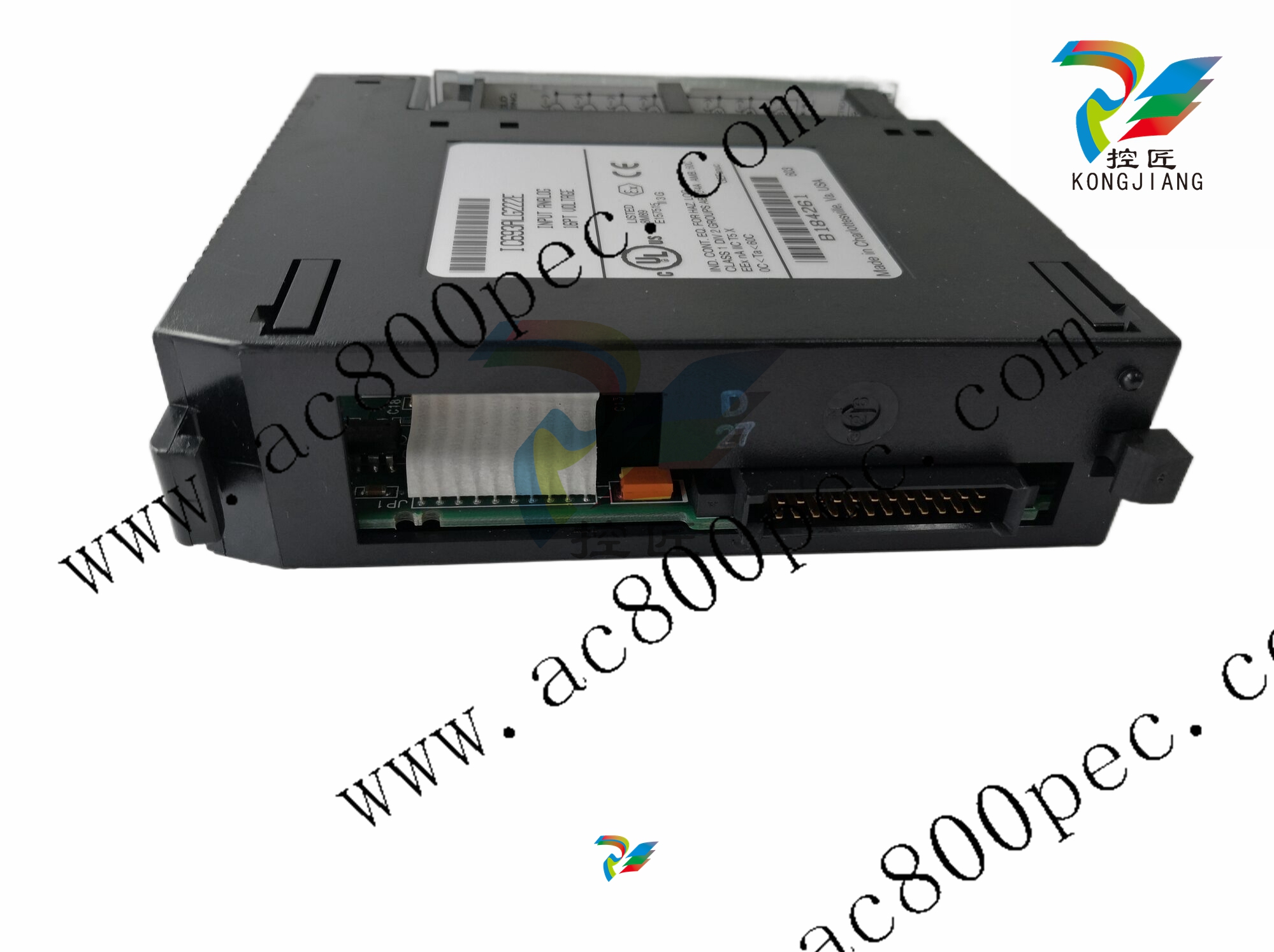
Description
The Analog Output Module with 4 isolated outputs is an intelligent
module that controls to up to 4 analog devices.
GE IC200ALG331 Analog Output Module
In current mode, a separate power supply may be required for
isolated inputs.
Module features include:
Four isolated 4-20mA current output channels
Software configuration, no jumpers or switches
Sixteen bit converter resolution
High accuracy factory calibration
The following features are software-configurable:
Per-channel selection of 4-20mA current or +/–10V voltage outputs
Selection of default/hold last state operation
Per-channel selection of default values
Per-channel selection of under-range and over-range
diagnostics levels
Per-channel selection of alarm levels
Per-channel scaling
Field re-calibration on command
Host Interface_______________________________________
The module receives 4 words of analog output data from the system.
Diagnostics ________________________________________
The module reports High/Low Limit, Over/Underrange, Open Wire,
Loss of Field Power Supply, and Non-volatile memory fault
diagnostics.
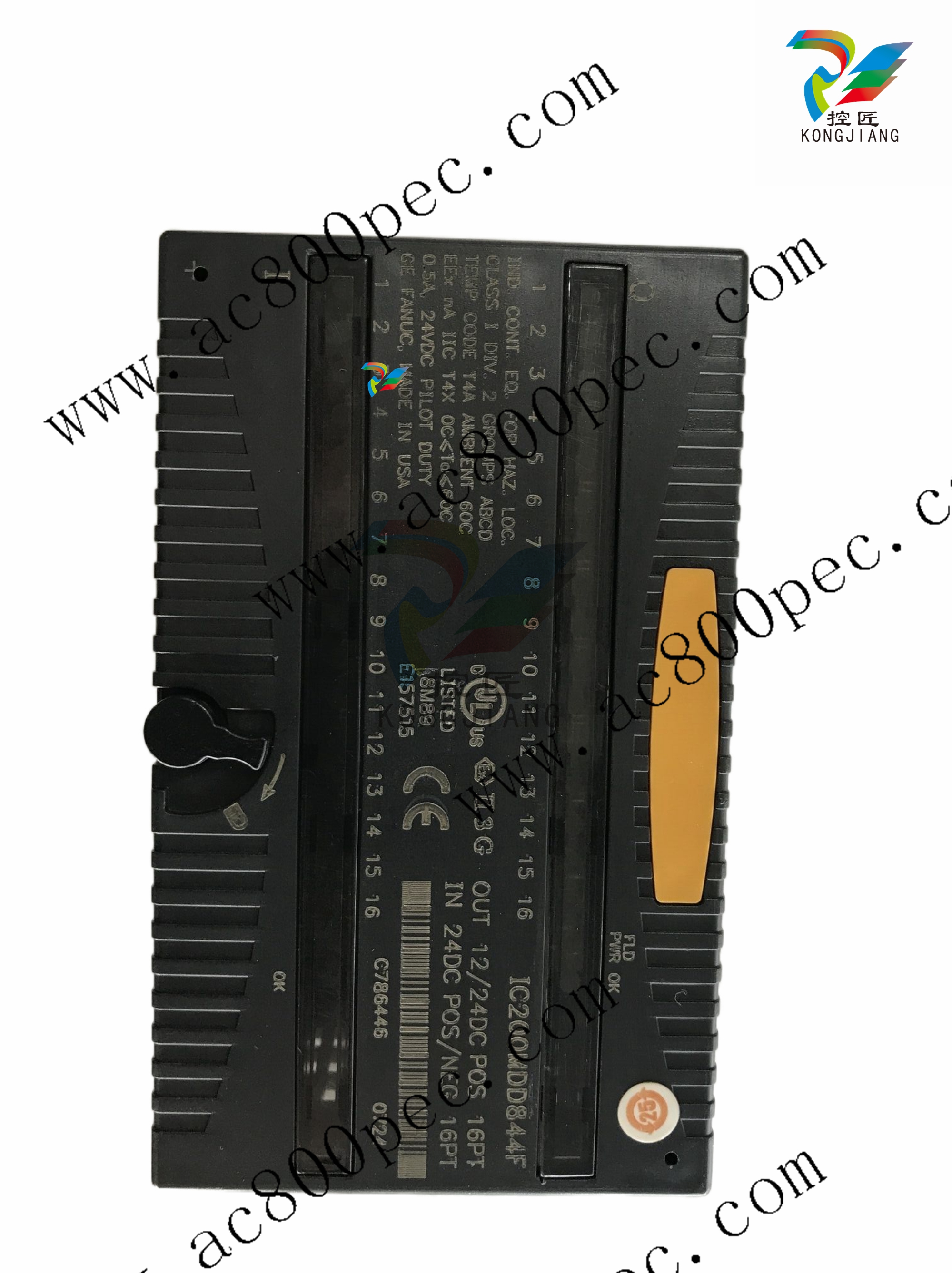
LED Indicators ______________________________________
The green FLD PWR LED indicates the presence of both logic
power and field power for the analog field-side circuits. It does not
indicate the presence of other supplies such as current loop supplies
on output points. The absence of either backplane or field power
turns off the FLD PWR LED.
The OK LED indicates module status:
On green indicates normal operation.
Flashing green indicates boot mode or update
Flashing amber indicates self-diagnostic error.
Off indicates no 3.3V power
Note that this module is the only one that has its OK LED located
before the FLD PWR LED in the A slot.
Module Characteristics
Channels 4 outputs
Module ID FFFF9805
Isolation:
User input to logic (optical)
and to frame ground,
Group to Group
Channel to channel
250VAC continuous; 1500VAC for 1 minute
Not applicable
250VAC continuous; 1500VAC for 1 minute
LED indicators FLD PWR LED indicates the presence of both logic
power and user power. OK LED indicates module
status.
Backplane current
consumption
5V output: 10mA maximum.
3.3V output: 115mA maximum
Configuration parameters Output default
External power supply:
Range
Current consumption
+18 to +30VDC including ripple
100mA maximum plus load currents
Thermal derating None
Diagnostics High/Low Limit, Over/Underrange, Open Wire, Loss of
Field Power Supply, Non-volatile memory fault
Output Characteristics
Output operating range Current mode: +1 to 20mA
Voltage mode: +/-10VDC
Accuracy at 25 degrees C +/- 0.1% maximum of full scale
Temperature coefficient Current mode: 45ppm/°C typical, 90 ppm/°C maximum
Voltage mode: 30ppm/°C typical, 60 ppm/°C maximum
Load characteristics Current mode: 0 to 1250 ohms
Voltage mode: 2K ohms minimum
Analog Resolution (1LSB) Current mode: 381 nA nominal
Voltage mode: 381 µV nominal
Update rate 7mS maximum
Channel-to-channel
crosstalk rejection
70dB minimum
Output default Hold Last State (default)
0 (configurable)
Preinstallation Check
Carefully inspect all shipping containers for damage. If any equipment is
damaged, notify the delivery service immediately. Save the damaged
shipping container for inspection by the delivery service. After unpacking
the equipment, record all serial numbers. Save the shipping containers
and packing material in case it is necessary to transport or ship any part
of the system.
Field Wiring Terminals
Terminal assignments for the module are shown below.
Number Connection Number Connection
A1 No connection B1 I1+
A2 Shield Ground B2 I1-
A3 No connection B3 V1+
A4 Shield Ground B4 V1-
A5 No connection B5 I2+
A6 Shield Ground B6 I2-
A7 No connection B7 V2+
A8 Shield Ground B8 V2-
A9 No connection B9 I3+
A10 Shield Ground B10 I3-
A11 No connection B11 V3+
A12 Shield Ground B12 V3-
A13 No connection B13 I4+
A14 Shield Ground B14 I4-
A15 No connection B15 V4+
A16 Shield Ground B16 V4-
A17 No connection B17 DC -
A18 No connection B18 DC+
A 24 volt power supply must be connected to B17 and B18 to
operate the module.
Voltage outputs are powered from the module. For each channel, V+
is positive with respect to V- when the channel’s output data is
positive.
Current outputs act as current regulators and require a supply to
power the load. The current loop can be connected either as a
current source or as a current sink to the load.
The loads are isolated if the loop supply is isolated. However, if the
module supply is also used as the loop supply, the loads are not
isolated.
Wiring Connections for Carriers with Two Rows of Terminals
Shielded twisted pair cable is recommended for the analog channel
connections.
If the module is installed on a Terminal-style I/O Carrier or a Compact
Terminal-style I/O Carrier, the cable shield can be connected directly to
the carrier.
If the module is installed on a Connector-style I/O Carrier, the cable
shield can be connected directly to an Interposing Terminal. A shielded
interposing cable (shielded cables are available separately) must be
used between the Connector-style I/O Carrier and the Interposing
Terminal.
An Auxiliary I/O Terminal Strip can also be added to the Interposing
Terminal if additional shield connections are required.
Purchase history
| User name | Member Level | Quantity | Specification | Purchase Date |
|---|
Total 0 Record
Customer Reviews
Satisfaction :
5 Stars
No evaluation information


- other
- LTI Drives
- ADLINK
- Beckhoff
- Other Brands
- AMAT
- Iba
- PEPPERL+FUCHS
- Aerotech
- WATLOW
- MAN
- ADVANCED
- Abaco
- YOKOGAWA
- KOLLMORGEN
- MEGGITT
- kong-sberg
- METSO
- Motorola
- NI
- OEMAX
- RELIANCE
- scanlab
- schneider
- uniop
- Vibro-Meter
- Honeywell
- Rolls-Royce
- MOOG
- GE
- B&R
- Woodward
- Yaskawa
- xYCOM
- Siemens
- Emerson
- HIMA
- Bently
- ZYGO
- FOXBORO
- OMACO
- PROSOFT
- ENTERASYS
- TRICONEX
- Parker
- Lenze
- KEBA
- Alstom
- CTI
- ABB
- A-B
145

-
 ADLINK PCI-9112/cPCI-9112 multifunctional acquisition card
 -
 ADLINK PCI-8102 Two Axis Pulse Motion Control Card
 -
 ADLINK PCI-9812/PCI-9810 synchronous 4-channel high-speed acquisition card
 -
 ADLINK PCI-7200/cPCI-7200 high-speed digital I/O board
 -
 ADLINK MXE-1000 series fanless embedded machine
 -
 ADLINK IMB-T10 Mini ITX Industrial Motherboard
 -
 ADLINK HSL Distributed High Speed I/O System
 -
 ADLINK PXI/DAQ/DAQe-2500 series multifunctional analog output DAQ card
 -
 ADLINK PXI/DAQ/DAQe-2200 series multifunctional data acquisition card
 -
 ADLINK ETX-AT ETX Core Computer Module
 -
 ADLINK ACL-7225 ISA 16 channel relay output+16 channel isolated digital input card
 -
 ADLINK DAQ-2000 series synchronous acquisition card
 -
 ADLINK NuPRO-E330 PICMG 1.3 full-length industrial motherboard (SHB)
 -
 ADLINK ACL-8112 series multifunctional ISA acquisition card
 -
 ADLINK USB-2405 24 bit dynamic signal acquisition module
 -
 ADLINK PXIS-3320 15 slot 6U PXI chassis
 -
 ADLINK PCIe GIE7x series acquisition card
 -
 ADLINK PCIe-7856/PCIe-7853 Distributed Motion and IO Main Controller PCIe Acquisition Card
 -
 ADLINK PCI-6308 series isolated analog output board
 -
 ADLINK PCI-7432 Isolated Digital I/O Acquisition Card
 -
 ADLINK NuPRO-E72 PICMG 1.3 Full length Industrial SHB Single Board Computer
 -
 ADLINK MXE-5400 series fanless embedded industrial computer
 -
 ADLINK M-322 Industrial ATX Motherboard
 -
 ADLINK IMB-M43H Industrial ATX Motherboard
 -
 ADLINK IMB-M42H Industrial ATX Motherboard
 -
 ADLINK i915GV-INA ATX motherboard
 -
 ADLINK ETX-NR667 Embedded ETX Standard Computer Module
 -
 ADLINK ETX-BT (PATA to SATA version) User Manual
 -
 ADLINK CM1-BT1 PC/104 Single Board Computer
 -
![ADLINK cPCI-8217 [R] 3U CompactPCI VGA/LCD Display Module](https://aosspic10001.websiteonline.cn/hkw632bc8/image/image_aJXQRn.png) ADLINK cPCI-8217 [R] 3U CompactPCI VGA/LCD Display Module
ADLINK cPCI-8217 [R] 3U CompactPCI VGA/LCD Display Module -
 ADLINK AmITX-SL-G Mini ITX Embedded Motherboard
 -
 ADLINK AmITX-AL-I ultra-thin Mini ITX industrial motherboard
 -
 ADLINK NuPRO-E315 Full length PICMG 1.3 Industrial SHB Single Board Computer
 -
 ADLINK NuPRO-842 Full length PICMG 1.0 PCI/ISA Industrial Single Board Computer
 -
 ADLINK NuPRO-900A PICMG 1.2 ePCI-X Dual Xeon Industrial System Motherboard (SHB)
 -
 ADLINK cPCI-6910 series 6U CompactPCI single board computer
 -
 ADLINK cPCI-6860A 6U CompactPCI dual core single board computer with cPCI-R6860A rear adapter board
 -
 ADLINK cPCI-8168 6U CompactPCI Eight Axis Motion Control Card
 -
 ADLINK NuPRO-E340 PICMG 1.3 Industrial SHB motherboard
 -
 ADLINK NuPRO-A40H Full length PICMG1.0 Industrial Single Board Computer (SBC)
 -
 ADLINK NuPRO-852 Full length PICMG1.0 Industrial Single Board Computer
 -
 ADLINK NuPRO-841 Full length Industrial SBC
 -
 ADLINK NuPRO-590/591/592 series Socket7 full-length industrial SBC
 -
 ADLINK MXE-5500 series fanless embedded industrial computer
 -
 ADLINK MXE-200/200i Fanless Embedded Machine
 -
 ADLINK cPCI-6770 series CompactPCI CPU board
 -
 ADLINK NuPRO-A301 standard PICMG 1.0 full-length industrial SBC single board computer
 -
 ADLINK NuPRO-965 PICMG 1.3 SHB Express Full length Industrial Motherboard
 -
 ADLINK NuPRO-935A Full length PICMG1.0 Industrial Single Board Computer
 -
 ADLINK NuPRO-865 Full length Single Board Computer
 -
 ADLINK NuPRO-840 DV/LV Full Length PICMG Industrial Single Board Computer
 -
 ADLINK NuPRO-770 series full-length industrial single board computer
 -
 ADLINK NuPRO-595 series half length Socket 7 industrial motherboard
 -
 ADLINK cPCI-6840 series 6U CompactPCI single board computer
 -
 Foxboro 43AP series pneumatic indicator controller (PSS 3-1B3 A)
 -
 ADLINK cPCI-3720 Series 3U Low Power CompactPCI Single Board Computer
 -
 ADLINK NuPRO-E47, PICMG 1.3 full-length industrial SHB system motherboard
 -
 ADLINK NuPRO-E43 PICMG 1.3 full-length system motherboard
 -
 ADLINK NuPRO-780 series full-length industrial CPU board
 -
 ADLINK cPCI-6965 series 6U CPCI single board computer
 -
 ADLINK USB/LPCI/LPCIe-3488A GPIB interface card
 -
 Rittal SK 3241.700 Blue e+Fan Filter Unit
 -
 ADLINK cPCI-8168 6U CompactPCI 8-Axis Motion Control Card
 -
 ADLINK PCIe PXIe-8638 PCIe to PXIe Bus Expansion Kit
 -
 ADLINK PCIe GIE7x series acquisition card
 -
 ADLINK PCIe-7396 96 96 channel TTL digital IO card
 -
 ADLINK PCI/MPC/PXI-8164 Three in One Motion Control Card
 -
 ADLINK PCI-8154 Four Axis Pulse Motion Control Card
 -
 ADLINK PCI-8134 Four Axis Servo/Stepper Motion Control Card
 -
 ADLINK NuPRO-E42 PICMG1.3 full-length SHB motherboard
 -
 ADLINK MXC-6600 series high-performance fanless extended industrial computer
 -
 ADLINK MXC-6000 series embedded industrial control computer
 -
 ADLINK MXC-2300 series fanless expandable embedded industrial computer
 -
 ADLINK MCM-204 Independent Ethernet DAQ User Manual
 -
 ADLINK MCM-100/102 Edge IoT Platform for Machine Condition Monitoring User’s Manual
 -
 ADLINK MXC-6400 series sixth generation Core Fanless Scalable Industrial Control Computer
 -
 ADLINK Matrix Full Series Fanless Embedded Industrial Control Computers
 -
 ADLINK GIE64+4-channel PoE Gigabit Vision Capture Card
 -
 Honeywell UMS Security System Troubleshooting Guide
 -
 Honeywell Expert Series-C I/O Module
 -
 ADLINK EOS-1200 Embedded Vision Host
 -
 ADLINK DLAP-5200 series high-performance fanless AI industrial computer
 -
 ADLINK DLAP-4000 series embedded industrial control computer
 -
 ADLINK Matrix MXC-2000 Series Fanless Industrial Control Computer Specification
 -
 ADLINK DAQ -/DAQE -/PXI-2000 Series Multi functional Synchronous Acquisition Card
 -
 ADLINK cPCI-6520 6U CompactPCI Single Board Computer
 -
 ADLINK CM1-86DX3 PC/104 Single Board Computer
 -
 Honeywell DC1000 series PID temperature controller
 -
 ALSTOM MiCOM C264 Modular Substation Controller
 -
 EMERSON AMS 2140 Mechanical Health Analyzer
 -
 ADLINK NuPRO-E320 PICMG1.3 Full length Industrial Motherboard
 -
 ADLINK NuPRO-800 Series Full length Industrial SBC User Manual
 -
 ADLINK NuPRO-598 Industrial Single Board Computer
 -
 ADLINK MXC-6300 Fanless Embedded Industrial Control Computer
 -
 ADLINK Express-BASE7 User Manual
 -
 ADLINK DLAP-211 Series Fanless Edge AI Platform Specification Manual
 -
 ADLINK PCI/LPCI/LPCIe/cPCI-723X series 32 channel isolated digital I/O card
 -
 ADLINK cPCI-6965 series 6U CompactPCI single board computer
 -
 ADLINK NuDAQ 7200 series high-speed digital I/O board
 -
 Linghua ADLINK DLAP Deep Learning Acceleration Platform Product Manual
 -
 DEIF TCM-2 thyristor control module
 -
 Installation Manual for DEIF MVR-200 Series Medium Voltage Protection Device
 -
 DEIF MDR-2 multifunctional differential relay
 -
 DEIF AOM-1 Analog Output Module
 -
 DEIF AGI 400 series industrial/marine touch screen
 -
 Installation Manual for DEIF BRW-1 Marine Wing Bridge Instrument
 -
 DEIF AGC200 Quick Start Guide
 -
 DEIF AGC Multi line 2 Generator Set ControllerProduct basic information
 -
 ABB SPA-ZC 400 Ethernet Gateway Installation and Debugging Manual
 -
 ABB REM 543/545 motor generator protection device
 -
 DEIF PPU 300 controller
 -
 DEIF Delomatic 4 Offshore/Ocean Platform Dedicated Generator Power Management System DM-4
 -
 DEIF Delomatic Modular Generator Set Integrated System
 -
 DEIF AGC-4 Mk II Generator Set Controller
 -
 DEIF AGC-4 diesel generator set integrated controller
 -
 DEIF Multi line 2 Series PPU Unit Power Management (PPM) Operation Manual
 -
 DEIF Multi line 2 V2.4X Installation Manual
 -
 Beckwith M-6280 Digital Capacitor Bank Controller
 -
 Beckwith M-3311 Transformer Protection Relay
 -
 Beckwith M-3311A Transformer Integrated Protection Device
 -
 Beckwith M-3310 Transformer Integrated Protection Device Specification
 -
 Beckwith M-0359 Syncrocloser Check Plus Application Guide for Synchronous Calibration Relay
 -
 Beckwith M-0293A On Load Tap changer Controller Application Guide
 -
 DEIF GPU-3 Synchronous/Asynchronous Generator Integrated Microcomputer Protection Controller
 -
 Installation Instructions for DEIF PPM-3
 -
 Beckwith M-3520 distributed power grid connected comprehensive protection device
 -
 Beckwith M-3430 generator comprehensive protection device
 -
 Beckwith M-2293B adapter panel

K-JIANG

Add: Jimei North Road, Jimei District, Xiamen, Fujian, China
Tell:+86-15305925923