
K-WANG


- Telephone:+86-15305925923
- contacts:Mr.Wang
- Email:wang@kongjiangauto.com
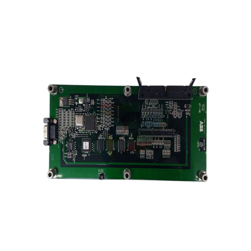
ABB SPDSI14 DSI14 Digital Input Module
Overview
Product Definition and Function: The ABB SPDSI14 DSI14 Digital Input Module is a module designed by ABB for industrial automation control systems to receive and process digital input signals. It is responsible for converting digital signals (e.g. on/off signals, pulse signals, etc.) generated by external devices (e.g. sensors, switches, etc.) into recognisable digital levels within the module and transmitting these signals to the control system for subsequent logical judgements, control decisions and other operations.
Working Principle
Signal reception and conditioning: The module has several digital input channels, usually 14 channels. These channels can receive many types of digital signals, such as signals from proximity switches, photoelectric switches, limit switches and other devices. When an external digital signal is connected to the module's input channels, it first passes through a signal conditioning circuit. This circuit mainly performs filtering, level conversion and buffering on the signal. Filtering is to remove high-frequency noise and interference components in the signal to ensure the purity of the input signal; level conversion is to convert the level of the external signal to the standard level that can be processed within the module, for example, to convert external signals of different voltage levels to a unified logic level within the module (such as TTL or CMOS levels); buffering is to enhance the driving ability of the signal to ensure that the signal can be stably Buffering enhances the driving capability of the signals to ensure stable transmission to the subsequent circuits.
Signal Detection and Conversion: The conditioned signal is fed into the signal detection circuit. This circuit detects the level state (high or low) of the signal and converts it into a digital logic signal (e.g. ‘1’ for high level, ‘0’ for low level). For pulsed signals, the rising and falling edges of the pulse can also be detected and operations such as counting or time measurement can be performed. For example, when a proximity switch detects an object approaching and outputs a high level signal, the module's signal detection circuit will convert this high level to a digital ‘1’ and store this signal state in an internal register.
Data transmission and communication: The converted digital signals are stored in the internal registers of the module, and then these signals are transmitted to the control system through the communication interface. The module supports a variety of communication protocols, such as Industrial Ethernet, Profibus, Modbus, etc., which enables good data interaction with different control systems. The control system processes the received digital signals accordingly, such as starting and stopping the motor according to the switching signal, or calculating the running speed of the equipment according to the pulse signal.
Performance features
High Reliability Signal Acquisition: It has high reliability in the signal acquisition process and can effectively resist the interference in the industrial environment. Its signal filtering function can remove most of the electromagnetic interference (EMI) and radio frequency interference (RFI), to ensure that the collected signal is true and reliable. At the same time, the level conversion and buffer processing of the signal conditioning circuit also improves the stability of the signal and reduces false judgements caused by signal fluctuations.
Multi-Channel Input Design: The design of 14 digital input channels makes it possible to receive multiple digital signals at the same time, which facilitates the status monitoring of multiple external devices. For example, in an automated production line, multiple sensors can be connected at the same time to detect the position of equipment, the presence or absence of materials and other status, thus realising comprehensive monitoring of the entire production line.
Flexible Signal Processing Capability: Supports multiple types of digital signal processing, not only for simple switching signals, but also for pulse signals. For pulse signals, operations such as counting, frequency measurement, and period measurement can be performed. This flexibility allows it to adapt to different industrial application scenarios and meet diverse control needs.
Fast Response Characteristics: With fast response time, it is able to detect changes in the input signal and transmit them to the control system in a short period of time. The response time is generally within a few milliseconds (ms), which is very important for industrial control scenarios that require fast response (such as emergency stop systems, high-speed counting equipment, etc.) to ensure that the system responds in a timely manner.
Technical Parameters
Input parameters
Number of input channels: 14, each channel can receive digital signals independently.
Input Signal Type and Level Range: A wide range of digital signals can be received, including, but not limited to, TTL (Transistor Transistor Logic) level signals, CMOS (Complementary Metal Oxide Semiconductor) level signals, and dry contact signals (e.g., on/off signals for switches). For level ranges, TTL level signals generally have a high level range of 2V - 5V and a low level range of 0V - 0.8V; CMOS level signals have a high level range and a low level range that vary according to the specific CMOS device, but are usually in a similar range; dry contact signals do not have strict level requirements, as long as they can form an effective on/off state.
Signal Processing Parameters
Signal Filtering Characteristics: It has the function of filtering, which can filter out the high-frequency interfering signals, and the frequency range of filtering can be set according to the user's demand, and it can usually filter out the interfering signals with the frequency higher than a few kilohertz (kHz).
Pulse Processing Capability: For pulse signals, it can perform counting, frequency measurement and period measurement. The counting accuracy can reach ±1 pulse, the frequency measurement accuracy can reach ±0.1% - ±0.5% reading accuracy, and the cycle measurement accuracy can also reach a high level, generally within the range of ±0.1% - ±0.5% cycle reading accuracy.
Communication Parameters
Supported communication protocols: Support a variety of industrial communication protocols, such as Industrial Ethernet (Ethernet/IP), Profibus, Modbus, etc., to facilitate integration with different control systems.
Communication rate: The communication rate varies depending on the protocol. For example, in industrial Ethernet communication, the communication rate can reach 10Mbps - 1000Mbps; in Profibus communication, the communication rate can reach 12Mbps - 100Mbps; in Modbus communication, the communication rate can vary from 9600bps - 115200bps.
Physical Parameters
Dimensions: The external dimensions are generally designed according to the installation requirements, the length may be between 10cm - 20cm, the width between 5cm - 10cm, the thickness between 3cm - 8cm, which is easy to be installed in the standard card slot of the control cabinet or the installation position of the equipment.
Weight: Light weight, usually between 100g - 500g, will not cause excessive burden on the overall weight and installation of the equipment.
Environmental parameters
Operating temperature range: can work in a wide range of temperature, generally - 20 ℃ - + 60 ℃, can adapt to different industrial site temperature conditions.
Humidity range: The relative humidity range is usually 10% - 90% (non-condensing), ensuring normal operation in different humidity environments.
| User name | Member Level | Quantity | Specification | Purchase Date |
|---|


- other
- LTI Drives
- ADLINK
- Beckhoff
- Other Brands
- AMAT
- Iba
- PEPPERL+FUCHS
- Aerotech
- WATLOW
- MAN
- ADVANCED
- Abaco
- YOKOGAWA
- KOLLMORGEN
- MEGGITT
- kong-sberg
- METSO
- Motorola
- NI
- OEMAX
- RELIANCE
- scanlab
- schneider
- uniop
- Vibro-Meter
- Honeywell
- Rolls-Royce
- MOOG
- GE
- B&R
- Woodward
- Yaskawa
- xYCOM
- Siemens
- Emerson
- HIMA
- Bently
- ZYGO
- FOXBORO
- OMACO
- PROSOFT
- ENTERASYS
- TRICONEX
- Parker
- Lenze
- KEBA
- Alstom
- CTI
- ABB
- A-B

-
 ADLINK PCI-9112/cPCI-9112 multifunctional acquisition card
 -
 ADLINK PCI-8102 Two Axis Pulse Motion Control Card
 -
 ADLINK PCI-9812/PCI-9810 synchronous 4-channel high-speed acquisition card
 -
 ADLINK PCI-7200/cPCI-7200 high-speed digital I/O board
 -
 ADLINK MXE-1000 series fanless embedded machine
 -
 ADLINK IMB-T10 Mini ITX Industrial Motherboard
 -
 ADLINK HSL Distributed High Speed I/O System
 -
 ADLINK PXI/DAQ/DAQe-2500 series multifunctional analog output DAQ card
 -
 ADLINK PXI/DAQ/DAQe-2200 series multifunctional data acquisition card
 -
 ADLINK ETX-AT ETX Core Computer Module
 -
 ADLINK ACL-7225 ISA 16 channel relay output+16 channel isolated digital input card
 -
 ADLINK DAQ-2000 series synchronous acquisition card
 -
 ADLINK NuPRO-E330 PICMG 1.3 full-length industrial motherboard (SHB)
 -
 ADLINK ACL-8112 series multifunctional ISA acquisition card
 -
 ADLINK USB-2405 24 bit dynamic signal acquisition module
 -
 ADLINK PXIS-3320 15 slot 6U PXI chassis
 -
 ADLINK PCIe GIE7x series acquisition card
 -
 ADLINK PCIe-7856/PCIe-7853 Distributed Motion and IO Main Controller PCIe Acquisition Card
 -
 ADLINK PCI-6308 series isolated analog output board
 -
 ADLINK PCI-7432 Isolated Digital I/O Acquisition Card
 -
 ADLINK NuPRO-E72 PICMG 1.3 Full length Industrial SHB Single Board Computer
 -
 ADLINK MXE-5400 series fanless embedded industrial computer
 -
 ADLINK M-322 Industrial ATX Motherboard
 -
 ADLINK IMB-M43H Industrial ATX Motherboard
 -
 ADLINK IMB-M42H Industrial ATX Motherboard
 -
 ADLINK i915GV-INA ATX motherboard
 -
 ADLINK ETX-NR667 Embedded ETX Standard Computer Module
 -
 ADLINK ETX-BT (PATA to SATA version) User Manual
 -
 ADLINK CM1-BT1 PC/104 Single Board Computer
 -
![ADLINK cPCI-8217 [R] 3U CompactPCI VGA/LCD Display Module](https://aosspic10001.websiteonline.cn/hkw632bc8/image/image_aJXQRn.png) ADLINK cPCI-8217 [R] 3U CompactPCI VGA/LCD Display Module
ADLINK cPCI-8217 [R] 3U CompactPCI VGA/LCD Display Module -
 ADLINK AmITX-SL-G Mini ITX Embedded Motherboard
 -
 ADLINK AmITX-AL-I ultra-thin Mini ITX industrial motherboard
 -
 ADLINK NuPRO-E315 Full length PICMG 1.3 Industrial SHB Single Board Computer
 -
 ADLINK NuPRO-842 Full length PICMG 1.0 PCI/ISA Industrial Single Board Computer
 -
 ADLINK NuPRO-900A PICMG 1.2 ePCI-X Dual Xeon Industrial System Motherboard (SHB)
 -
 ADLINK cPCI-6910 series 6U CompactPCI single board computer
 -
 ADLINK cPCI-6860A 6U CompactPCI dual core single board computer with cPCI-R6860A rear adapter board
 -
 ADLINK cPCI-8168 6U CompactPCI Eight Axis Motion Control Card
 -
 ADLINK NuPRO-E340 PICMG 1.3 Industrial SHB motherboard
 -
 ADLINK NuPRO-A40H Full length PICMG1.0 Industrial Single Board Computer (SBC)
 -
 ADLINK NuPRO-852 Full length PICMG1.0 Industrial Single Board Computer
 -
 ADLINK NuPRO-841 Full length Industrial SBC
 -
 ADLINK NuPRO-590/591/592 series Socket7 full-length industrial SBC
 -
 ADLINK MXE-5500 series fanless embedded industrial computer
 -
 ADLINK MXE-200/200i Fanless Embedded Machine
 -
 ADLINK cPCI-6770 series CompactPCI CPU board
 -
 ADLINK NuPRO-A301 standard PICMG 1.0 full-length industrial SBC single board computer
 -
 ADLINK NuPRO-965 PICMG 1.3 SHB Express Full length Industrial Motherboard
 -
 ADLINK NuPRO-935A Full length PICMG1.0 Industrial Single Board Computer
 -
 ADLINK NuPRO-865 Full length Single Board Computer
 -
 ADLINK NuPRO-840 DV/LV Full Length PICMG Industrial Single Board Computer
 -
 ADLINK NuPRO-770 series full-length industrial single board computer
 -
 ADLINK NuPRO-595 series half length Socket 7 industrial motherboard
 -
 ADLINK cPCI-6840 series 6U CompactPCI single board computer
 -
 Foxboro 43AP series pneumatic indicator controller (PSS 3-1B3 A)
 -
 ADLINK cPCI-3720 Series 3U Low Power CompactPCI Single Board Computer
 -
 ADLINK NuPRO-E47, PICMG 1.3 full-length industrial SHB system motherboard
 -
 ADLINK NuPRO-E43 PICMG 1.3 full-length system motherboard
 -
 ADLINK NuPRO-780 series full-length industrial CPU board
 -
 ADLINK cPCI-6965 series 6U CPCI single board computer
 -
 ADLINK USB/LPCI/LPCIe-3488A GPIB interface card
 -
 Rittal SK 3241.700 Blue e+Fan Filter Unit
 -
 ADLINK cPCI-8168 6U CompactPCI 8-Axis Motion Control Card
 -
 ADLINK PCIe PXIe-8638 PCIe to PXIe Bus Expansion Kit
 -
 ADLINK PCIe GIE7x series acquisition card
 -
 ADLINK PCIe-7396 96 96 channel TTL digital IO card
 -
 ADLINK PCI/MPC/PXI-8164 Three in One Motion Control Card
 -
 ADLINK PCI-8154 Four Axis Pulse Motion Control Card
 -
 ADLINK PCI-8134 Four Axis Servo/Stepper Motion Control Card
 -
 ADLINK NuPRO-E42 PICMG1.3 full-length SHB motherboard
 -
 ADLINK MXC-6600 series high-performance fanless extended industrial computer
 -
 ADLINK MXC-6000 series embedded industrial control computer
 -
 ADLINK MXC-2300 series fanless expandable embedded industrial computer
 -
 ADLINK MCM-204 Independent Ethernet DAQ User Manual
 -
 ADLINK MCM-100/102 Edge IoT Platform for Machine Condition Monitoring User’s Manual
 -
 ADLINK MXC-6400 series sixth generation Core Fanless Scalable Industrial Control Computer
 -
 ADLINK Matrix Full Series Fanless Embedded Industrial Control Computers
 -
 ADLINK GIE64+4-channel PoE Gigabit Vision Capture Card
 -
 Honeywell UMS Security System Troubleshooting Guide
 -
 Honeywell Expert Series-C I/O Module
 -
 ADLINK EOS-1200 Embedded Vision Host
 -
 ADLINK DLAP-5200 series high-performance fanless AI industrial computer
 -
 ADLINK DLAP-4000 series embedded industrial control computer
 -
 ADLINK Matrix MXC-2000 Series Fanless Industrial Control Computer Specification
 -
 ADLINK DAQ -/DAQE -/PXI-2000 Series Multi functional Synchronous Acquisition Card
 -
 ADLINK cPCI-6520 6U CompactPCI Single Board Computer
 -
 ADLINK CM1-86DX3 PC/104 Single Board Computer
 -
 Honeywell DC1000 series PID temperature controller
 -
 ALSTOM MiCOM C264 Modular Substation Controller
 -
 EMERSON AMS 2140 Mechanical Health Analyzer
 -
 ADLINK NuPRO-E320 PICMG1.3 Full length Industrial Motherboard
 -
 ADLINK NuPRO-800 Series Full length Industrial SBC User Manual
 -
 ADLINK NuPRO-598 Industrial Single Board Computer
 -
 ADLINK MXC-6300 Fanless Embedded Industrial Control Computer
 -
 ADLINK Express-BASE7 User Manual
 -
 ADLINK DLAP-211 Series Fanless Edge AI Platform Specification Manual
 -
 ADLINK PCI/LPCI/LPCIe/cPCI-723X series 32 channel isolated digital I/O card
 -
 ADLINK cPCI-6965 series 6U CompactPCI single board computer
 -
 ADLINK NuDAQ 7200 series high-speed digital I/O board
 -
 Linghua ADLINK DLAP Deep Learning Acceleration Platform Product Manual
 -
 DEIF TCM-2 thyristor control module
 -
 Installation Manual for DEIF MVR-200 Series Medium Voltage Protection Device
 -
 DEIF MDR-2 multifunctional differential relay
 -
 DEIF AOM-1 Analog Output Module
 -
 DEIF AGI 400 series industrial/marine touch screen
 -
 Installation Manual for DEIF BRW-1 Marine Wing Bridge Instrument
 -
 DEIF AGC200 Quick Start Guide
 -
 DEIF AGC Multi line 2 Generator Set ControllerProduct basic information
 -
 ABB SPA-ZC 400 Ethernet Gateway Installation and Debugging Manual
 -
 ABB REM 543/545 motor generator protection device
 -
 DEIF PPU 300 controller
 -
 DEIF Delomatic 4 Offshore/Ocean Platform Dedicated Generator Power Management System DM-4
 -
 DEIF Delomatic Modular Generator Set Integrated System
 -
 DEIF AGC-4 Mk II Generator Set Controller
 -
 DEIF AGC-4 diesel generator set integrated controller
 -
 DEIF Multi line 2 Series PPU Unit Power Management (PPM) Operation Manual
 -
 DEIF Multi line 2 V2.4X Installation Manual
 -
 Beckwith M-6280 Digital Capacitor Bank Controller
 -
 Beckwith M-3311 Transformer Protection Relay
 -
 Beckwith M-3311A Transformer Integrated Protection Device
 -
 Beckwith M-3310 Transformer Integrated Protection Device Specification
 -
 Beckwith M-0359 Syncrocloser Check Plus Application Guide for Synchronous Calibration Relay
 -
 Beckwith M-0293A On Load Tap changer Controller Application Guide
 -
 DEIF GPU-3 Synchronous/Asynchronous Generator Integrated Microcomputer Protection Controller
 -
 Installation Instructions for DEIF PPM-3
 -
 Beckwith M-3520 distributed power grid connected comprehensive protection device
 -
 Beckwith M-3430 generator comprehensive protection device
 -
 Beckwith M-2293B adapter panel

K-JIANG

Add: Jimei North Road, Jimei District, Xiamen, Fujian, China
Tell:+86-15305925923