
K-WANG
+086-15305925923
Service expert in industrial control field!


Product
Article
NameDescriptionContent
Adequate Inventory, Timely Service
pursuit of excellence


Ship control system
Equipment control system
Power monitoring system
Brand
Product parameters
- Telephone:+86-15305925923
- contacts:Mr.Wang
- Email:wang@kongjiangauto.com
Description
One of the module
diagnostics in the
associated rack is set
to MISMATCH, BAD
MODULE, BAD
CHANNEL., or
MISSING/NO COMM
(if the communications is failing due to the
module not installed—could occur
if the module is installed but CPU can’t communicate to it).
Honeywell Controller C70 CPU 900C70-0360-00
Item Status Possible Cause Controller Action What to do MODULE ERROR One of the module
diagnostics in the
associated rack is set
to MISMATCH, BAD
MODULE, BAD
CHANNEL., or
MISSING/NO COMM
(if the
communications is
failing due to the
module not
installed—could occur
if the module is
installed but CPU
can’t communicate toit).
Select I/O from the menu
to see details on the faulty
module. See I/O Module
Diagnostics on page 42.
Select I/O from the menu to see details
on the faulty module. See I/O Module
Diagnostics on page 42.
MODULE HI CJ
TEMP
One of the module
diagnostics in the
associated rack is set
to HI CJ
TEMPERATURE.
Select I/O from the menu
to see details on the faulty
module. See I/O Module
Diagnostics on page 42.
Select I/O from the menu to see details
on the faulty module. See I/O Module
Diagnostics on page 42.
FAILURE The Controller
module is unable to
successfully
communicate to any
modules that are in its
SPI backplane.
All associated module
diagnostics are set to
MISSING/NO COMM.
See MISSING/NO COMM
in Table 22 I/O Module
Error Status on page 44 for
further details.
1. Remove modules and check for bent
pins on connectors.
2. Reinsert modules one at a time and
note which module the diagnostic
reoccurs, and replace that module.
3. Cycle power to the rack.
4. Replace the power supply.
5. Replace the rack.
6. Replace the CPU board.
NO COMM The Main CPU is
unable to successfully
communicate to an
expansion rack that is
in its configuration.
See FAILURE. 1. Verify that the expansion rack should
be in the configuration
2. Verify that the jumpers on the
scanner are setup for the correct rack
address.
3. Check that expansion rack is on.
4. Check the expansion rack’s status
LED for diagnostic information.
5. Check that cable is connected to
expansion rack.
6. If a hub is used, check that all cables
are properly connected to the hub,
proper crossover cables are used, and
that hub is powered.
7. Cycle power to the rack.
8. Cycle power to the hub.
9. Replace the expansion rack’s power
supply.
10. Replace the expansion rack.
11. Replace the expansion rack’s
scanner board.
12. Replace the main CPU.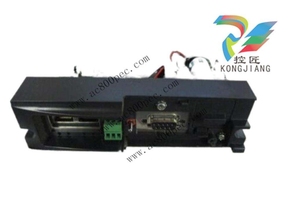
Item Status Possible Cause Controller Action What to do
BAD VERSION The Main CPU
determined that its
software is not
compatible with the
scanner module.
All associated module
diagnostics are set to
MISSING/NO COMM.
Refer to MISSING/NO
COMM diagnostic for
further details.
1. Upgrade the scanner software either
by replacing the module or doing a
code-download.
2. Update Main CPU software either by
replacing the module or doing a code
download.
RTC Status GOOD N/A N/A N/A
NOT
PROGRAMMED
RTC not programmed 1. Time and date is set to
00:00:00, January 1, 1970.
2. Associated rack monitor
block’s RACK OK pin is
turned off.
3. SYSTEM MONITOR
block’s HW OK pin is
turned off.
Program RTC.
BAD DATA Bad date and time See NOT
PROGRAMMED.
1. Program RTC.
2. Cycle power.
3. Replace CPU.
4. Replace boards in rack.
5. Replace rack.
PROGRAMMING
FAILURE
RTC failed to program See NOT
PROGRAMMED.
See BAD DATA.
READ FAILURE Unable to read RTC See NOT
PROGRAMMED.
See BAD DATA.
Comm Port
Status (Rack 1)
IO Comm
Link Status
(Rack 2-5)
Good N/A N/A N/A
Item Status Possible Cause Controller Action What to do
Data Link Failure The communications
to a particular rack is
resulting in a lot of
DLL errors.
1. Related rack monitor
block’s RACK OK pin is
turned off.
2. Depending on the
nature of the DLL errors,
the associated rack
monitor block’s module
diagnostics, and pins
could be affected.
1. Use the OI to determine which rack
is experiencing the DLL errors. Verify
that the expansion rack should be in
the configuration
2. Verify that the jumpers on the
scanner are setup for the correct rack
address.
3. If a hub is used, check that all
cables are properly connected to the
hub, proper crossover cables are
used, and that hub is powered.
4. Cycle power to the rack.
5. Cycle power to the hub.
6. Replace the HC900-C50 expansion
rack’s power supply.
7. Replace the HC900-C50 expansion
rack.
8. Replace the HC900-C50 expansion
rack’s scanner board.
9. Replace the main CPU.
Hardware Failure The power-up test of
the expansion rack
Ethernet controller
failed.
1. All rack monitor block
XIO PORT DIAG are set
to HWFAIL.
2. All rack monitor block
RACK OK pin are turned
off.
3. All modules in the
configuration have their
diagnostic set to
MOD_NOCOMM, their
rack monitor module fail
pin is turned on., and the
rack monitor block’s
RACK OK pin is turned
off.
4. ASYS block’s HW OK
pin is turned off.
5. The statuses for the AO
and AI channels that are
affected are set to
BAD_CHANNEL.
Replace main-CPU module
Port A/B Cable
Mismatch
C70R only. The I/O
cables from CPUA
and CPUB are
connected to the
wrong ports on the
I/O scanner CPU
Controller continues to run
but is not able to access
the I/O on the associated
rack
Swap the cables so that I/O A is
connected to I/O on CPUA and I/O B
is connected to I/O on CPUB
Purchase history
| User name | Member Level | Quantity | Specification | Purchase Date |
|---|
Total 0 Record
Related products

Customer Reviews
Satisfaction :
5 Stars
No evaluation information


- other
- LTI Drives
- ADLINK
- Beckhoff
- Other Brands
- AMAT
- Iba
- PEPPERL+FUCHS
- Aerotech
- WATLOW
- MAN
- ADVANCED
- Abaco
- YOKOGAWA
- KOLLMORGEN
- MEGGITT
- kong-sberg
- METSO
- Motorola
- NI
- OEMAX
- RELIANCE
- scanlab
- schneider
- uniop
- Vibro-Meter
- Honeywell
- Rolls-Royce
- MOOG
- GE
- B&R
- Woodward
- Yaskawa
- xYCOM
- Siemens
- Emerson
- HIMA
- Bently
- ZYGO
- FOXBORO
- OMACO
- PROSOFT
- ENTERASYS
- TRICONEX
- Parker
- Lenze
- KEBA
- Alstom
- CTI
- ABB
- A-B
142

-
 ADLINK PCI-9112/cPCI-9112 multifunctional acquisition card
 -
 ADLINK PCI-8102 Two Axis Pulse Motion Control Card
 -
 ADLINK PCI-9812/PCI-9810 synchronous 4-channel high-speed acquisition card
 -
 ADLINK PCI-7200/cPCI-7200 high-speed digital I/O board
 -
 ADLINK MXE-1000 series fanless embedded machine
 -
 ADLINK IMB-T10 Mini ITX Industrial Motherboard
 -
 ADLINK HSL Distributed High Speed I/O System
 -
 ADLINK PXI/DAQ/DAQe-2500 series multifunctional analog output DAQ card
 -
 ADLINK PXI/DAQ/DAQe-2200 series multifunctional data acquisition card
 -
 ADLINK ETX-AT ETX Core Computer Module
 -
 ADLINK ACL-7225 ISA 16 channel relay output+16 channel isolated digital input card
 -
 ADLINK DAQ-2000 series synchronous acquisition card
 -
 ADLINK NuPRO-E330 PICMG 1.3 full-length industrial motherboard (SHB)
 -
 ADLINK ACL-8112 series multifunctional ISA acquisition card
 -
 ADLINK USB-2405 24 bit dynamic signal acquisition module
 -
 ADLINK PXIS-3320 15 slot 6U PXI chassis
 -
 ADLINK PCIe GIE7x series acquisition card
 -
 ADLINK PCIe-7856/PCIe-7853 Distributed Motion and IO Main Controller PCIe Acquisition Card
 -
 ADLINK PCI-6308 series isolated analog output board
 -
 ADLINK PCI-7432 Isolated Digital I/O Acquisition Card
 -
 ADLINK NuPRO-E72 PICMG 1.3 Full length Industrial SHB Single Board Computer
 -
 ADLINK MXE-5400 series fanless embedded industrial computer
 -
 ADLINK M-322 Industrial ATX Motherboard
 -
 ADLINK IMB-M43H Industrial ATX Motherboard
 -
 ADLINK IMB-M42H Industrial ATX Motherboard
 -
 ADLINK i915GV-INA ATX motherboard
 -
 ADLINK ETX-NR667 Embedded ETX Standard Computer Module
 -
 ADLINK ETX-BT (PATA to SATA version) User Manual
 -
 ADLINK CM1-BT1 PC/104 Single Board Computer
 -
![ADLINK cPCI-8217 [R] 3U CompactPCI VGA/LCD Display Module](https://aosspic10001.websiteonline.cn/hkw632bc8/image/image_aJXQRn.png) ADLINK cPCI-8217 [R] 3U CompactPCI VGA/LCD Display Module
ADLINK cPCI-8217 [R] 3U CompactPCI VGA/LCD Display Module -
 ADLINK AmITX-SL-G Mini ITX Embedded Motherboard
 -
 ADLINK AmITX-AL-I ultra-thin Mini ITX industrial motherboard
 -
 ADLINK NuPRO-E315 Full length PICMG 1.3 Industrial SHB Single Board Computer
 -
 ADLINK NuPRO-842 Full length PICMG 1.0 PCI/ISA Industrial Single Board Computer
 -
 ADLINK NuPRO-900A PICMG 1.2 ePCI-X Dual Xeon Industrial System Motherboard (SHB)
 -
 ADLINK cPCI-6910 series 6U CompactPCI single board computer
 -
 ADLINK cPCI-6860A 6U CompactPCI dual core single board computer with cPCI-R6860A rear adapter board
 -
 ADLINK cPCI-8168 6U CompactPCI Eight Axis Motion Control Card
 -
 ADLINK NuPRO-E340 PICMG 1.3 Industrial SHB motherboard
 -
 ADLINK NuPRO-A40H Full length PICMG1.0 Industrial Single Board Computer (SBC)
 -
 ADLINK NuPRO-852 Full length PICMG1.0 Industrial Single Board Computer
 -
 ADLINK NuPRO-841 Full length Industrial SBC
 -
 ADLINK NuPRO-590/591/592 series Socket7 full-length industrial SBC
 -
 ADLINK MXE-5500 series fanless embedded industrial computer
 -
 ADLINK MXE-200/200i Fanless Embedded Machine
 -
 ADLINK cPCI-6770 series CompactPCI CPU board
 -
 ADLINK NuPRO-A301 standard PICMG 1.0 full-length industrial SBC single board computer
 -
 ADLINK NuPRO-965 PICMG 1.3 SHB Express Full length Industrial Motherboard
 -
 ADLINK NuPRO-935A Full length PICMG1.0 Industrial Single Board Computer
 -
 ADLINK NuPRO-865 Full length Single Board Computer
 -
 ADLINK NuPRO-840 DV/LV Full Length PICMG Industrial Single Board Computer
 -
 ADLINK NuPRO-770 series full-length industrial single board computer
 -
 ADLINK NuPRO-595 series half length Socket 7 industrial motherboard
 -
 ADLINK cPCI-6840 series 6U CompactPCI single board computer
 -
 Foxboro 43AP series pneumatic indicator controller (PSS 3-1B3 A)
 -
 ADLINK cPCI-3720 Series 3U Low Power CompactPCI Single Board Computer
 -
 ADLINK NuPRO-E47, PICMG 1.3 full-length industrial SHB system motherboard
 -
 ADLINK NuPRO-E43 PICMG 1.3 full-length system motherboard
 -
 ADLINK NuPRO-780 series full-length industrial CPU board
 -
 ADLINK cPCI-6965 series 6U CPCI single board computer
 -
 ADLINK USB/LPCI/LPCIe-3488A GPIB interface card
 -
 Rittal SK 3241.700 Blue e+Fan Filter Unit
 -
 ADLINK cPCI-8168 6U CompactPCI 8-Axis Motion Control Card
 -
 ADLINK PCIe PXIe-8638 PCIe to PXIe Bus Expansion Kit
 -
 ADLINK PCIe GIE7x series acquisition card
 -
 ADLINK PCIe-7396 96 96 channel TTL digital IO card
 -
 ADLINK PCI/MPC/PXI-8164 Three in One Motion Control Card
 -
 ADLINK PCI-8154 Four Axis Pulse Motion Control Card
 -
 ADLINK PCI-8134 Four Axis Servo/Stepper Motion Control Card
 -
 ADLINK NuPRO-E42 PICMG1.3 full-length SHB motherboard
 -
 ADLINK MXC-6600 series high-performance fanless extended industrial computer
 -
 ADLINK MXC-6000 series embedded industrial control computer
 -
 ADLINK MXC-2300 series fanless expandable embedded industrial computer
 -
 ADLINK MCM-204 Independent Ethernet DAQ User Manual
 -
 ADLINK MCM-100/102 Edge IoT Platform for Machine Condition Monitoring User’s Manual
 -
 ADLINK MXC-6400 series sixth generation Core Fanless Scalable Industrial Control Computer
 -
 ADLINK Matrix Full Series Fanless Embedded Industrial Control Computers
 -
 ADLINK GIE64+4-channel PoE Gigabit Vision Capture Card
 -
 Honeywell UMS Security System Troubleshooting Guide
 -
 Honeywell Expert Series-C I/O Module
 -
 ADLINK EOS-1200 Embedded Vision Host
 -
 ADLINK DLAP-5200 series high-performance fanless AI industrial computer
 -
 ADLINK DLAP-4000 series embedded industrial control computer
 -
 ADLINK Matrix MXC-2000 Series Fanless Industrial Control Computer Specification
 -
 ADLINK DAQ -/DAQE -/PXI-2000 Series Multi functional Synchronous Acquisition Card
 -
 ADLINK cPCI-6520 6U CompactPCI Single Board Computer
 -
 ADLINK CM1-86DX3 PC/104 Single Board Computer
 -
 Honeywell DC1000 series PID temperature controller
 -
 ALSTOM MiCOM C264 Modular Substation Controller
 -
 EMERSON AMS 2140 Mechanical Health Analyzer
 -
 ADLINK NuPRO-E320 PICMG1.3 Full length Industrial Motherboard
 -
 ADLINK NuPRO-800 Series Full length Industrial SBC User Manual
 -
 ADLINK NuPRO-598 Industrial Single Board Computer
 -
 ADLINK MXC-6300 Fanless Embedded Industrial Control Computer
 -
 ADLINK Express-BASE7 User Manual
 -
 ADLINK DLAP-211 Series Fanless Edge AI Platform Specification Manual
 -
 ADLINK PCI/LPCI/LPCIe/cPCI-723X series 32 channel isolated digital I/O card
 -
 ADLINK cPCI-6965 series 6U CompactPCI single board computer
 -
 ADLINK NuDAQ 7200 series high-speed digital I/O board
 -
 Linghua ADLINK DLAP Deep Learning Acceleration Platform Product Manual
 -
 DEIF TCM-2 thyristor control module
 -
 Installation Manual for DEIF MVR-200 Series Medium Voltage Protection Device
 -
 DEIF MDR-2 multifunctional differential relay
 -
 DEIF AOM-1 Analog Output Module
 -
 DEIF AGI 400 series industrial/marine touch screen
 -
 Installation Manual for DEIF BRW-1 Marine Wing Bridge Instrument
 -
 DEIF AGC200 Quick Start Guide
 -
 DEIF AGC Multi line 2 Generator Set ControllerProduct basic information
 -
 ABB SPA-ZC 400 Ethernet Gateway Installation and Debugging Manual
 -
 ABB REM 543/545 motor generator protection device
 -
 DEIF PPU 300 controller
 -
 DEIF Delomatic 4 Offshore/Ocean Platform Dedicated Generator Power Management System DM-4
 -
 DEIF Delomatic Modular Generator Set Integrated System
 -
 DEIF AGC-4 Mk II Generator Set Controller
 -
 DEIF AGC-4 diesel generator set integrated controller
 -
 DEIF Multi line 2 Series PPU Unit Power Management (PPM) Operation Manual
 -
 DEIF Multi line 2 V2.4X Installation Manual
 -
 Beckwith M-6280 Digital Capacitor Bank Controller
 -
 Beckwith M-3311 Transformer Protection Relay
 -
 Beckwith M-3311A Transformer Integrated Protection Device
 -
 Beckwith M-3310 Transformer Integrated Protection Device Specification
 -
 Beckwith M-0359 Syncrocloser Check Plus Application Guide for Synchronous Calibration Relay
 -
 Beckwith M-0293A On Load Tap changer Controller Application Guide
 -
 DEIF GPU-3 Synchronous/Asynchronous Generator Integrated Microcomputer Protection Controller
 -
 Installation Instructions for DEIF PPM-3
 -
 Beckwith M-3520 distributed power grid connected comprehensive protection device
 -
 Beckwith M-3430 generator comprehensive protection device
 -
 Beckwith M-2293B adapter panel

K-JIANG

Add: Jimei North Road, Jimei District, Xiamen, Fujian, China
Tell:+86-15305925923