
K-WANG
+086-15305925923
Service expert in industrial control field!


Product
Article
NameDescriptionContent
Adequate Inventory, Timely Service
pursuit of excellence


Ship control system
Equipment control system
Power monitoring system
Brand
Product parameters
- Telephone:+86-15305925923
- contacts:Mr.Wang
- Email:wang@kongjiangauto.com
Description
C70R only. The
firmware version in
the controller CPU is
not compatible with
the firmware version
in the I/O scanner
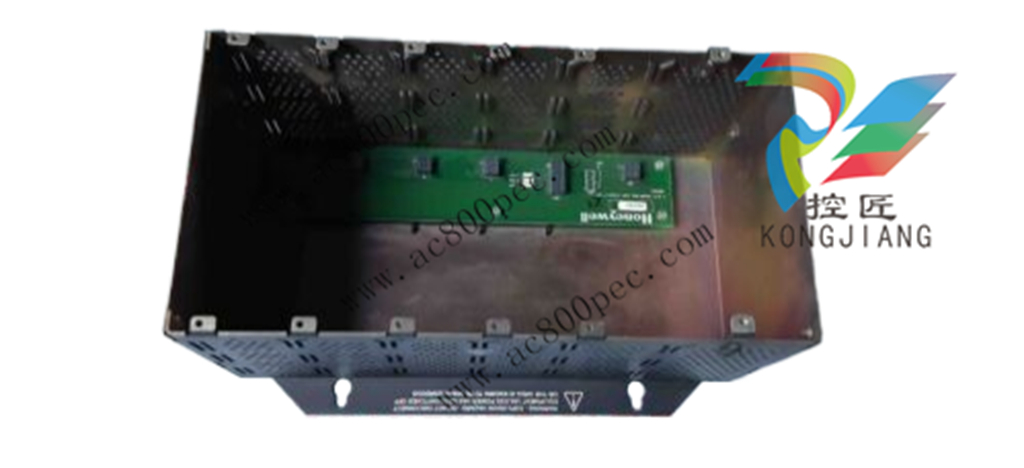
Honeywell Controller C50 CPU 900C50-0360-00
Item Status Possible Cause Controller Action What to do
Protocol Mismatch C70R only. The
firmware version in
the controller CPU is
not compatible with
the firmware version
in the I/O scanner
Controller continues to run
but is not able to access
the I/O on the associated rack
Upgrade the firmware in the CPU
and/or scanner to be compatible
versions
I/O Module Diagnostics and I/O Calibration
Select a rack to see its I/O module diagnostics. For I/O Calibration, see page 159.
Table 20 I/O module diagnostics
Item Description
MODULE Slot number in the rack.
PHYSICAL TYPE NONE
AI UNIVERSAL 8-CHAN
AI LO-LEVEL 16-CHAN
AI HI-LEVEL 8-CHAN
AO CURRENT 4-CHAN
AO VOLTAGE 4-CHAN
DI DRY-CONTACT 16-CHAN
DI 120/240 VAC 16-CHAN
DI 24 VDC 16-CHAN
DO LO-CURRENT RLY 8-CHAN
DO HI-CURRENT RLY 4-CHAN
DO 120/240 VAC 8-CHAN
DO 24 VDC 16-CHAN
AI HI-LEVEL 16-CHAN
DI 24 VDC 32-CHAN
DO 24 VDC 32-CHAN
PULSE/FREQ/QUAD 4-CHAN
HIGH LEVEL AO 8 CHANNEL
HIGH LEVEL AO 16 CHANNEL
CONFIGURED AS Analog Input, Analog Output, Digital Input, Digital Output, Pulse Frequency
Quadrature
ERROR STATUS See Table 22.
Table 21 I/O module Details
Item Description
MODULE Slot number in the rack.
PHYSICAL TYPE NONE
AI UNIVERSAL 8-CHAN
AI LO-LEVEL 16-CHAN
AI HI-LEVEL 8-CHAN
AO CURRENT 4-CHAN
AO VOLTAGE 4-CHAN
DI DRY-CONTACT 16-CHAN
DI 120/240 VAC 16-CHAN
DI 24 VDC 16-CHAN
DO LO-CURRENT RLY 8-CHAN
DO HI-CURRENT RLY 4-CHAN
DO 120/240 VAC 8-CHAN
DO 24 VDC 16-CHAN
AI HI-LEVEL 16-CHAN
DI 24 VDC 32-CHAN
DO 24 VDC 32-CHAN
PULSE/FREQ/QUAD 4-CHAN
HIGH LEVEL AO 8 CHANNEL
HIGH LEVEL AO 16 CHANNEL
PART NUMBER The re-order part number of the module.
FIRMWARE REV. Revision level of the firmware running on this module.
I/O Module Error Status
Table 22 I/O Module Error Status
Status Possible Cause Controller Action What to do
HI CJ TEMP Possible causes of
this diagnostic are:
1. One of the two CJs
on the module is indicating a
temperature reading
greater than 70 degrees C.
2. Both cold-junction
sensors are failing to convert.
3. The CJs are
converting properly,
but their differential is
greater than 10
degrees C.
1. Associated AI blocks that are configured
as T/Cs set their fail pin on, their warn pin
off, and their output pin to the failsafe value.
2. Associated AI blocks that are configured
as T/Cs set their IO status to “CJ High
Temperature” for reason 1 or “CJ Failure”
for possible causes 2 and 3.
3. Associated rack monitor block’s module
fail pin is turned on.
4. Associated rack monitor block’s RACK
OK pin is turned off.
5. Associated rack monitor block’s
HITEMP pin is turned on.
6. SYSTEM MONITOR block’s HITEMP
pin is turned on.
7. SYSTEM MONITOR block’s HW OK
pin is turned off.
1. Improve ventilation to rack
2. Replace AI module
MISMATCH The installed module
does not agree with
the module required
for the control
strategy downloaded
in the configuration file.
1. Associated blocks set their fail pin on,
their warn pin off, and their output pin to the
failsafe value.
2. Associated blocks set their IO status to
“Channel No Comm”.
3. Associated rack monitor block’s module
fail pin is turned on.
4. Associated rack monitor block’s RACK
OK pin is turned off.
5. SYSTEM MONITOR block’s HW OK
pin is turned off.
1. Verify configuration
2. Replace module with the correct one.
Status Possible Cause Controller Action What to do
MISSING/NO
COMM
Main CPU is unable
to communicate to
the module for one of
the following reasons:
1. Module is not installed
2. The module cannot
communicate with the
controller CPU or the
expansion rack CPU
because of a
backplane problem.
3. Module is on an
expansion rack and
the expansion rack
communications is failing
See MISMATCH. Action is based on the RACK STATUS
indication. If RACK STATUS is not
MODULE ERROR, then follow the
prescribed action defined for the RACK
STATUS diagnostic.
For MODULE ERROR, do the following:
1. Verify configuration
2. Install module.
BAD MODULE Module is reporting a
diagnostic condition.
See Table 23.
See MISMATCH. User should inspect the module’s status
LED to determine the nature of the
problem. Table 23 describes the user
action for the various LED diagnostics. BAD CHANNEL
See Table 24 1. Associated block sets its fail pin on, its
warn pin off, and its output pin to the
failsafe value.
2. Associated block sets its IO status as
denoted in Table 24.
3. Associated rack monitor block’s module
fail pin is turned on.
4. Associated rack monitor block’s RACK
OK pin is turned off.
5. SYSTEM MONITOR block’s HW OK
pin is turned off. See Table 24
Purchase history
| User name | Member Level | Quantity | Specification | Purchase Date |
|---|
Total 0 Record
Related products

Customer Reviews
Satisfaction :
5 Stars
No evaluation information


- other
- LTI Drives
- ADLINK
- Beckhoff
- Other Brands
- AMAT
- Iba
- PEPPERL+FUCHS
- Aerotech
- WATLOW
- MAN
- ADVANCED
- Abaco
- YOKOGAWA
- KOLLMORGEN
- MEGGITT
- kong-sberg
- METSO
- Motorola
- NI
- OEMAX
- RELIANCE
- scanlab
- schneider
- uniop
- Vibro-Meter
- Honeywell
- Rolls-Royce
- MOOG
- GE
- B&R
- Woodward
- Yaskawa
- xYCOM
- Siemens
- Emerson
- HIMA
- Bently
- ZYGO
- FOXBORO
- OMACO
- PROSOFT
- ENTERASYS
- TRICONEX
- Parker
- Lenze
- KEBA
- Alstom
- CTI
- ABB
- A-B
142

-
 ADLINK PCI-9112/cPCI-9112 multifunctional acquisition card
 -
 ADLINK PCI-8102 Two Axis Pulse Motion Control Card
 -
 ADLINK PCI-9812/PCI-9810 synchronous 4-channel high-speed acquisition card
 -
 ADLINK PCI-7200/cPCI-7200 high-speed digital I/O board
 -
 ADLINK MXE-1000 series fanless embedded machine
 -
 ADLINK IMB-T10 Mini ITX Industrial Motherboard
 -
 ADLINK HSL Distributed High Speed I/O System
 -
 ADLINK PXI/DAQ/DAQe-2500 series multifunctional analog output DAQ card
 -
 ADLINK PXI/DAQ/DAQe-2200 series multifunctional data acquisition card
 -
 ADLINK ETX-AT ETX Core Computer Module
 -
 ADLINK ACL-7225 ISA 16 channel relay output+16 channel isolated digital input card
 -
 ADLINK DAQ-2000 series synchronous acquisition card
 -
 ADLINK NuPRO-E330 PICMG 1.3 full-length industrial motherboard (SHB)
 -
 ADLINK ACL-8112 series multifunctional ISA acquisition card
 -
 ADLINK USB-2405 24 bit dynamic signal acquisition module
 -
 ADLINK PXIS-3320 15 slot 6U PXI chassis
 -
 ADLINK PCIe GIE7x series acquisition card
 -
 ADLINK PCIe-7856/PCIe-7853 Distributed Motion and IO Main Controller PCIe Acquisition Card
 -
 ADLINK PCI-6308 series isolated analog output board
 -
 ADLINK PCI-7432 Isolated Digital I/O Acquisition Card
 -
 ADLINK NuPRO-E72 PICMG 1.3 Full length Industrial SHB Single Board Computer
 -
 ADLINK MXE-5400 series fanless embedded industrial computer
 -
 ADLINK M-322 Industrial ATX Motherboard
 -
 ADLINK IMB-M43H Industrial ATX Motherboard
 -
 ADLINK IMB-M42H Industrial ATX Motherboard
 -
 ADLINK i915GV-INA ATX motherboard
 -
 ADLINK ETX-NR667 Embedded ETX Standard Computer Module
 -
 ADLINK ETX-BT (PATA to SATA version) User Manual
 -
 ADLINK CM1-BT1 PC/104 Single Board Computer
 -
![ADLINK cPCI-8217 [R] 3U CompactPCI VGA/LCD Display Module](https://aosspic10001.websiteonline.cn/hkw632bc8/image/image_aJXQRn.png) ADLINK cPCI-8217 [R] 3U CompactPCI VGA/LCD Display Module
ADLINK cPCI-8217 [R] 3U CompactPCI VGA/LCD Display Module -
 ADLINK AmITX-SL-G Mini ITX Embedded Motherboard
 -
 ADLINK AmITX-AL-I ultra-thin Mini ITX industrial motherboard
 -
 ADLINK NuPRO-E315 Full length PICMG 1.3 Industrial SHB Single Board Computer
 -
 ADLINK NuPRO-842 Full length PICMG 1.0 PCI/ISA Industrial Single Board Computer
 -
 ADLINK NuPRO-900A PICMG 1.2 ePCI-X Dual Xeon Industrial System Motherboard (SHB)
 -
 ADLINK cPCI-6910 series 6U CompactPCI single board computer
 -
 ADLINK cPCI-6860A 6U CompactPCI dual core single board computer with cPCI-R6860A rear adapter board
 -
 ADLINK cPCI-8168 6U CompactPCI Eight Axis Motion Control Card
 -
 ADLINK NuPRO-E340 PICMG 1.3 Industrial SHB motherboard
 -
 ADLINK NuPRO-A40H Full length PICMG1.0 Industrial Single Board Computer (SBC)
 -
 ADLINK NuPRO-852 Full length PICMG1.0 Industrial Single Board Computer
 -
 ADLINK NuPRO-841 Full length Industrial SBC
 -
 ADLINK NuPRO-590/591/592 series Socket7 full-length industrial SBC
 -
 ADLINK MXE-5500 series fanless embedded industrial computer
 -
 ADLINK MXE-200/200i Fanless Embedded Machine
 -
 ADLINK cPCI-6770 series CompactPCI CPU board
 -
 ADLINK NuPRO-A301 standard PICMG 1.0 full-length industrial SBC single board computer
 -
 ADLINK NuPRO-965 PICMG 1.3 SHB Express Full length Industrial Motherboard
 -
 ADLINK NuPRO-935A Full length PICMG1.0 Industrial Single Board Computer
 -
 ADLINK NuPRO-865 Full length Single Board Computer
 -
 ADLINK NuPRO-840 DV/LV Full Length PICMG Industrial Single Board Computer
 -
 ADLINK NuPRO-770 series full-length industrial single board computer
 -
 ADLINK NuPRO-595 series half length Socket 7 industrial motherboard
 -
 ADLINK cPCI-6840 series 6U CompactPCI single board computer
 -
 Foxboro 43AP series pneumatic indicator controller (PSS 3-1B3 A)
 -
 ADLINK cPCI-3720 Series 3U Low Power CompactPCI Single Board Computer
 -
 ADLINK NuPRO-E47, PICMG 1.3 full-length industrial SHB system motherboard
 -
 ADLINK NuPRO-E43 PICMG 1.3 full-length system motherboard
 -
 ADLINK NuPRO-780 series full-length industrial CPU board
 -
 ADLINK cPCI-6965 series 6U CPCI single board computer
 -
 ADLINK USB/LPCI/LPCIe-3488A GPIB interface card
 -
 Rittal SK 3241.700 Blue e+Fan Filter Unit
 -
 ADLINK cPCI-8168 6U CompactPCI 8-Axis Motion Control Card
 -
 ADLINK PCIe PXIe-8638 PCIe to PXIe Bus Expansion Kit
 -
 ADLINK PCIe GIE7x series acquisition card
 -
 ADLINK PCIe-7396 96 96 channel TTL digital IO card
 -
 ADLINK PCI/MPC/PXI-8164 Three in One Motion Control Card
 -
 ADLINK PCI-8154 Four Axis Pulse Motion Control Card
 -
 ADLINK PCI-8134 Four Axis Servo/Stepper Motion Control Card
 -
 ADLINK NuPRO-E42 PICMG1.3 full-length SHB motherboard
 -
 ADLINK MXC-6600 series high-performance fanless extended industrial computer
 -
 ADLINK MXC-6000 series embedded industrial control computer
 -
 ADLINK MXC-2300 series fanless expandable embedded industrial computer
 -
 ADLINK MCM-204 Independent Ethernet DAQ User Manual
 -
 ADLINK MCM-100/102 Edge IoT Platform for Machine Condition Monitoring User’s Manual
 -
 ADLINK MXC-6400 series sixth generation Core Fanless Scalable Industrial Control Computer
 -
 ADLINK Matrix Full Series Fanless Embedded Industrial Control Computers
 -
 ADLINK GIE64+4-channel PoE Gigabit Vision Capture Card
 -
 Honeywell UMS Security System Troubleshooting Guide
 -
 Honeywell Expert Series-C I/O Module
 -
 ADLINK EOS-1200 Embedded Vision Host
 -
 ADLINK DLAP-5200 series high-performance fanless AI industrial computer
 -
 ADLINK DLAP-4000 series embedded industrial control computer
 -
 ADLINK Matrix MXC-2000 Series Fanless Industrial Control Computer Specification
 -
 ADLINK DAQ -/DAQE -/PXI-2000 Series Multi functional Synchronous Acquisition Card
 -
 ADLINK cPCI-6520 6U CompactPCI Single Board Computer
 -
 ADLINK CM1-86DX3 PC/104 Single Board Computer
 -
 Honeywell DC1000 series PID temperature controller
 -
 ALSTOM MiCOM C264 Modular Substation Controller
 -
 EMERSON AMS 2140 Mechanical Health Analyzer
 -
 ADLINK NuPRO-E320 PICMG1.3 Full length Industrial Motherboard
 -
 ADLINK NuPRO-800 Series Full length Industrial SBC User Manual
 -
 ADLINK NuPRO-598 Industrial Single Board Computer
 -
 ADLINK MXC-6300 Fanless Embedded Industrial Control Computer
 -
 ADLINK Express-BASE7 User Manual
 -
 ADLINK DLAP-211 Series Fanless Edge AI Platform Specification Manual
 -
 ADLINK PCI/LPCI/LPCIe/cPCI-723X series 32 channel isolated digital I/O card
 -
 ADLINK cPCI-6965 series 6U CompactPCI single board computer
 -
 ADLINK NuDAQ 7200 series high-speed digital I/O board
 -
 Linghua ADLINK DLAP Deep Learning Acceleration Platform Product Manual
 -
 DEIF TCM-2 thyristor control module
 -
 Installation Manual for DEIF MVR-200 Series Medium Voltage Protection Device
 -
 DEIF MDR-2 multifunctional differential relay
 -
 DEIF AOM-1 Analog Output Module
 -
 DEIF AGI 400 series industrial/marine touch screen
 -
 Installation Manual for DEIF BRW-1 Marine Wing Bridge Instrument
 -
 DEIF AGC200 Quick Start Guide
 -
 DEIF AGC Multi line 2 Generator Set ControllerProduct basic information
 -
 ABB SPA-ZC 400 Ethernet Gateway Installation and Debugging Manual
 -
 ABB REM 543/545 motor generator protection device
 -
 DEIF PPU 300 controller
 -
 DEIF Delomatic 4 Offshore/Ocean Platform Dedicated Generator Power Management System DM-4
 -
 DEIF Delomatic Modular Generator Set Integrated System
 -
 DEIF AGC-4 Mk II Generator Set Controller
 -
 DEIF AGC-4 diesel generator set integrated controller
 -
 DEIF Multi line 2 Series PPU Unit Power Management (PPM) Operation Manual
 -
 DEIF Multi line 2 V2.4X Installation Manual
 -
 Beckwith M-6280 Digital Capacitor Bank Controller
 -
 Beckwith M-3311 Transformer Protection Relay
 -
 Beckwith M-3311A Transformer Integrated Protection Device
 -
 Beckwith M-3310 Transformer Integrated Protection Device Specification
 -
 Beckwith M-0359 Syncrocloser Check Plus Application Guide for Synchronous Calibration Relay
 -
 Beckwith M-0293A On Load Tap changer Controller Application Guide
 -
 DEIF GPU-3 Synchronous/Asynchronous Generator Integrated Microcomputer Protection Controller
 -
 Installation Instructions for DEIF PPM-3
 -
 Beckwith M-3520 distributed power grid connected comprehensive protection device
 -
 Beckwith M-3430 generator comprehensive protection device
 -
 Beckwith M-2293B adapter panel

K-JIANG

Add: Jimei North Road, Jimei District, Xiamen, Fujian, China
Tell:+86-15305925923