
K-WANG
+086-15305925923
Service expert in industrial control field!
Product
Article
NameDescriptionContent
Adequate Inventory, Timely Service
pursuit of excellence


Ship control system
Equipment control system
Power monitoring system
Brand
Product parameters
- Telephone:+86-15305925923
- contacts:Mr.Wang
- Email:wang@kongjiangauto.com
Description
Features
Provides battery backup
Enables redundant battery energy backup on the AC 800F
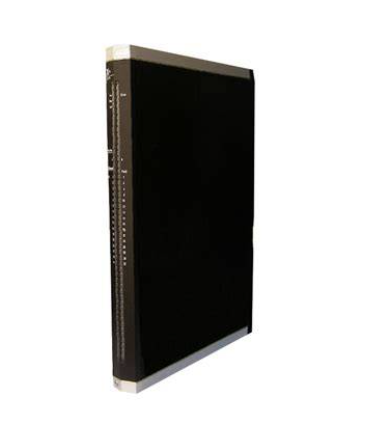
ABB Battery Module AM811F
Features
Provides battery backup
Enables redundant battery energy backup on the AC 800F
Description
The battery module provides for retention of the AC 800F RAM
data when the AC 800F is off or has no Ethernet module.
The battery module is used when the AC 800F is used as a
stand-alone device, i.e. when it has no Ethernet connection, or
when the only existing Ethernet module is to be replaced with out the AC 800F loosing its configuration data.
LED Displays
State
Off No supply power, module is isolated
Green Power supply on, module identified and
ready to operate as configured.
Orange Power supply on, module identified and ei ther:
— normal transitory state after module
startup
— configuration mode of Boot Loader
Red Module power supply is on and either:
— module not yet identified (normal for
short time, during module startup)
— error occurred during module test
Battery (PM803F)
Off AC 800F is active, AM 811F not active
=>buffering from power supply module
AC 800F is off (no watchdog of the batter ies voltage) =>buffering from battery.
Orange During battery recovery or start-up phase
Red Warning: battery low, no battery inserted,
insufficient electrical contact etc.
Green battery inserted and data protection pro vided.
Battery (PM802F)
Off Sufficient buffer battery voltage
Orange Buffer battery not found or low (insufficient
voltage).
Technical Data
Rated voltage 3.3 V / 5 V, ±3%, from CPU board
Power consumption approx. 0.28 W
Battery 3.6 V lithium battery, 950 mAh
(included in delivery)
Low battery
signaling ≤ 3.2 V
RAM and real-time-clock buffering time
PM 803F PM 802F
New battery inserted ≥ 10 days ≥ 1,5 years
After “Low” warning ≥ 5 hours ≥ 10 days
Weight approx. 0.150 kg without buffer battery
approx. 0.170 kg with buffer battery
Environmental Conditions
Permissible ambient temperature 0 °C - 60 °C
Permissible module internal temperature
0 °C - 70 °C (temperature monitoring on basic unit)
Temperature gradient In operation: 1 °C/min, according to DIN IEC 68, Part 14/EN 60068-2-14(11.99)
Transport and storage temperature
-25 °C - +85 °C
Permissible relative humidity Non-condensing, ≤ 80 % annual average
≤ 95 % for 30 days per year maximum
Degree of humidity RH-1, according to EN 61131-2: 1994 (IEC 1131-2)
Climatic category KWF according to DIN 40040 (replaced by EN 60721-3-3 and EN 61709)
3K3 according to DIN IEC 721/EN 60721-3-3
Degree of protection For basic unit with module complement: IP20
Electromagnetic Compatibility (EMC)
Complies with the protection requirements of EMI directive 89/336/EEC of May 1989 and EMVG of Nov. 1992.
Interference suppression According to EN 55022 / 4.1988
DIN VDE 0878 Part 22 / 11.89, class B
Noise immunity Basic standard: EN 50082, VDE 0839 - Part 82-2, EN 61000-6-2
Tested according to EN61000-4; VDE 0847
• Parts 1 to 6,8,11, Degree 3, are met with shielded communication cables
• The industrial standard to NAMUR 21 / 8.98 is met
Electrical Protection
Safety class II
Overvoltage category II for all connectors, pollution degree 2
Designed according to IEC 1010-1 (1990 - 09); EN 61010-1 / 3.94 or
DIN/EN 61010 - Part 1 / 3.94 (VDE 0411 - Part 1),
CSAC 22.2, No. 1010-1 and No. 213 (Class I, Div 2),
SIQ (CB Scheme 97NK2421),
CSA/NTRL.
Module supply power Extra low voltage with protective separation from other circuits which may be grounded
according to DIN VDE 0100, Part 410-1.97/IEC 60364-4-41/10.92
Power supply SA 801F, SA 811F Safety isolating transformer according to DIN VDE 0551, Part 1 (9.95); EN 60742
Optocoupler for protective separation against electrical shock
(German standard VDE 0884 / 8.87)
Power supply SD 802F, SD 812F No elec. separation!
Shock and Vibration Data
Tested according to DIN IEC 68, Part 2-6, 2-27/EN 60068-2-6, 2-27 (11.99)
Transport
Shock 30 g/11 ms/ 3 times to each axis
Max. values for the individual modules. The values are valid for correct mounted modules.
In operation
Vibration, 3x5 cycles 2 g/0.15 mm/5 - 150 Hz
The following table lists the anticipated power dissipation (heat
dissipation) of individual AC 800F modules.
The data for the modules contain the combined power con sumption from internal and external supply sources. For de tailed information see the Mounting and Installation Instruc tions, AC 800F manual.
Module Max. Power Dissipation
Basic unit PM 802F
with power supply SA 801F
with power supply SD 802F
20.8 W
10.8 W
Basic unit PM 803F
with power supply SA 811F
with power supply SD 812F
26.8 W
13.8 W
Ethernet module EI 801F
EI 811F
2.8 W
2.0 W
Ethernet module EI 802F
Without transceiver supply
With transceiver supply
3.0 W
6.2 W
Ethernet module EI 812F
Without transceiver supply
With transceiver supply
2.3 W
4.9 W
Ethernet module EI 803F
EI 813F
1.8 W
1.2 W
CAN-module FI 810F 2.6 W
Serial module FI 820F 2.6 W
PROFIBUS module FI 830F 2.8 W
FF/HSE module FI 840F 2.1 W
Battery module AM 801F
AM 811F
0.25 W
0.28 W
Purchase history
| User name | Member Level | Quantity | Specification | Purchase Date |
|---|
Total 0 Record
Related products
Customer Reviews
Satisfaction :
5 Stars
No evaluation information


