
K-WANG
+086-15305925923
Service expert in industrial control field!


Product
Article
NameDescriptionContent
Adequate Inventory, Timely Service
pursuit of excellence


Ship control system
Equipment control system
Power monitoring system
Brand
Product parameters
- Telephone:+86-15305925923
- contacts:Mr.Wang
- Email:wang@kongjiangauto.com
Description
The drive and adjoining equipment must be properly earthed.
Do not attempt any work on a powered drive. After switching off the
mains, always allow the intermediate circuit capacitors 5 minutes to
discharge before working on the frequency converter, the motor or the
motor cable. It is good practice to check (with a voltage indicating
instrument) that the drive is in fact discharged before beginning work.
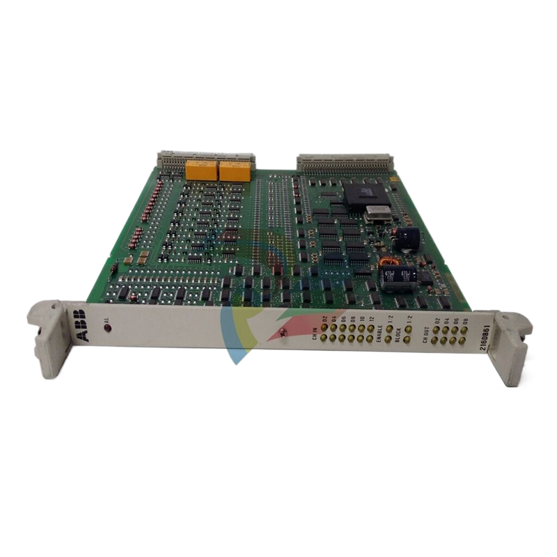
ABB NTAC-0X Pulse Encoder Interface Module
Overview This chapter contains a description of the NTAC-0x/NDIO-0x/NAIO-0x
Installation and Start-up Guide.
Intended Audience The Guide is intended for people who are responsible for installing,
commissioning and servicing the pulse encoder interface (NTAC) or I/O
extension modules (NDIO, NAIO) of ACS 600 frequency converters.
The user is expected to have a basic knowledge of electrical
fundamentals, electrical wiring practices and the ACS 600.
Applicability This Guide is applicable to the following module revisions:
• NTAC-02 revision C or later
(Refer to Appendix C for information on earlier revisions.)
• NDIO-02 revision A or later
(Refer to Appendix D for information on earlier revisions.)
• NAIO-03 revision A or later
(Refer to Appendix E for information on earlier revisions.)
What This Guide
Contains
The installation and start-up of the Pulse Encoder Interface Module,
the Digital I/O Extension Module and the Analogue I/O Extension
Module are introduced in this Guide.
Safety Instructions are placed in the first few pages of this Guide.
Safety Instructions describe the formats for various warnings and
notations used within this Guide. This chapter also states the safety
instructions which apply to the installation and operation of the option
modules.
Chapter 1 – Introduction to This Guide contains a short description
of the Guide and a list of related publications.
Chapter 2 – Overview contains a description of the Pulse Encoder
Interface Module and the I/O Extension Modules, a delivery checklist
and warranty information.
Chapter 3 – Installation contains instructions for module hardware
settings, mounting, cabling and programming.
Appendix A contains Technical Data.
Appendix B – Ambient Conditions lists the requirements for ambient
conditions during transportation, storage and use of the NTAC-0x/
NDIO-0x/NAIO-0x module.
Appendix C – NTAC-01 Information includes information on the
earlier NTAC module type (NTAC-01) for reference.
Chapter 1 – Introduction to This Guide
1-2 NTAC-0x/NDIO-0x/NAIO-0x Installation and Start-up Guide
Appendix D – NDIO-01 Information includes information on the
earlier NDIO module type (NDIO-01) for reference.
Appendix E – NAIO-01/02 Information includes information on the
earlier NAIO module types (NAIO-01 and NAIO-02) for reference.
Terms Used in
This Guide
NAIO Module The NAIO (Analogue I/O Extension Module) is an optional device for
ACS 600 frequency converters. The module offers two current or
voltage inputs and two current outputs.
NAMC Board The NAMC is the Application and Motor Control Board of the ACS 600.
There are different types of NAMC, e.g. NAMC-03 and NAMC-11.
NDCO Board The NDCO (DDCS Communication Option) series includes optional
communication boards for installation on top of the NAMC-11.
NDIO Module The NDIO (Digital I/O Extension Module) is an optional device for
ACS 600 frequency converters. The module offers two digital inputs
and two relay outputs.
NIOC Board The NIOC is the standard I/O interface of the ACS 600. It connects the
drive to the external control circuits.
NTAC Module The NTAC (Pulse Encoder Interface Module) is an optional device for
ACS 600 frequency converters. The module offers an interface for a
digital pulse encoder connection.
Overview This chapter contains a description of the I/O Extension Link, the Pulse
Encoder Interface Module, the I/O Extension Modules, and information
on warranty.
The I/O Extension
Link
All the Pulse Encoder Interface Module (NTAC) and I/O Extension
Modules (NDIO and NAIO) are connected to the frequency converter
via an optical DDCS-protocol communication link. The modules,
together with the NIOC Standard I/O Board, are usually connected in a
ring on Channel CH1 of the NAMC (Application and Motor Control
Board). The NAMC board acts as the master, polling the other stations
cyclically. The modules respond to the master’s enquiries.
Each device on the DDCS link has an individual node number. The
modules are numbered by setting the DIP switches located inside the
module enclosure. (The address of the NIOC board is fixed to 1.)
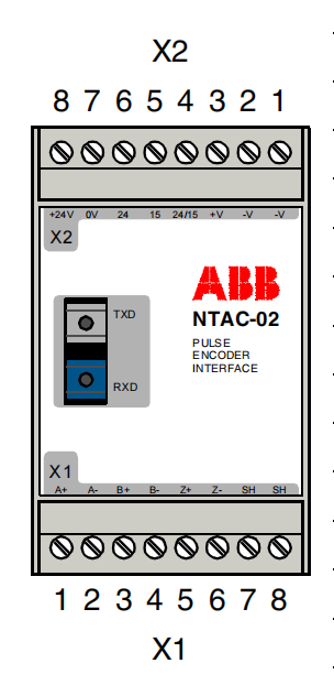
NTAC-02 Pulse
Encoder Interface
Module
The Pulse Encoder Interface Module (NTAC) offers an interface for a
digital pulse encoder connection. A pulse encoder should be used if
accurate speed or position (angle) feedback from the motor shaft is
required.
Delivery Check The package contains:
• NTAC-02 module
• three pairs of fibre optic cables (120/370/2000 mm)
• two jumper bridges (for encoder voltage selection)
• mounting rail (DIN 50022, 35 × 7.5 mm, length 45 mm)
• This manual, the NTAC-0x/NDIO-0x/NAIO-0x Installation and
Start-up Guide.
Compatibility The NTAC-02 is compatible with the following application programs:
• ACS 600 Standard Application Program version 5.0 or later
• ACS 600 System Application Program version 4.2 or later
• ACS 600 Crane Drive Application Program version 5.0 or later
• ACS 600 Application Program Template (all versions).
Encoder
Recommendation
Leine & Linde 18690010, Hübner POG 10 or equivalent:
• 90° (electrical) phase shift between channels 1 and 2
• Recommended output sinking/sourcing capability: 40 mA.
NDIO-02 Digital I/O
Extension Module
The Digital I/O Extension Module (NDIO) offers two digital inputs
(24 to 250 V d.c., or 110 to 230 V a.c.) and two relay outputs
(2000 VA/250 V a.c. or 8 A/24 V d.c.).
Delivery Check The option package contains:
• NDIO-02 module
• three pairs of fibre optic cables (120/370/2000 mm)
• mounting rail (DIN 50022, 35 × 7.5 mm, length 45 mm)
• This manual, the NTAC-0x/NDIO-0x/NAIO-0x Installation and
Start-up Guide.
Compatibility The NDIO-02 is compatible with the following application programs:
• ACS 600 Standard Application Program version 2.8 or later
• ACS 600 System Application Program version 4.2 or later
• ACS 600 Crane Drive Application Program version 5.0 or later
• ACS 600 Application Program Template (all versions).
NAIO-03 Analogue I/O
Extension Module
The Analogue I/O Extension Module (NAIO) offers two bipolar current
(±0(4) to 20 mA) or voltage (±0(2) to 10 V, or ±0 to 2 V) inputs and two
unipolar current (0(4) to 20 mA) outputs. The signal resolution (12 bits)
is better than that of the standard analogue I/O.
Delivery Check The option package contains:
• NAIO-03 module
• three pairs of fibre optic cables (120/370/2000 mm)
• mounting rail (DIN 50022, 35 × 7.5 mm, length 45 mm)
• This manual, the NTAC-0x/NDIO-0x/NAIO-0x Installation and
Start-up Guide.
Compatibility The NAIO-03 is compatible with the following application programs:
• ACS 600 Standard Application Program version 2.8 or later
• ACS 600 System Application Program version 4.2 or later
• ACS 600 Crane Drive Application Program version 5.0 or later
• ACS 600 Application Program Template (all versions).
Warranty See the Hardware Manual of the drive for information on warranty
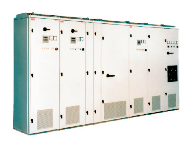
ACS 600 Connection
General The modules are connected to the drive (NAMC/NDCO board) using
the fibre optic cables included in the module package. Observe the
connector colour coding: blue connectors should go to blue receivers
(RXD), grey (or black) connectors to grey transmitters (TXD). Multiple
modules on the same channel are connected in a ring.
The fibre optic cables must be handled with care. The maximum long term tensile load is 1 N and the minimum short-term bend radius is
25 mm. The ends of the fibre must not be touched as optical fibres are
sensitive to dirt. Grommets should be used at cable lead-throughs.
Terminals The terminals which the NTAC-02, NDIO-02 and NAIO-03 modules are
connected to are given in the table below.
Figure 3-3 Connecting the modules to the ACS 600. The picture shows
two modules on Channel CH1; the terminals may vary according to the
application program used. Refer to the table above and the relevant
Firmware Manual.
Module Application Program Board Channel Terminals
NTAC-02
Standard, V5.0 or later NDCO (Optional) CH2 V17, V18
Standard, V5.0 or later
with Master/Follower Macro NAMC CH1 V15, V16
System NAMC CH1 V15, V16
Crane, V5.0 or later NAMC CH1 V15, V16
NDIO-02
NAIO-03 (all) NAMC CH1 V15, V16
Purchase history
| User name | Member Level | Quantity | Specification | Purchase Date |
|---|
Total 0 Record
Related products

Customer Reviews
Satisfaction :
5 Stars
No evaluation information


- LTI Drives
- other
- Other Brands
- AMAT
- Iba
- PEPPERL+FUCHS
- Aerotech
- WATLOW
- MAN
- ADVANCED
- Abaco
- YOKOGAWA
- KOLLMORGEN
- MEGGITT
- kong-sberg
- METSO
- Motorola
- NI
- OEMAX
- RELIANCE
- scanlab
- schneider
- uniop
- Vibro-Meter
- Honeywell
- Rolls-Royce
- MOOG
- GE
- B&R
- Woodward
- Yaskawa
- xYCOM
- Siemens
- Emerson
- HIMA
- Bently
- ZYGO
- FOXBORO
- OMACO
- PROSOFT
- ENTERASYS
- TRICONEX
- Parker
- Lenze
- KEBA
- Alstom
- CTI
- ABB
- A-B
172

-
 Basler DGC-2020 Digital Generator Set Controller
 -
 Basler MVC-300 Electronic Manual Excitation Controller
 -
 Basler MVC-104/MVC-108/MVC-232 manual excitation controller
 -
 Basler SSR32-12/SSR63-12/SSR125-12 Static Excitation Voltage Regulator
 -
 Basler SR4A/SR8A Analog Excitation Voltage Regulator
 -
 Basler BE2000E Digital Excitation Voltage Regulator
 -
 Basler DECS-2100 Digital Excitation System
 -
 Basler BE1-851 Overcurrent Protection Device Manual
 -
 Basler APR 63-5 Voltage Regulator
 -
 Basler BE1-FLEX Integrated Protection Control System
 -
 Basler BE1-700V digital voltage protection relay
 -
 Basler BE1-87B high impedance bus differential relay
 -
 Basler BE1-40Q demagnetization relay
 -
 Basler BE1-60 Voltage Balance Relay
 -
 Basler BE1-47N negative sequence voltage phase sequence relay
 -
 Basler BE1-81O/U digital frequency relay
 -
 Basler BE1-11f Feedline Integrated Protection Device Manual
 -
 Basler DECS-250 Digital Excitation Control System
 -
 Basler DECS-100 Digital Excitation Control System
 -
 Basler BE1-BPR Circuit Breaker Protection Relay
 -
 Basler BE1-50/51B-255 overcurrent relay
 -
 Basler BE1-25 synchronous check relay
 -
 Basler BE1-51 microcomputer time limited overcurrent relay
 -
 Basler DECS-300 Digital Excitation Control System
 -
 Mitsubishi MELSEC-F FX series programmable controllers
 -
 Hirschmann cSCALE Mobile Machinery Modular Controller
 -
 Hirschmann OZD Profi G12DU/G12DK/G12DE ATEX1 PROFIBUS Fiber Optic Repeater Manual
 -
 Hirschmann OCTOPUS OS20/OS24 Network Managed IP65/IP67 Industrial Switch Installation Manual
 -
 Hirschmann RS20/RS22/RS30/RS32/RS40 Series Industrial Rail Switch Installation Manual
 -
 Hirschmann EAGLE One Industrial Ethernet Firewall Installation Manual
 -
 Hirschmann MACH102 Series Industrial Switch Installation Manual
 -
 Hirschmann MS20/MS30 Modular Industrial Switch Installation Manual
 -
 Hirschmann BRS20/22/30/32/40/42/50/52 Series BOBCAT Industrial Rail Switch Installation Manual
 -
 Hirschmann RSB20 Basic Series Industrial Rail Switch Installation Manual
 -
 Hirschmann RS20 Basic Series Industrial Ethernet DIN-Rail Switches
 -
 BECKHOFF EP20xx/EP28xx IP67 EtherCAT Box Digital Output Module
 -
 BECKHOFF EL5102 Incremental Encoder Terminal Manual
 -
 BECKHOFF CU8803-000x CP Link4 Launch Box Operation Manual
 -
 Beckhoff CU20xx/CU22xx Industrial Unmanned Switch Manual
 -
 BECKHOFF AMP8000 Distributed Servo System Operation Manual
 -
 BECKHOFF EL2911/EL2911-2200 TwinSAFE Safety Potential Supply Terminal Manual
 -
 BECKHOFF EL600x/EL602x series EtherCAT serial port terminal module
 -
 BECKHOFF CP6700-0001-0050/0060 Integrated Machine Manual
 -
 BECKHOFF CP70xx Series Control Panel Installation and Operation Manual
 -
 BECKHOFF CP29xx Cabinet Mounted Industrial Touch Panel Official Operation Manual
 -
 Beckhoff C6650-0060 Control Cabinet Industrial PC
 -
 Beckhoff BK series K-bus to EtherCAT coupler
 -
 Beckhoff CX20x0 Series Embedded Industrial Control Computer Manual
 -
 Beckhoff CP77xx Series Industrial Panel PC Installation and Operation Manual
 -
 Beckhoff EL41xx Series 16 Bit Analog Output Terminal Manual
 -
 Beckhoff C63xx-0020 series control cabinet industrial PC
 -
 Beckhoff C6920-0060 Control Cabinet Industrial PC
 -
 Beckhoff CU8800-0010 USB transmitter extender (TX)
 -
 Beckhoff AX2000 series digital servo amplifier
 -
 Beckhoff AX8000 Modular Multi Axis Servo System
 -
 Beckhoff CP27xx Embedded Panel PC User Manual
 -
 Beckhoff CP69xx Industrial Embedded Control Panel
 -
 Beckhoff CP60xx Embedded Industrial Control Panel
 -
 Beckhoff CP72xx series panel PC official installation, operation, configuration, maintenance, and troubleshooting
 -
 Installation and Operation of Beckhoff CP78xx Series Control Panel
 -
 Beckhoff CP39xx series industrial touch control panel
 -
 Beckhoff CX8110 Embedded Industrial PC
 -
 Beckhoff CX50x0 series DIN rail embedded industrial PC
 -
 Beckhoff CP62xx series embedded panel PC
 -
 BECKHOFF C6030 Compact Industrial PC
 -
 UniOP ePAD32B/ePAD33B/ePAD33BT Industrial HMI
 -
 UniOP ePAD05&ePAD06 Industrial HMI
 -
 UniOP ePAD03/ePAD04 entry-level HMI
 -
 UniOP CP01R-04 Compact Industrial HMI
 -
UniOP BKDR-16 Industrial Human Machine Interface
-
 Beckwith M-3425A Generator Integrated Protection Relay
 -
 Basler DECS-200 Digital Excitation Control System
 -
 Basler DECS-250 Digital Excitation Control System Manual
 -
 HA-800 series AC servo drive
 -
 JUMO dTRANS p35 Pressure Sensor Operation Manual with IO Link Interface
 -
 KEBA XE 020 RFID Module
 -
 Honeywell SmartLine series transmitters
 -
 Eaton CROUSE-HINDS MTL MA30 RF and Surge Protector Operation Manual
 -
 Beckhoff EL31xx Series 16 Bit EtherCAT Analog Input Terminal Manual
 -
 BECKHOFF AX5000 series EtherCAT servo drive
 -
 BECKHOFF EL30xx Series 12 Bit Analog Input Terminal Manual
 -
 Beckhoff EL70x7 series stepper motor EtherCAT terminal manual
 -
 BECKHOFF CX52x0 Series Embedded Industrial PC Hardware Manual
 -
 BECKHOFF CX9000/CX9010 series embedded controllers
 -
 BECKHOFF AM8000/AM8500 Series Synchronous Servo Motor Operation Manual
 -
 BECKHOFF EL9xxx series EtherCAT system terminal
 -
 BECKHOFF EK110x/EK15xx series EtherCAT bus coupler
 -
 BECKHOFF CX51x0 Series Embedded PC Hardware Manual
 -
 BECKHOFF CX2100-0014 Embedded Power Unit User Manual
 -
 BECKHOFF CX1000 Series Modular Embedded Industrial PC Hardware Manual
 -
 BECKHOFF CP69xx series embedded industrial control panel usage instructions
 -
 Beckhoff C6030-0080 ultra compact industrial PC
 -
 IFM O3D series time-of-flight 3D industrial sensor usage instructions
 -
 Allen Bradley Guardmaster 440R series safety relay
 -
 OMRON SYSMAC CS1 Rack mounted Large and Medium sized PLC Selection
 -
 GE Multilin EPM9900P high-precision power quality analyzer
 -
 Automotive LC-4 series brushless DC driver
 -
 Doric NC500 Neuroscience Acquisition Host
 -
 Honeywell X-DCS2000/EN DIGITAL INTEGRATED SYSTEM MANAGER SYSTEM MANAGER
 -
 Kollmorgen SERVOSTAR600 (601~620) servo drive
 -
 ABB Totalflow X series differential pressure flow computer
 -
 ABB ACS6000 medium voltage frequency converter
 -
 OMRON NX502 model Sysmac platform machine controller hardware usage instructions
 -
 OMRON NX102 model hardware usage instructions
 -
 OMRON C200HX/HG/HE series rack mounted medium-sized PLC operating instructions
 -
 Azbil SDC35/SDC36 single circuit temperature controller
 -
 MITSUBISHI ELECTRIC HIGH PERFORMANCE, COST EFFICIENT GT25 SERIES
 -
 Eurotherm Mini8 Modular Temperature Control Controller
 -
 KEYENCE GC-1000/GC-1000R Safety Controller
 -
 SICK RLY3-EMSS300 safety relay
 -
 Siemens SIRIUS 3SK2 safety relay
 -
 Nordson DAGE4000 Bond Tensile Tester
 -
 Operation and Maintenance Instructions for HMS Anybus Communicator Communication Gateway
 -
 Allen Bradley 800T/800H 30mm button and indicator light
 -
 Schneider Modicon M340 Medium PAC/PLC Selection and Specifications
 -
 Kepco BOP series four quadrant bipolar power supply
 -
 Siemens SIPROTEC 5 Series Relay Protection and Automation Equipment
 -
 Banner XS/SC26&SC10-2 Safety Controller
 -
 Allen Bradley MicroLogix 1500 Programmable Controller
 -
 EOCR-PMZ (panel embedded) and EOCR-PFZ (embedded) motor comprehensive protector
 -
 Microchip PIC12F/PIC16F182X series 8-bit low pin count microcontroller
 -
 FANUC α iS/α iF/β iS series servo parameters
 -
 Mitsubishi Electric GOT2000 Series GT23 Touchscreen (HMI) General Instructions
 -
 MITSUBISHI ELECTRIC GT27 series high-end multi touch advanced HMI (touch screen)
 -
 Siemens SIMATIC ET 200M Distributed I/O System
 -
 Lenze 8200 Vector Series Vector Inverter
 -
 Siemens SIMOVERT MASTERDRIVES Vector Control (VC) Inverter Operating Instructions
 -
 FANUC I/O Unit MODEL A Connection and Maintenance

K-JIANG

Add: Jimei North Road, Jimei District, Xiamen, Fujian, China
Tell:+86-15305925923