
K-WANG


- Telephone:+86-15305925923
- contacts:Mr.Wang
- Email:wang@kongjiangauto.com
The commissioning personnel must have a basic knowledge of handling electronic
equipment. The commissioning and maintenance personnel must be well experienced
in using protection equipment, test equipment, protection functions and the
configured functional logics in the IED.
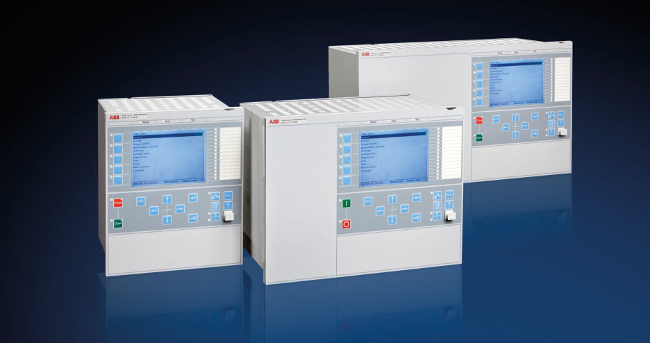
ABB RED670 1MRK004810 Line differential protection
The engineering manual contains instructions on how to engineer the IEDs using the
various tools available within the PCM600 software. The manual provides
instructions on how to set up a PCM600 project and insert IEDs to the project
structure. The manual also recommends a sequence for the engineering of protection
and control functions, LHMI functions as well as communication engineering for IEC
60870-5-103, IEC 61850 and DNP3.
The installation manual contains instructions on how to install the IED. The manual
provides procedures for mechanical and electrical installation. The chapters are
organized in the chronological order in which the IED should be installed.
The commissioning manual contains instructions on how to commission the IED. The
manual can also be used by system engineers and maintenance personnel for
assistance during the testing phase. The manual provides procedures for the checking
of external circuitry and energizing the IED, parameter setting and configuration as
well as verifying settings by secondary injection. The manual describes the process of
testing an IED in a substation which is not in service. The chapters are organized in the
chronological order in which the IED should be commissioned. The relevant
procedures may be followed also during the service and maintenance activities.
The operation manual contains instructions on how to operate the IED once it has been
commissioned. The manual provides instructions for the monitoring, controlling and
setting of the IED. The manual also describes how to identify disturbances and how to
view calculated and measured power grid data to determine the cause of a fault.
The application manual contains application descriptions and setting guidelines
sorted per function. The manual can be used to find out when and for what purpose a
typical protection function can be used. The manual can also provide assistance for
calculating settings.
The technical manual contains application and functionality descriptions and lists
function blocks, logic diagrams, input and output signals, setting parameters and
technical data, sorted per function. The manual can be used as a technical reference
during the engineering phase, installation and commissioning phase, and during
normal service.
The communication protocol manual describes the communication protocols
supported by the IED. The manual concentrates on the vendor-specific
implementations.
The point list manual describes the outlook and properties of the data points specific
to the IED. The manual should be used in conjunction with the corresponding
communication protocol manual.
The cyber security deployment guideline describes the process for handling cyber
security when communicating with the IED. Certification, Authorization with role
based access control, and product engineering for cyber security related events are
described and sorted by function. The guideline can be used as a technical reference
during the engineering phase, installation and commissioning phase, and during
normal service.
| Documents related to RED670 | Identify number |
|---|---|
| Application manual | 1MRK 505 307-UEN |
| Commissioning manual | 1MRK 505 309-UEN |
| Product guide | 1MRK 505 310-BEN |
| Technical manual | 1MRK 505 308-UEN |
| Type test certificate | 1MRK 505 310-TEN |
The caution icon indicates important information or warning related
to the concept discussed in the text. It might indicate the presence of
a hazard which could result in corruption of software or damage to
equipment or property.
The information icon alerts the reader of important facts and
conditions.
The tip icon indicates advice on, for example, how to design your
project or how to use a certain function.
Although warning hazards are related to personal injury, it is necessary to understand
that under certain operational conditions, operation of damaged equipment may result
in degraded process performance leading to personal injury or death. It is important
that the user fully complies with all warning and cautionary notices.
1.4.2 Document conventions
• Abbreviations and acronyms in this manual are spelled out in the glossary. The
glossary also contains definitions of important terms.
• Push button navigation in the LHMI menu structure is presented by using the
push button icons.
For example, to navigate between the options, use and .
• HMI menu paths are presented in bold.
For example, select Main menu/Settings.
• LHMI messages are shown in Courier font.
For example, to save the changes in non-volatile memory, select Yes and press
.
• Parameter names are shown in italics.
For example, the function can be enabled and disabled with the Operation setting.
• Each function block symbol shows the available input/output signal.
• the character ^ in front of an input/output signal name indicates that the
signal name may be customized using the PCM600 software.
• the character * after an input signal name indicates that the signal must be
connected to another function block in the application configuration to
achieve a valid application configuration.
• Logic diagrams describe the signal logic inside the function block and are
bordered by dashed lines.
Symbols on the product
All warnings must be observed.
Read the entire manual before doing installation or any maintenance
work on the product. All warnings must be observed.
Class 1 Laser product. Take adequate measures to protect your eyes
and do not view directly with optical instruments.
Do not touch the unit in operation. The installation shall take into
account the worst case temperature.
2.2 Warnings
Observe the warnings during all types of work related to the product.
Only electrically skilled persons with the proper authorization and
knowledge of any safety hazards are allowed to carry out the electrical
installation.
National and local electrical safety regulations must always be
followed. Working in a high voltage environment requires serious
approach to avoid human injuries and damage to equipment.
Do not touch circuitry during operation. Potentially lethal voltages
and currents are present.
Always use suitable isolated test pins when measuring signals in open
circuitry. Potentially lethal voltages and currents are present.
Never connect or disconnect a wire and/or a connector to or from a
IED during normal operation. Hazardous voltages and currents are
present that may be lethal. Operation may be disrupted and IED and
measuring circuitry may be damaged.
Dangerous voltages can occur on the connectors, even though the
auxiliary voltage has been disconnected.
Always connect the IED to protective earth, regardless of the
operating conditions. This also applies to special occasions such as
bench testing, demonstrations and off-site configuration. This is class
1 equipment that shall be earthed.
Never disconnect the secondary connection of current transformer
circuit without short-circuiting the transformer’s secondary winding.
Operating a current transformer with the secondary winding open will
cause a massive potential build-up that may damage the transformer
and may cause injuries to humans.
Never remove any screw from a powered IED or from a IED
connected to powered circuitry. Potentially lethal voltages and
currents are present.
Take adequate measures to protect the eyes. Never look into the laser
beam.
The IED with accessories should be mounted in a cubicle in a
restricted access area within a power station, substation or industrial
or retail environment.
| 670 series manuals | Identify number |
|---|---|
| Operation manual | 1MRK 500 118-UEN |
| Engineering manual | 1MRK 511 308-UEN |
| Installation manual | 1MRK 514 019-UEN |
| Communication protocol manual, IEC 60870-5-103 | 1MRK 511 304-UEN |
| Communication protocol manual, IEC 61850 Edition 1 | 1MRK 511 302-UEN |
| Communication protocol manual, IEC 61850 Edition 2 | 1MRK 511 303-UEN |
| Communication protocol manual, LON | 1MRK 511 305-UEN |
| Communication protocol manual, SPA | 1MRK 511 306-UEN |
| Accessories guide | 1MRK 514 012-BEN |
| Cyber security deployment guideline | 1MRK 511 309-UEN |
| Connection and Installation components | 1MRK 513 003-BEN |
| Test system, COMBITEST | 1MRK 512 001-BEN |
Whenever changes are made in the IED, measures should be taken to
avoid inadvertent tripping.
The IED contains components which are sensitive to electrostatic
discharge. ESD precautions shall always be observed prior to
touching components.
Always transport PCBs (modules) using certified conductive bags.
Do not connect live wires to the IED. Internal circuitry may be
damaged
Always use a conductive wrist strap connected to protective earth
when replacing modules. Electrostatic discharge (ESD) may damage
the module and IED circuitry.
Take care to avoid electrical shock during installation and
commissioning.
Changing the active setting group will inevitably change the IEDs
operation. Be careful and check regulations before making the
change.
| User name | Member Level | Quantity | Specification | Purchase Date |
|---|


- other
- ADLINK
- LTI Drives
- Other Brands
- AMAT
- Iba
- PEPPERL+FUCHS
- Aerotech
- WATLOW
- MAN
- ADVANCED
- Abaco
- YOKOGAWA
- KOLLMORGEN
- MEGGITT
- kong-sberg
- METSO
- Motorola
- NI
- OEMAX
- RELIANCE
- scanlab
- schneider
- uniop
- Vibro-Meter
- Honeywell
- Rolls-Royce
- MOOG
- GE
- B&R
- Woodward
- Yaskawa
- xYCOM
- Siemens
- Emerson
- HIMA
- Bently
- ZYGO
- FOXBORO
- OMACO
- PROSOFT
- ENTERASYS
- TRICONEX
- Parker
- Lenze
- KEBA
- Alstom
- CTI
- ABB
- A-B

-
 Beckwith M-3311A Transformer Integrated Protection Device
 -
 Beckwith M-3425A Generator Integrated Protection Device Manual
 -
 Basler BE1-27/BE1-59/BE1-27/59 undervoltage/overvoltage relay
 -
 Basler AVC63-12/AVC125-10 excitation voltage regulator
 -
 Basler L301kc Color Three Line Array Camera Operation Manual
 -
 Basler CBS 212A Current Enhanced Excitation System
 -
 Basler BE3-25 synchronous check relay
 -
 Operation Manual for Basler BE1-32R/BE1-32O/U Direction Power Relay
 -
 Basler Electric PRS-250 Veri Sync Synchronous Relay
 -
 Basler Pilot Series Area Array Industrial Camera piA2400-17gc
 -
 Basler BE1-11g comprehensive protection device for generator
 -
 Basler VR63-4C/UL Analog Excitation Voltage Regulator
 -
 Basler BE1-DFPR distribution feeder protection relay
 -
 Basler CBS310/CBS320 current strong excitation system
 -
 Basler UFOV250A/UFOV260A Low Frequency Overvoltage Module
 -
 Basler MVC104/MVC108/MVC232 manual voltage control device
 -
 Basler XR2002/XR2002F PMG excitation regulator
 -
 Basler DECS-400 Digital Excitation Control System
 -
 Basler DGC-2020 Digital Generator Set Controller
 -
 Basler MVC-300 Electronic Manual Excitation Controller
 -
 Basler MVC-104/MVC-108/MVC-232 manual excitation controller
 -
 Basler SSR32-12/SSR63-12/SSR125-12 Static Excitation Voltage Regulator
 -
 Basler SR4A/SR8A Analog Excitation Voltage Regulator
 -
 Basler BE2000E Digital Excitation Voltage Regulator
 -
 Basler DECS-2100 Digital Excitation System
 -
 Basler BE1-851 Overcurrent Protection Device Manual
 -
 Basler APR 63-5 Voltage Regulator
 -
 Basler BE1-FLEX Integrated Protection Control System
 -
 Basler BE1-700V digital voltage protection relay
 -
 Basler BE1-87B high impedance bus differential relay
 -
 Basler BE1-40Q demagnetization relay
 -
 Basler BE1-60 Voltage Balance Relay
 -
 Basler BE1-47N negative sequence voltage phase sequence relay
 -
 Basler BE1-81O/U digital frequency relay
 -
 Basler BE1-11f Feedline Integrated Protection Device Manual
 -
 Basler DECS-250 Digital Excitation Control System
 -
 Basler DECS-100 Digital Excitation Control System
 -
 Basler BE1-BPR Circuit Breaker Protection Relay
 -
 Basler BE1-50/51B-255 overcurrent relay
 -
 Basler BE1-25 synchronous check relay
 -
 Basler BE1-51 microcomputer time limited overcurrent relay
 -
 Basler DECS-300 Digital Excitation Control System
 -
 Mitsubishi MELSEC-F FX series programmable controllers
 -
 Hirschmann cSCALE Mobile Machinery Modular Controller
 -
 Hirschmann OZD Profi G12DU/G12DK/G12DE ATEX1 PROFIBUS Fiber Optic Repeater Manual
 -
 Hirschmann OCTOPUS OS20/OS24 Network Managed IP65/IP67 Industrial Switch Installation Manual
 -
 Hirschmann RS20/RS22/RS30/RS32/RS40 Series Industrial Rail Switch Installation Manual
 -
 Hirschmann EAGLE One Industrial Ethernet Firewall Installation Manual
 -
 Hirschmann MACH102 Series Industrial Switch Installation Manual
 -
 Hirschmann MS20/MS30 Modular Industrial Switch Installation Manual
 -
 Hirschmann BRS20/22/30/32/40/42/50/52 Series BOBCAT Industrial Rail Switch Installation Manual
 -
 Hirschmann RSB20 Basic Series Industrial Rail Switch Installation Manual
 -
 Hirschmann RS20 Basic Series Industrial Ethernet DIN-Rail Switches
 -
 BECKHOFF EP20xx/EP28xx IP67 EtherCAT Box Digital Output Module
 -
 BECKHOFF EL5102 Incremental Encoder Terminal Manual
 -
 BECKHOFF CU8803-000x CP Link4 Launch Box Operation Manual
 -
 Beckhoff CU20xx/CU22xx Industrial Unmanned Switch Manual
 -
 BECKHOFF AMP8000 Distributed Servo System Operation Manual
 -
 BECKHOFF EL2911/EL2911-2200 TwinSAFE Safety Potential Supply Terminal Manual
 -
 BECKHOFF EL600x/EL602x series EtherCAT serial port terminal module
 -
 BECKHOFF CP6700-0001-0050/0060 Integrated Machine Manual
 -
 BECKHOFF CP70xx Series Control Panel Installation and Operation Manual
 -
 BECKHOFF CP29xx Cabinet Mounted Industrial Touch Panel Official Operation Manual
 -
 Beckhoff C6650-0060 Control Cabinet Industrial PC
 -
 Beckhoff BK series K-bus to EtherCAT coupler
 -
 Beckhoff CX20x0 Series Embedded Industrial Control Computer Manual
 -
 Beckhoff CP77xx Series Industrial Panel PC Installation and Operation Manual
 -
 Beckhoff EL41xx Series 16 Bit Analog Output Terminal Manual
 -
 Beckhoff C63xx-0020 series control cabinet industrial PC
 -
 Beckhoff C6920-0060 Control Cabinet Industrial PC
 -
 Beckhoff CU8800-0010 USB transmitter extender (TX)
 -
 Beckhoff AX2000 series digital servo amplifier
 -
 Beckhoff AX8000 Modular Multi Axis Servo System
 -
 Beckhoff CP27xx Embedded Panel PC User Manual
 -
 Beckhoff CP69xx Industrial Embedded Control Panel
 -
 Beckhoff CP60xx Embedded Industrial Control Panel
 -
 Beckhoff CP72xx series panel PC official installation, operation, configuration, maintenance, and troubleshooting
 -
 Installation and Operation of Beckhoff CP78xx Series Control Panel
 -
 Beckhoff CP39xx series industrial touch control panel
 -
 Beckhoff CX8110 Embedded Industrial PC
 -
 Beckhoff CX50x0 series DIN rail embedded industrial PC
 -
 Beckhoff CP62xx series embedded panel PC
 -
 BECKHOFF C6030 Compact Industrial PC
 -
 UniOP ePAD32B/ePAD33B/ePAD33BT Industrial HMI
 -
 UniOP ePAD05&ePAD06 Industrial HMI
 -
 UniOP ePAD03/ePAD04 entry-level HMI
 -
 UniOP CP01R-04 Compact Industrial HMI
 -
UniOP BKDR-16 Industrial Human Machine Interface
-
 Beckwith M-3425A Generator Integrated Protection Relay
 -
 Basler DECS-200 Digital Excitation Control System
 -
 Basler DECS-250 Digital Excitation Control System Manual
 -
 HA-800 series AC servo drive
 -
 JUMO dTRANS p35 Pressure Sensor Operation Manual with IO Link Interface
 -
 KEBA XE 020 RFID Module
 -
 Honeywell SmartLine series transmitters
 -
 Eaton CROUSE-HINDS MTL MA30 RF and Surge Protector Operation Manual
 -
 Beckhoff EL31xx Series 16 Bit EtherCAT Analog Input Terminal Manual
 -
 BECKHOFF AX5000 series EtherCAT servo drive
 -
 BECKHOFF EL30xx Series 12 Bit Analog Input Terminal Manual
 -
 Beckhoff EL70x7 series stepper motor EtherCAT terminal manual
 -
 BECKHOFF CX52x0 Series Embedded Industrial PC Hardware Manual
 -
 BECKHOFF CX9000/CX9010 series embedded controllers
 -
 BECKHOFF AM8000/AM8500 Series Synchronous Servo Motor Operation Manual
 -
 BECKHOFF EL9xxx series EtherCAT system terminal
 -
 BECKHOFF EK110x/EK15xx series EtherCAT bus coupler
 -
 BECKHOFF CX51x0 Series Embedded PC Hardware Manual
 -
 BECKHOFF CX2100-0014 Embedded Power Unit User Manual
 -
 BECKHOFF CX1000 Series Modular Embedded Industrial PC Hardware Manual
 -
 BECKHOFF CP69xx series embedded industrial control panel usage instructions
 -
 Beckhoff C6030-0080 ultra compact industrial PC
 -
 IFM O3D series time-of-flight 3D industrial sensor usage instructions
 -
 Allen Bradley Guardmaster 440R series safety relay
 -
 OMRON SYSMAC CS1 Rack mounted Large and Medium sized PLC Selection
 -
 GE Multilin EPM9900P high-precision power quality analyzer
 -
 Automotive LC-4 series brushless DC driver
 -
 Doric NC500 Neuroscience Acquisition Host
 -
 Honeywell X-DCS2000/EN DIGITAL INTEGRATED SYSTEM MANAGER SYSTEM MANAGER
 -
 Kollmorgen SERVOSTAR600 (601~620) servo drive
 -
 ABB Totalflow X series differential pressure flow computer
 -
 ABB ACS6000 medium voltage frequency converter
 -
 OMRON NX502 model Sysmac platform machine controller hardware usage instructions
 -
 OMRON NX102 model hardware usage instructions
 -
 OMRON C200HX/HG/HE series rack mounted medium-sized PLC operating instructions
 -
 Azbil SDC35/SDC36 single circuit temperature controller
 -
 MITSUBISHI ELECTRIC HIGH PERFORMANCE, COST EFFICIENT GT25 SERIES
 -
 Eurotherm Mini8 Modular Temperature Control Controller
 -
 KEYENCE GC-1000/GC-1000R Safety Controller
 -
 SICK RLY3-EMSS300 safety relay

K-JIANG

Add: Jimei North Road, Jimei District, Xiamen, Fujian, China
Tell:+86-15305925923