

K-WANG


- Telephone:+86-15305925923
- contacts:Mr.Wang
- Email:wang@kongjiangauto.com
rotection and Control
• Directional time, instantaneous phase &
ground overcurrent protection
• Directional sensitive ground and Restricted
Earth Fault protection
• Reverse power protection
• Synchro Check - V, f, Hz, & dead-source
• Automatic bus transfer or manual control
• 4 shot recloser (750 only)
GE SR750-P5-G5-S5-HI-A20-R-E Feeder protection system
Summary
Affected products: 750/760 Feeder Management Relay
Date of release: January 05. 2004
Firmware revision: 6.00
Hardware revision: J
Boot code revision: 4.00
Release summary
GE Multilin has released a new generation of enhanced 750/760 Feeder Management Relays featuring a large, easy to read backlit display, an improved menu navigation structure, and enhanced setup software via enerVista.
The new Quick Start Guide and updated Instruction Manual complete the
package offered to our customers. The enhanced relay has the same footprint as earlier versions
and maintains the unique feature set that elevated the 750/760 relays to a leadership position in
the industry. The new firmware revision is V6.00.New features
Software: the 750/760 includes new enerVista 750/760 Setup software
The enerVista 750/760 Setup software for firmware version 6.00 is designed to allow customers to
setup and monitor their relays in a faster and more reliable fashion. The software includes the following features:
Enhanced Oscillography with: movable cursors, selectable zoom, ability to display cursor 1, cursor 2 and delta for all the displayed channels in same window, and a playback feature with
selectable sample rate that allows viewing a waveform exactly as it occurred.
Full backward-compatibility with setting files created in previous versions of 750PC.
A Menu option to turn ìONî and ìOFFî the front panel display.
A Quick Connect feature to simplify serial connection to a 750/760 relay.
The ability to setup multiple 750/760 relays from one view.
Support for firmware versions from 3.0x to 6.0x.
Multiple information windows can now be opened in a single view.
Modified features
Firmware: new firmware version
New firmware version 6.00 has been released.
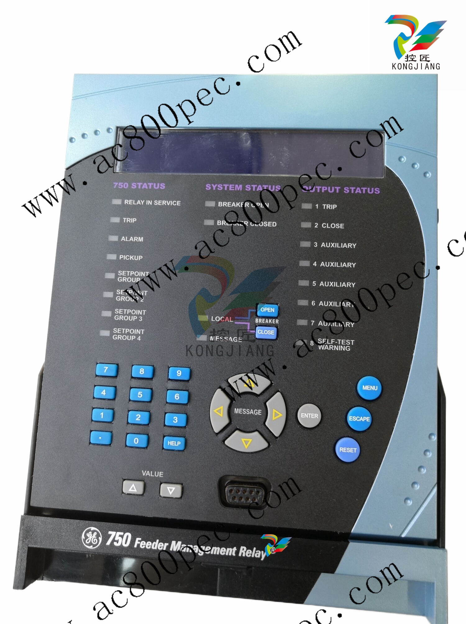
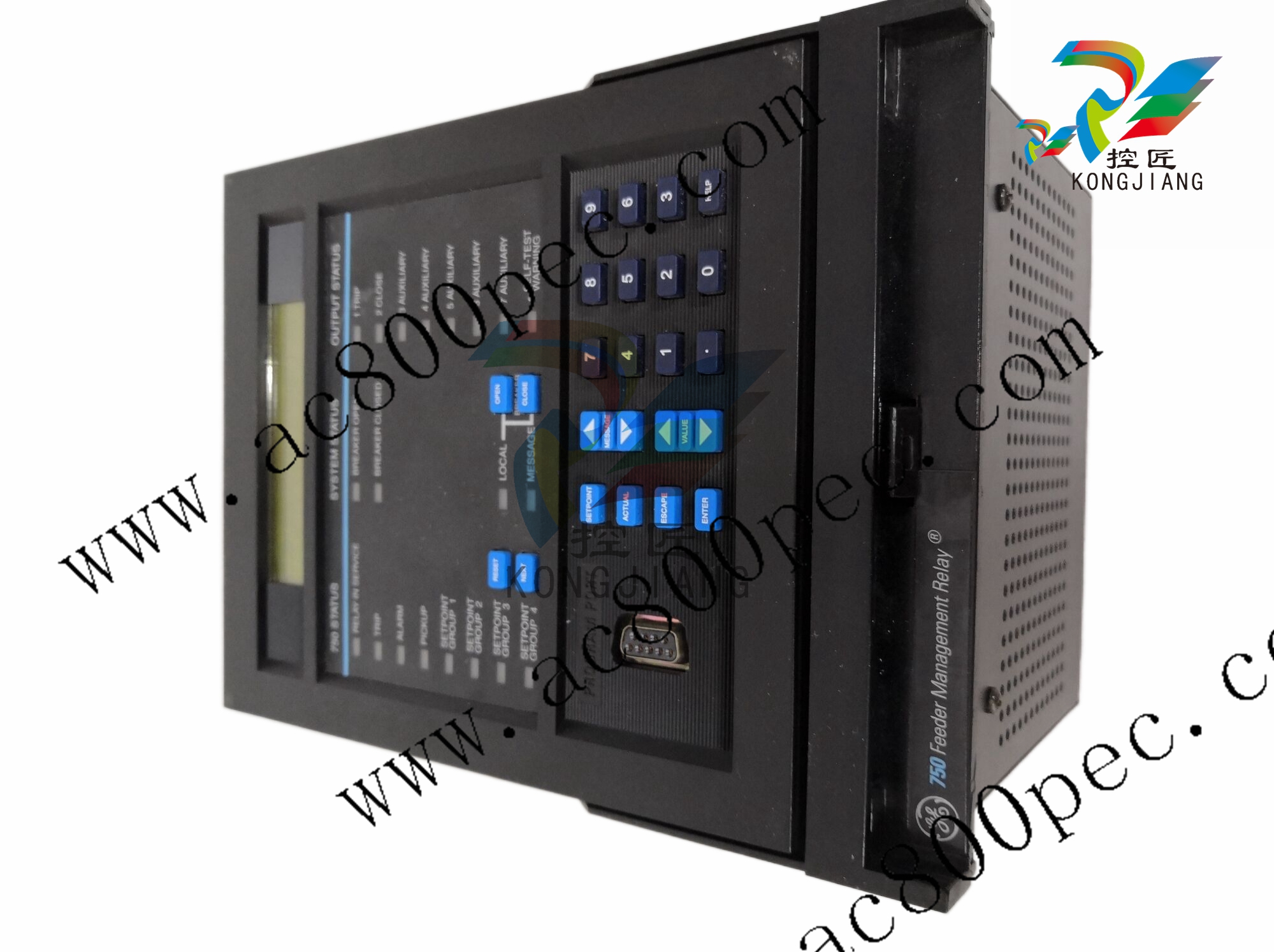
Front Panel: the enhanced 750/760 contains a larger LCD and improved menu navigation
The enhanced relay contains an improved larger LCD with 40 readily visible characters. As well, a
new menu structure and keypad functionality has been implemented to improve message navigation.
The keypad was redesigned for the improved navigation structure. A new MENU key scrolls through
setpoints, actual values and target messages, replacing the SETPOINTS, ACTUAL, and NEXT keys
on earlier versions. The MESSAGE LEFT/RIGHT keys have been introduced to navigate between
sub-menus, while the MESSAGE UP/DOWN remain to allow navigation within sub-menus. The
VALUE UP/DOWN, ENTER, ESCAPE, HELP and numerical keys remain and maintain their functionality.
The LED test feature is initiated by holding down the HELP key. The overall dimensions and mounting details for the ì-Eî option are identical to the ì-Bî option of the 750/760 relays.
Product corrections: contact information updated
The technical support e-mail address and company web site was updated to reflect the new GE Multilin website address and e-mail.
Setpoints: the default message intensity setpoint has been removed
The DEFAULT MSG INTENSITY setpoint has been removed. This feature is no longer required with
the new hardware.
Instruction manual changes
New instruction manual publication number
The enhanced 750/760 relay has been assigned publication number GEK-106471.
Updates to the instruction manual
The majority of the modifications to the instruction manual are related to the new navigation
sequence and front panel keys for browsing through setpoints, actual values, and target messages.
The content of the manual was also improved to enhance the understanding of the product.
Chapter 1 was modified for the new navigation process reflecting the additional MESSAGE keys, the
introduction of the MENU key, and the elimination of the NEXT, SETPOINT and ACTUAL keys. Additional examples were introduced to illustrate the navigation process and how to access setpoints,
actual values, and target messages. The application example was enhanced, providing additional
background and adding wiring diagrams, connection diagrams, and control schematics.
The order code, as well as the examples, was modified in chapter 2.
Chapter 3 was updated with illustrations of the new product.
In chapter 4, the drawing showing the relay faceplate was updated to reflect the new faceplate
design. The format of the diagnostic messages was changed to reflect the new presentation. The
sections that covered the PC software was replaced with a new section corresponding to the enerVista 750/760 setup software.
Chapter 5 was modified to reflect the new navigation process. All navigation instructions for setpoints were reviewed and changed accordingly. The section corresponding to the Automatic Transfer Scheme was enhanced. Due to the keypad changes, the key sequence for clearing maximum
and last demand values was changed from ìSetpoint, Decimal, Message Upî to ìMenu, Decimal,
Message Leftî.
Chapter 6 was also modified to reflect the new navigation process.
The communications chapter (Chapter 7 in the previous manual) has been removed. This information is now available as GE Publication number GEK-106473: 750/760 Communications Guide.
| User name | Member Level | Quantity | Specification | Purchase Date |
|---|


- LTI Drives
- other
- ADLINK
- Beckhoff
- Shinkawa
- Other Brands
- AMAT
- Iba
- PEPPERL+FUCHS
- Aerotech
- WATLOW
- MAN
- ADVANCED
- Abaco
- YOKOGAWA
- KOLLMORGEN
- MEGGITT
- kong-sberg
- METSO
- Motorola
- NI
- OEMAX
- RELIANCE
- scanlab
- schneider
- uniop
- Vibro-Meter
- Honeywell
- Rolls-Royce
- MOOG
- GE
- B&R
- Woodward
- Yaskawa
- xYCOM
- Siemens
- Emerson
- HIMA
- Bently
- ZYGO
- FOXBORO
- OMACO
- PROSOFT
- ENTERASYS
- TRICONEX
- Parker
- Lenze
- KEBA
- Alstom
- CTI
- ABB
- A-B

-
 SIGMATEK TAE 1941 Touch Display Unit
 -
 SIGMATEK TAE 151 Touch Display Unit
 -
 SIGMATEK AKM series servo motor
 -
 SIGMATEK S-DIAS Control System
 -
 SIGMATEK Human Machine Interface (HMI)
 -
 SIGMATEK DIAS Drive 310-23 servo amplifier
 -
 SIGMATEK CCP 521 C-DIAS processor module
 -
 MEGMEET L6 series electric drive
 -
 Sysmex XN-1000/XN-2000 Hematology Analyzer
 -
 Sysmex XN-L series (XN-530/XN-430/XN-330) fully automatic blood cell analyzer
 -
 Sysmex XN-9000 Series Fully Automated Blood Analysis Pipeline
 -
 LTI‑Motion ServoOne Field Bus Systems PROFIBUS and PROFINET
 -
 Micro Innovation MICRO PANEL GF1 Color Touch Human Computer Interface
 -
 Micro Innovation WINbloc Distributed Remote I/O System
 -
 Micro Innovation MICRO PANEL GS-2 Industrial Touch Visualization Operation Panel (HMI)
 -
 LTi LST/LSH series synchronous servo motor
 -
 LTi CDE/CDB3000 positioning controller
 -
 ENOTEC SILOTEC ® Installation and Operation Instructions for 8000 Silo Monitoring O ₂/CO ₑ Analyzer System
 -
 ENOTEC ENSITU ® 7000 Compact Oxygen Transmitter Probe
 -
 ENOTEC COMTEC ® Installation and Operation Instructions for 6000 ATEX GasEx Explosion proof O ₂/COE Analyzer System
 -
 ENOTEC Integrated Products
 -
 ENOTEC OXITEC ® 500E Extraction Oxygen Analyzer
 -
 KUKA KR CS Box-2 Compact Controller for Four Axis SCARA Robot
 -
 KUKA KR C5 slim-2 Robot Controller
 -
 KUKA KR C5 micro With KUKA System Software (KSS/VSS) Assembly Instructions
 -
 KUKA KR C5 micro controller
 -
 KUKA KR C5 Controller Assembly Instructions
 -
 KUKA KR C5 compactcab and KR C5 small-size cab cabinets
 -
 KUKA KR C4 smallsize-2 small robot control cabinet
 -
 KUKA KR C4 Midsize/KR C4 Midsize CK Assembly Manual
 -
 ENOTEC ® Installation and Operation Instructions for 5000/5000+Oxygen Analyzer System
 -
 KUKA KR C4 extended; KR C4 extended CK Assembly Instructions Assembly Manual
 -
 Assembly/Installation Manual for KUKA KR C4 Compact Control Cabinet
 -
 KUKA Sunrise Cabinet Med Medical Collaborative Robot Special Control Cabinet
 -
 KUKA Sunrise Cabinet Next Generation Small Control Cabinet
 -
 KUKA KR C4 Smallsize-2 family's smallest control cabinet
 -
 KUKA KR C4 midsize; KR C4 midsize CK medium-sized control cabinet
 -
 KUKA KR C4 extended is a high-power multi axis control cabinet
 -
 General installation and operation instructions for KUKA KR C4 and KR C4 CK controllers
 -
 KUKA KR C4 compact controller operation instructions
 -
 Installation and Operation Instructions for KUKA Robot Arm
 -
 KUKA TITAN-2 Ultra Ground Overloading Six Axis Robot
 -
 Assembly instructions for KUKA KR SCARA-2 CS series robotic arm body
 -
 KUKA MA KR SCARA X Installation Guide
 -
 KUKA KR FORTEC-2 Ultra Heavy duty Ground Six Axis Robot Mechanical Assembly Manual
 -
 KUKA KR FORTEC-2 new generation heavy-duty ground six axis robot
 -
 KUKA Robots KR 1000 titan; KR 1000 L750 titan With F Variants Assembly Instructions
 -
 KUKA KR 600 FORTEC heavy-duty six axis ground mounted industrial robot
 -
 KUKA KR 500 MT FORTEC Heavy duty Six Axis Industrial Robot
 -
 KUKA KR 360 FORTEC Heavy duty Six Axis Industrial Robot
 -
 KUKA Sunrise Cabinet Med Medical Edition Robot Controller User Manual
 -
 KUKA Robots KR SCARA HO Assembly Instructions
 -
 KUKA Robots KR QUANTEC-2 PA Assembly Instructions
 -
 KUKA Robots KR QUANTEC-2 K and KR QUANTEC-2 P With K-F and P-C Variants Assembly Instructions
 -
 KUKA Robots KR QUANTEC-2 HO Assembly Instructions
 -
 KUKA Robots KR QUANTEC-2 HC Assembly Instructions
 -
 KUKA KR QUANTEC-2 series heavy-duty ground mounted six axis industrial robot
 -
 KUKA KR QUANTEC PA series heavy-duty palletizing robot
 -
 KUKA KR IONTEC-2 series six axis industrial robot
 -
 KUKA KR IONTEC ultra series six axis heavy-duty industrial robot
 -
 KUKA KR IONTEC HO Robot Assembly Manual
 -
 KUKA Robots KR CYBERTECH-3 HW Assembly Instructions
 -
 KUKA Robots KR CYBERTECH-3 Assembly Instructions
 -
 KUKA Robots KR CYBERTECH-2 arc Assembly Instructions
 -
 KUKA Robots KR CYBERTECH nano-2 Assembly Instructions
 -
 KUKA KR CYBERTECH CR HO (KR 20 R1810-HO) assembly instructions
 -
 KUKA Robots KR CYBERTECH With F variant Assembly Instructions
 -
 KUKA KR CYBERTECH CR (KR 20 R1810-CR) Clean Room (CR) Version 6-Axis Industrial Robot
 -
 KUKA KR AGILUS-3 ultra series small six axis serial robot
 -
 KUKA KR 300 R2700-2 C-F Cast Ceiling Mounted 6-Axis Heavy duty Industrial Robot
 -
 KUKA KR 20 R1820-2 E Six Axis Industrial Robot
 -
 Assembly instructions for KUKA KR AGILUS-3 small six axis robot
 -
 KUKA KR AGILUS-2 New Generation Small Six Axis Robot
 -
 KUKA KR 1000 1300 titan PA; KR 1000 L950 titan PA With F Variants Assembly Instructions
 -
 KUKA KR 700 PA/KR 700 PA Arctic Installation Guide
 -
 KUKA KR 18 R1450-3 PP six axis ground mounted industrial robot
 -
 KUKA 12 SCARA Series 4-axis SCARA Horizontal Joint Robot
 -
 KUKA KR 4 R600 Small Six Axis Industrial Robot
 -
 Installation Guide for KUKA KR 3 R540 Small 6-Axis Industrial Robot
 -
 KUKA LBR iiwa CR Clean 7-Axis Lightweight Collaborative Robot
 -
 KUKA KR AGILUS sixx series six axis industrial robot operation instructions
 -
 KUKA 4-axis heavy-duty SCARA horizontal multi joint robot KR 60 R1200 Z400 CS
 -
 KUKA KR 23 SCARA-2 CS SCARA Horizontal Multi Joint Robot
 -
 KUKA KR 20 SCARA CS Robot Assembly Instructions
 -
 KUKA KR 15 DELTA-2 Assembly Manual
 -
 KUKA KR 13 SCARA-2 CS Assembly Manual
 -
 KUKA KR 3 D1200 (Standard Delta Robot) Assembly Instructions
 -
 KUKA KR 3 D1200 HM Assembly Manual
 -
 KUKA LBR Med 7 R800, LBR Med 14 R820 Medical Edition Robot
 -
 KUKA Robots LBR iiwa 7 R800, LBR iiwa 14 R820 Operating instructions
 -
 KUKA LBR iiwa CR (Clean Room Version Robot) Operating Instructions
 -
 Lauer PCStopline series text operation panel
 -
 KUKA LBR iisy (MA_LBR_iisy V5) assembly manual
 -
 KUKA LBR iisy 3 R760 Assembly Manual
 -
 KUKA LBR iico Collaborative Robot Assembly Manual
 -
 Lauer LCAstarline (LCA300/LCA320/LCA325) Text Display Screen
 -
 Lauer PCS950/PCS950c/PCS950e operation console
 -
 Lauer EPC Series Industrial Embedded Human Computer Integrated PC User Guide
 -
 Bonfiglioli Precision Planetary Gearbox TIR-STD ENG R07
 -
 Bonfiglioli ACT/ACU Cold Plate Inverter Installation Instructions
 -
 Bonfiglioli EM-RES-02 Expansion Module
 -
 Bonfiglioli EM-RES-01 Expansion Module
 -
 Bonfiglioli EM-IO-04 Expansion Module
 -
 Bonfiglioli EM-IO-03 Expansion Module
 -
 Bonfiglioli EM-IO-02 Expansion Module
 -
 Bonfiglioli Vectron EM-IO-01 Expansion Module
 -
 Bonfiglioli F series gearbox
 -
 Installation, operation, maintenance, and spare parts of Bonfiglioli HF series reducers
 -
 Installation, Operation, and Maintenance of Bonfiglioli 300-300M Series ATEX Reducer
 -
 Bonfiglioli R3 series planetary gearbox
 -
 Bonfiglioli C series inline helical gear explosion-proof reducer
 -
 Bonfiglioli EM-ENC-05 Expansion Module
 -
 Bonfiglioli EM-ENC-04 Expansion Module
 -
 Bonfiglioli EM-ENC-03 Expansion Module
 -
 Bonfiglioli EM-ENC-02 Expansion Module
 -
 Bonfiglioli CM-CAN CANopen communication module
 -
 Bonfiglioli EM-SYS System Bus Expansion Module
 -
 Bonfiglioli CM-PDP Profibus DP Communication Module
 -
 Bonfiglioli CM-232/CM-485/CM-485T Modbus Communication Manual
 -
 Bonfiglioli BMS series precision planetary servo reduction motor
 -
 Bonfiglioli ACTION series ACT210 (230V), ACT410 (400V) frequency converter operation manual
 -
 Bonfiglioli ACT series frequency converter
 -
 Bonfiglioli HDP/HDO series gear unit IOM installation, operation and maintenance instructions
 -
 Installation, operation, and maintenance of Bonfiglioli 300-300M series reducers
 -
 Bonfiglioli 300M Modular planetary gearboxe
 -
 Bonfiglioli 3/H series heavy-duty modular gearbox
 -
 Bonfiglioli KRG-KCG-KSD hydraulic coupling
 -
 Bonfiglioli Vectron BTD-BCR servo motor

K-JIANG

Add: Jimei North Road, Jimei District, Xiamen, Fujian, China
Tell:+86-15305925923